
 Open Access Article
 This Open Access Article is licensed under a Creative Commons Attribution-Non Commercial 3.0 Unported Licence
Anti-corrosion porous RuO2/NbC anodes for the electrochemical oxidation of phenol†
Jing Ma a,
Guotong Qin*a,
Wei Weib,
Tianliang Xiaoa,
Shaomin Liuc and
Lei Jianga
a,
Guotong Qin*a,
Wei Weib,
Tianliang Xiaoa,
Shaomin Liuc and
Lei Jianga
aKey Laboratory of Bio-Inspired Smart Interfacial Science and Technology of Ministry of Education, Beihang University, Shahe Campus, Beijing 102206, China. E-mail: qingt@buaa.edu.cn
bCollege of Biochemical Engineering, Beijing Union University, 18 Sanqu Fatouxili, Chaoyang District, Beijing 100023, China
cDepartment of Chemical Engineering, Curtin University, Perth, Western Australia 6845, Australia
First published on 3rd June 2019
Abstract
Efficient anode materials with porous structures have drawn increasing attention due to their high specific surface area, which can compensate for the slow reaction rate of electrochemical oxidation. However, the use of these materials is often limited due to their poor corrosion resistance. Herein, we report a facile scale-up method, by carbothermal reduction, for the preparation of porous niobium carbide to be used as an anode for the electrochemical oxidation of phenol in water. No niobium ions were detected when the anodes were under aggressive attack by sulfuric acid and under electrochemical corrosion tests with a current density less than 20.98 mA cm−2. The porous niobium carbide was further modified by applying a ruthenium oxide coating to improve its catalytic activity. The removal rates of phenol and chemical oxygen demand by the RuO2/NbC anode reached 1.87 × 10⁻² mg min−1 cm−2 and 6.33 × 10⁻² mg min−1 cm−2, respectively. The average current efficiency was 85.2%. Thus, an anti-corrosion, highly catalytically active and energy-efficient porous RuO2/NbC anode for the degradation of aqueous phenol in wastewater was successfully prepared.
Introduction
Electrochemical methods are frequently used to treat wastewater that contains refractory organic compounds and offer many distinct advantages, such as environmental compatibility and high efficiency.1–6 It has been determined that the electrochemical treatment of wastewater depends on a wide variety of factors, including anode materials, reaction conditions and waste characteristics.Electrochemical oxidation has been reported with different anodes, including dense and porous materials. Dense materials, such as metal electrodes,7–9 metal oxide electrodes (PbO2, Bi2O5–PbO5, IrO2 and SnO2),10,11 boron-doped diamond (BDD) electrodes12–15 and dimensionally stable anodes (DSA, i.e., Ti/IrO2, Ti/RuO2 and Ti/SnO2),16 have attracted interest from many researchers because of their improved conductivity and catalytic activity. Porous electrodes, such as active carbon fibres,17 carbon nanotubes18 and other porous materials,19–25 have been proposed as a result of their high specific surface areas, electrical conductivity and chemical resistance. The porous structures of the electrode also promote the mass transport and reaction rate in a flow-through electrolytic reactor.21 Therefore, porous anodes hold great promise in wastewater treatment. However, the main problem associated with the corrosion susceptibility of anode materials, especially the leaching of metal ions, is the risk of secondary pollution. Many researchers have coated noble metals on the surface of anodes, such as DSA materials, to increase their anti-corrosion performance. This method is not suitable for porous anodes because an excessively thick anti-corrosive layer can block the pores, and it is difficult for a thin layer to display anti-corrosion performance. Therefore, producing a self-anti-corrosion porous anode is an essential strategy to solve this problem. A homemade porous carbon membrane as the anode to remove organic pollutants by electrochemical oxidation was attempted early in our group.26 The final effluent became yellow after 12 h, and the turbidity increased slightly due to the corrosion of the carbon membrane anode. We also studied the corrosion resistance of other anode materials, such as porous titanium, titanium modified by RuO2 or Ta2O5 and substoichiometric TiO2 anodes.26–30 Although the modified anode materials exhibited superior corrosion resistance compared with that of the pristine anodes, none of these porous anodes possessed ideal corrosion resistance properties. Therefore, the development of an anti-corrosion porous anode is desired to overcome this challenge.
Transition metal carbides are well known for their extremely high hardness and high melting points. These materials are primarily used as cutting tools and thin-film coatings of microcircuit devices. Transition metal carbides also show high catalytic activities that are similar to those of noble metal catalysts, such as Pt, Pd and Ir.19 Niobium carbide (NbC) is a compound with a high melting point (>3500 °C) and high resistance to chemical attack or thermal shock, which makes it useful for high-temperature and high-stress engineering applications.31 However, there are few studies on the electrocatalytic properties of NbC.
Recently, NbC was synthesized via a few methods, including the direct reaction of Nb with carbon,32 gas–solid reactions between Nb and carbon with iodine as catalysts,33 the carbothermal reduction of metal oxides at high temperatures31 and magnetron sputtering.34 However, all of these methods are mainly used for the preparation of bulk NbC.
The aim of the present work was to develop a simple scale-up method to synthesize anti-corrosion, conductive, porous NbC anodes by carbothermal reduction of metal oxides at medium temperatures. The obtained porous NbC anodes showed excellent corrosion resistance and high electrocatalytic activity for phenol degradation. Moreover, the porous RuO2/NbC anode showed high catalytic activity and high current efficiency.
Experimental
Electrode preparation
Niobium pentaoxide nanoparticle (nano-Nb2O5) powders were synthesized using the combined citrate acid and ethylenediaminetetraacetic acid (EDTA) complexing method.35 Pre-weighted niobium oxalate was first dissolved in an EDTA–NH3·H2O solution under heating and stirring. After stirring for a certain time, citric acid was introduced, and the mole ratio of EDTA![[thin space (1/6-em)]](https://www.rsc.org/images/entities/char_2009.gif) :citric acid:total metal ions was controlled to be approximately 1:1.5:1. Since precipitation might occur after the addition of citric acid, NH3·H2O was added to adjust the pH value to ∼6, and the solution became transparent immediately. With the evaporation of water, a dark brown gel was obtained. The gel was then heated at 140 °C for 48 h to obtain a loose and porous black powder, which was further sintered at 650–1000 °C for 1 h at a heating rate of 1 °C min−1 to obtain the white Nb2O5 powder. The prepared powders mixed with a small amount of carboxymethyl cellulose were pressed into a stainless steel mould (20 mm in diameter) under a pressure of 20 MPa for 30 s. These white discs were sintered at 850 °C for 2 h in air atmosphere and then carbothermally reduced at a certain temperature for 8 h (at a heating rate of 2 °C min−1 and in a 10% methane/argon atmosphere (CH4/Ar)) to obtain the porous NbC anode.
:citric acid:total metal ions was controlled to be approximately 1:1.5:1. Since precipitation might occur after the addition of citric acid, NH3·H2O was added to adjust the pH value to ∼6, and the solution became transparent immediately. With the evaporation of water, a dark brown gel was obtained. The gel was then heated at 140 °C for 48 h to obtain a loose and porous black powder, which was further sintered at 650–1000 °C for 1 h at a heating rate of 1 °C min−1 to obtain the white Nb2O5 powder. The prepared powders mixed with a small amount of carboxymethyl cellulose were pressed into a stainless steel mould (20 mm in diameter) under a pressure of 20 MPa for 30 s. These white discs were sintered at 850 °C for 2 h in air atmosphere and then carbothermally reduced at a certain temperature for 8 h (at a heating rate of 2 °C min−1 and in a 10% methane/argon atmosphere (CH4/Ar)) to obtain the porous NbC anode.
To improve the catalytic activity, the porous NbC anode was modified with RuO2. The NbC anode was immersed in a ruthenium chloride solution (5%) in a hot reflux system for 4 h, and then the air-dried samples were heat treated at 400 °C for 2 h (under an Ar atmosphere) in a box furnace to prepare a ruthenium oxide-modified porous NbC anode. By repeating the modification process, different amounts of RuO2 were coated.
Electrochemical removal of phenol
In the undivided cell, the porous NbC anode and platinum (Pt) were used as the anode and cathode, respectively. The active dimension of the anode (4.5 cm2) was equal to that of the cathode. A saturated calomel electrode (SCE) was chosen as the reference electrode. A Luggin capillary connected the reservoir, thus connecting the reference electrode with the main electrolyte compartment. The synthetic phenol wastewater contained 200 mL phenol solution at an initial concentration of 100 mg L−1. Additionally, 0.1 M sodium sulfate (Na2SO4) was used as the electrolyte. An electrochemical workstation (CHI660E; Shanghai Chenhua Apparatus Co., China) supplied a constant current.Corrosion resistance experiments
Electrochemical corrosion resistance was evaluated in the same way as performing the electrochemical removal of phenol. For the chemical corrosion resistance test, we put the porous NbC anode in 200 mL of 50 wt% sulfuric acid (70 °C) for 9 h. The corrosion resistance of the porous materials was evaluated by the content of Nb ions in solution, which was analysed by UV-Vis spectroscopy (UV2400, Shanghai Shunyuhengping Co., China). As reported in the literature, the UV-Vis spectroscopy method is a stable, facile and reliable method for detecting Nb ions in water.36–38Analysis
The crystal structures of the nano-Nb2O5 powder and porous NbC anode were characterized by X-ray diffraction (XRD; LabX XRD-6000). The surface and cross-section morphologies of the porous NbC anode were investigated by scanning electron microscopy (SEM; Quanta FEG 250). The atomic ratio of Ru was detected by an energy spectrum analyser (EDX, INCA Energy 250). The elemental contents of the electrode surface were analysed by X-ray photoelectron spectra (XPS, Thermo Scientific Escalab 250Xi).Cyclic voltammetry (CV) experiments, electrochemical impedance spectroscopy (EIS) and potentiodynamic polarization measurements were carried out at room temperature using an electrochemical workstation with three electrodes in a 0.1 M Na2SO4 solution. The porous NbC anode (4.5 cm2) and flat Pt were used as the working electrode and counter electrode, respectively. An SCE was chosen as the reference electrode.
After each electrocatalysis process, the phenol in solution was tested by UV-Vis spectroscopy on a spectrophotometer. The chemical oxygen demand (COD) was measured using a COD reactor (HACH) and a spectrophotometer. The average current efficiency (ACE) for the anodic oxidation of phenol was calculated from the COD:
 | (1) |
485 C mol−1), V is the volume of electrolyte (L), and 8 is the equivalent mass of oxygen (g eq.−1).
Results
Characterization of the porous NbC electrode
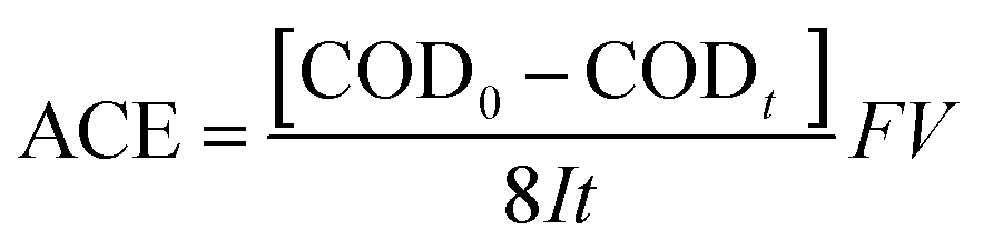
The structural and phase formation analyses of Nb2O5 and NbC at different calcination temperatures were performed by XRD. The XRD pattern resembled that of orthorhombic Nb2O5 below 800 °C according to the Joint Committee on Powder Diffraction Standards (JCPDS) number 28-0317 (Fig. 1a). Interestingly, the phase changed to monoclinic Nb2O5 after a medium temperature treatment (1000 °C). Fig. 1b shows the XRD patterns of the porous NbC anode prepared under a 10%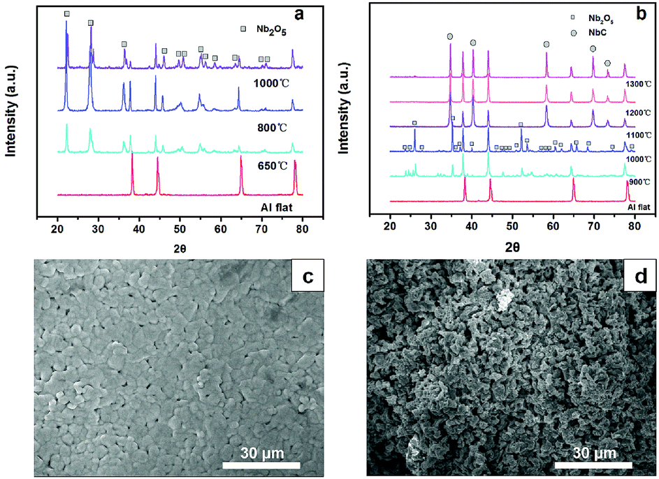 | ||
| Fig. 1 XRD patterns of Nb2O5 nanoparticles prepared under different temperatures (a) and porous flat NbC prepared under different temperatures and an atmosphere of 10% CH4/Ar (b), SEM images of the surface of porous NbC (c) and a cross-section of porous NbC (d). | ||
CH4/Ar atmosphere at different temperatures. These well-defined diffraction peaks at 35°, 40°, 58°, 69°, 73° and 75° correspond to the (111), (200), (220), (311), (222) and (400) lattice planes of NbC (JCPDS no. 89-3690), respectively, when the temperatures were higher than 1100 °C. The obtained NbC showed a well-crystallized structure. The SEM images of porous NbC are shown in Fig. 1c and d. The particles were sintered and connected to form a porous and smooth surface with a pore size of 1–2 μm, which correspond with the pore distribution results (Fig. S1†) tested by bubble-point method. The cross-section of NbC (Fig. 1d) displayed an abundance of pores resulting in a high surface area. Fig. 2a displays the C1s XPS peak of the porous NbC anode. Two deconvoluted peaks were observed in the spectrum. The strong peak centred at 284.8 eV was assigned to the carbon component in NbC (C–Nb bonds).39 The peak at 286.3 eV was identified as carbon in the amorphous matrix (C–C bonds). The XPS results indicate that there is some amorphous carbon in the obtained NbC.34 For the NbC, two apparent peaks at 207.2 eV and 204.3 eV were assigned to Nb 3d3/2 and Nb 3d5/2 of Nb, respectively (Fig. 2b).40 Therefore, we obtained porous NbC through an easy scale-up method.
 | ||
| Fig. 2 XPS spectra of NbC. C 1s (a) and Nb 3d (b). | ||
Corrosion resistance of the porous NbC electrode
We detected the concentration of Nb ions in the solution at different time intervals when we used a porous NbC anode at different current densities. For comparison, we also examined the corrosion resistances of commercial substoichiometric TiO2. The Nb ions were not detected in the solution after 9 h when the current density was lower than 20.98 mA cm−2 (Table 1). The concentration of Nb ions increased from 3.96 to 58.25 μg L−1 when the corrosion time increased from 1 h to 9 h at the applied current density of 100 mA cm−2. However, the concentration of Ti ions increased from 7.05 μg L−1 to 216.66 μg L−1 when the corrosion time increased from 1 h to 9 h at an applied current density of 20.98 mA cm−2. These results imply that the porous NbC shows better anti-corrosion capacity. To evaluate the chemical corrosion resistance, we put the porous NbC anode in a solution of 50 wt% sulfuric acid (70 °C) for 9 h, and no metal ions were detected in the solution. Therefore, the porous NbC showed promising corrosion resistance.| Electrode | Current density (mA cm−2) | Time (h) | Concentration of metal ion (μg L−1) |
|---|---|---|---|
| Porous NbC | 0 | 9 | 0 |
| 2.01 | 9 | 0 | |
| 8.77 | 9 | 0 | |
| 20.98 | 9 | 0 | |
| 100.00 | 1 | 3.96 | |
| 100.00 | 3 | 27.97 | |
| 100.00 | 5 | 31.79 | |
| 100.00 | 7 | 47.74 | |
| 100.00 | 9 | 58.25 | |
| Substoichiometric TiO2 | 20.98 | 1 | 7.05 |
| 3 | 40.51 | ||
| 5 | 75.74 | ||
| 7 | 147.97 | ||
| 9 | 216.66 |
Electrochemical removal of phenol
In Fig. 3, the cyclic voltammogram curve for the 100 mg L−1 phenol solution showed an obvious current increase at 0.4 V versus SCE. This result indicated that phenol could be electrochemically oxidized at a very low potential. No obvious peak could be seen from the CV curves because of the characteristics of carbon materials themselves.41 The porous NbC anode had an oxygen evolution potential higher than 1.5 V versus SCE when the anode current at 1.5 V was 13.93 mA cm−2 (Fig. 3), which suggested that the electrochemical catalytic performance of porous NbC was slightly higher than that of other DSAs.42 The higher oxygen evolution potential is desirable because the low probability of hydroxyl radical reactions to form molecular oxygen favours organic oxidation by hydroxyl radicals,43 and anodic oxygen evolution also represents an unwanted power loss and reduces the overall current efficiency.44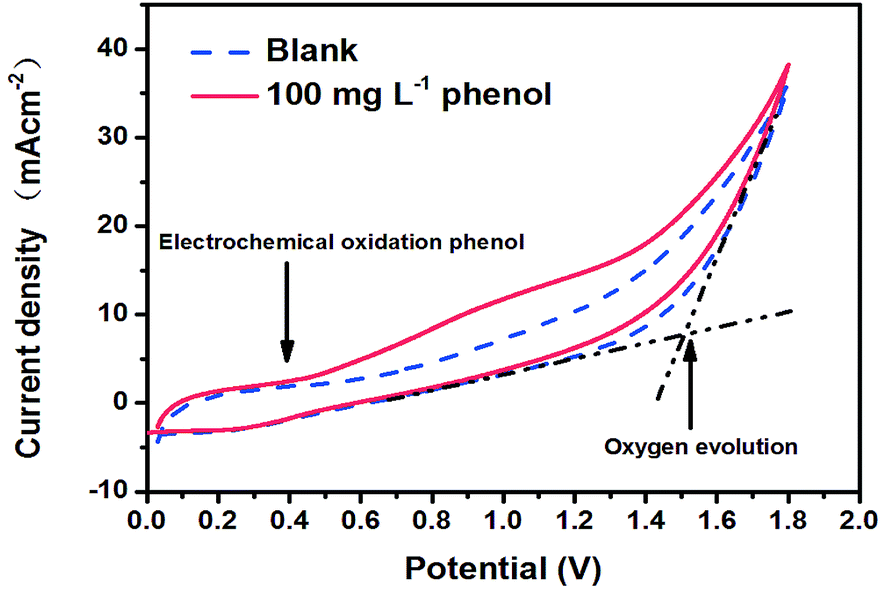 | ||
| Fig. 3 The CV curves of porous flat NbC using a 0.1 M Na2SO4 electrolyte with and without 100 mg L−1 phenol. | ||
When we used NbC as the anode, the maximum phenol, COD removal and ACE values were 82.62%, 31.08% and 51.62%, respectively, when the current density and electrode distance were 20 mA cm−2 and 4 mm with 100 mg L−1 phenols (Fig. S2†). This result indicated that the mineralization rate (31.08%) was still relatively low even if the porous NbC showed better phenol removal (82.62%).To improve the mineralization rate of NbC, RuO2 was used to modify the porous NbC. As shown in Fig. 4a and b, the phenol removal, COD removal and ACE reached maximum values of 100.00%, 71.30% and 85.22%, respectively, when the anode was modified with RuO2 three times. Compared with the values of porous NbC (Fig. S2†), the electrocatalytic activity of the modified anode (RuO2/NbC electrode) was dramatically improved (Fig. 4).
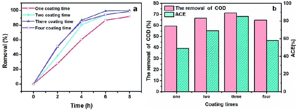 | ||
| Fig. 4 The effects of the number of RuO2 coating times on phenol removal (a), COD removal and ACE at 8 h (b) with a current density of 20 mA cm−2 and an initial phenol concentration of 100 mg L−1. | ||
Overall, we may find it difficult to evaluate the actual electrocatalytic performance of porous RuO2/NbC electrodes in this work compared with different electrodes reported in other literature because of the different reactors used. The pollutant removal rate (per unit time and electrode area) was reasonably used to evaluate the electrode electrocatalytic activity and reactor efficiency. Our main results (shown by the removal rate) compared with other literature values can be seen in Table 2. The phenol and COD removal rates by the RuO2/NbC anode were 1.87 × 10⁻² mg min−1 cm−2 and 6.33 × 10⁻² mg min−1 cm−2, respectively; these results along with the high ACE value of 85.22% mean that the porous RuO2/NbC electrode showed an excellent mineralization rate and an excellent current efficiency compared with other electrodes. These results clearly confirm that the RuO2/NbC electrode is a promising anti-corrosion anode for the electrochemical oxidation of organic pollutants in water.
| Compound | Anode materials | Concentration /electrolyte | Current density (mA cm−2) | Initial concentration (mg L−1) | Compound removal rate (mg min−1 cm−2) | COD removal rate (mg min−1 cm−2) | TOC removal rate (mg min−1 cm−2) | ICE (%) | ACE (%) | MCE (%) | Reference |
|---|---|---|---|---|---|---|---|---|---|---|---|
| a The values are calculated by the given values in the literature, and the calculation equation can be seen in the ESI. | |||||||||||
| Phenol | RuO2/NbC | 0.10 M/Na2SO4 | 19.7 | 100.00 | 1.87 × 10⁻² | 6.33 × 10⁻² | — | — | 85.2 | — | This work |
| Phenol | TiO2/RuO2/Pt | 0.05 M/NaCl | 20.0 | 8.00 | 1.60 × 10⁻³a | — | 4.08 × 10⁻³a | ∼40 | — | 25.52a | 62 |
| Phenol | Ti/SnO2–Sb2O3–Nb2O5/PbO2 | 7.50 g L−1/NaSO4 | 20.0 | 500.00 | 6.06 × 10⁻²a | 2.66 × 10⁻²a | — | ∼24.00 | 26.76a | — | 63 |
| Phenol | BDD nanowire | 0.50 M/Na2SO4 | 30.0 | 94.00 | 9.50 × 10⁻³a | 2.00 × 10⁻²a | 6.56 × 10⁻³a | ∼60.00 | 13.42a | 13.68a | 64 |
| Phenol | β-PbO2 | 1.00 g L−1/K2SO4 | 27.5 | 100.00 | 3.46 × 10⁻²a | — | — | <5.00 | — | — | 65 |
| Phenol | Ti/SnO2/Pb | 0.25 M/Na2SO4 | 20.0 | 490.00 | 2.18 × 10⁻²a | — | 5.21 × 10⁻³a | — | — | 52.09a | 43 |
| Phenol | Ti/MnOx | 0.10 M/Na2SO4 | 2.5 | 100.00 | 2.14 × 10⁻³a | — | 9.94 × 10⁻⁴a | — | — | 24.86a | 66 |
| Phenol | MnO2/Nano-G|foam-Ni/Pd | 0.10 M/Na2SO4 | 39.0 | 100.00 | 5.14 × 10⁻³a | — | 3.40 × 10⁻³a | — | — | 5.45a | 67 |
| Phenol | Nb/BDD | 0.20 M/KH2PO4 + 100 mM/NaCl | 6.46 | 50.00 | 2.69 × 10⁻²a | — | 1.23 × 10⁻³a | — | — | 11.95a | 68 |
| Tetracycline | Ti/Ti4O7 | 0.03 M/Na2SO4 | 15.0 | 5.00 | 4.69 × 10⁻⁴a | — | 2.20 × 10⁻⁴a | — | — | 9.90 | 1 |
| Tetracycline | BDD | 5.00 g L−1/Na2SO4 | 300.0 | 150.00 | 6.25 × 10⁻⁴a | 1.00 × 10⁻³a | 3.23 × 10⁻⁴a | — | 2.50a | 0.06a | 69 |
| Tetracycline | BDD | 0.05 M/Na2SO4 | 20.8 | 100.00 | 2.89 × 10⁻³a | — | 1.68 × 10⁻³a | — | — | 4.44a | 70 |
| Tetracycline | Ti/SnO2–Sb | 0.01 M/Na2SO4 | 25.0 | 5.00 | 1.13 × 10⁻³a | — | 5.69 × 10⁻⁴a | — | — | 1.25a | 71 |
| Tetracycline | porous Ti4O7 | 0.10 M/Na2SO4 | 0.5 | 10.00 | 1.57 × 10⁻⁴a | — | 3.90 × 10⁻⁵a | — | — | 4.28a | 72 |
| Tetracycline | Ti/RuO2–IrO2 | 0.10 M/Na2SO4 | 47.6 | 200.00 | 9.21 × 10⁻³a | — | — | — | — | — | 73 |
| Tetracycline | Ti/RuO2–IrO2 | 0.10 M/Na2SO4 | 565.0a | 200.00 | 2.21a | 0.60a | — | — | 21.23a | — | 74 |
| Benzoic acid | BDD | 0.05 M/Na2SO4 | 352.9a | 100.00 | 5.71 × 10⁻²a | 0.14a | — | 22.00 | 4.42a | 75 | |
| Benzoic acid | TiO2-NTs/SnO2 | 0.10 M/Na2SO4 | 14.7 | 140.00 | 9.18 × 10⁻³a | 1.44 × 10⁻²a | — | 26.40 | 19.67a | — | 76 |
| 4-Chloro-3-methyl phenol | Ti/SnO2–Sb/PbO2 | 0.25 M/Na2SO4 | 10.0 | 99.81 | 2.77 × 10⁻³a | 3.08 × 10⁻³a | 8.33 × 10⁻⁴a | 6.50 | 6.19a | — | 77 |
| 4-Chlorophenol | Er–PbO2 electrode | 0.20 M/Na2SO4 | 20.0 | 128.56 | 9.52 × 10⁻³a | 1.29 × 10⁻²a | — | 16.00 | 12.98a | — | 78 |
| 2,4-Dichlorophenol | Ti/SnO2–Sb | 0.01 M/Na2SO4 | 30.0 | 100.00 | 1.39 × 10⁻³a | — | 5.69 × 10⁻⁴a | — | — | — | 79 |
| Procion blue dye | Ti/RuOx–TiOx | — | 40.0 | — | — | 7.19 × 10⁻²a | — | — | 36.13a | — | 80 |
| Methyl orange | SnO2/TiO2-NTs/Ti | 0.10 M/Na2SO4 | 30.0 | 500.00 | 1.85 × 10⁻²a | — | 5.18 × 10⁻³a | 6.00 | — | 11.73a | 81 |
| Methyl orange | Ti/Ir–Pb | 0.05 M/Na2SO4 | 70.0 | 50.00 | 2.92 × 10⁻³a | 1.10 × 10⁻³a | — | — | 1.67 | 82 | |
| Bisphenol A | Nb/BDD | 0.10 M/Na2SO4 | 6.5 | 150.00 | — | 1.89 × 10⁻²a | — | 58.00 | 58.53a | — | 83 |
| Bisphenol A | Ti/SnO2–Sb2O5/PbO2 | 0.02 M/Na2SO4 | 40.0 | 22.83 | — | 8.78 × 10⁻³a | — | — | 4.41a | — | 84 |
| Bisphenol A | BDD | 0.04 M/NaCl | 15.0 | 13.70 | 5.71 × 10⁻²a | — | 3.51 × 10⁻³a | — | — | 33.59 | 85 |
| o-Nitrophenol | Ti/Bi–PbO2 | 0.10 M/Na2SO4 | 30.0 | 50.00 | 2.50 × 10⁻²a | 2.88 × 10⁻²a | — | — | 31.49 | — | 86 |
| o-Nitrophenol | Ti/Bi–PbO2 | 0.10 M/Na2SO4 | 30.0 | 50.00 | 2.50 × 10⁻²a | — | 3.92 × 10⁻²a | 75.60a | — | 58.29a | 87 |
| Atrazine | Ti/Ru0.3Ti0.7O2 | 0.10 M/NaCl | 50.0 | 20.00 | 5.34 × 10⁻³a | — | 1.33 × 10⁻³a | — | — | 3.12a | 88 |
| Atrazine | BDD | 0.03 M/Na2SO4 | 18.2 | 0.10 | 1.06 × 10⁻⁴a | — | 1.44 × 10⁻⁶a | — | 0.10 | 0.26a | 89 |
Discussion
Analysis of phenol removal on a porous RuO2/NbC electrode
The high electrocatalytic activity of the RuO2/NbC anode may be attributed to the interface coordination effect between the porous NbC support and the RuO2 coating. The abundant Lewis acid sites on RuO2 particles are more likely to combine hydroxyl radicals generated by electrochemical oxidation processes to form Lewis acid–base pairs,45 which can oxidize organics by direct oxidation mechanisms.46 Oxidized ruthenium ions on the surface may display a rather strong Lewis acidity.47 NbC is a well-known interstitial compound with a high density of states (DOS) at the Fermi level. This is correlated with d-band contraction caused by the expansion of the metal crystal lattice and the increase in the intermetal distance.48 The adsorbed substance (hydroxyl radicals) on the surface of NbC can influence the charge transfer dramatically.49,50 The electrodes coated by metal oxide, such as the RuO2 modified electrode, possessed various redox pairs or Lewis acid–base pairs in the potential range between the hydrogen and oxygen gas evolution regions.51,52 The NbC support may transfer electron charge to RuO2 and result in redox pair formation, which is the main factor producing hydroxyl radicals.53,54 Strong adsorption between aromatic species and transition metal oxides due to weak π bonding is a dominant factor determining electrocatalytic activity. Therefore, more phenol can be adsorbed on the RuO2.55 Additionally, the porous structure of NbC provided more surface area for the RuO2 coating, which can increase the electrocatalytic activity.Kinetic analysis of phenol removal on the porous RuO2/NbC electrode
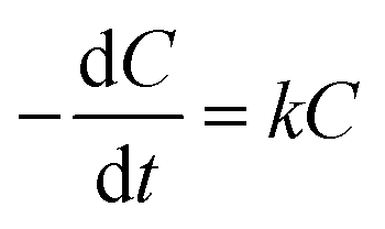
The removal of phenol on the NbC anode followed apparent pseudo-first-order kinetics according to the following rate equation:
 | (2) |
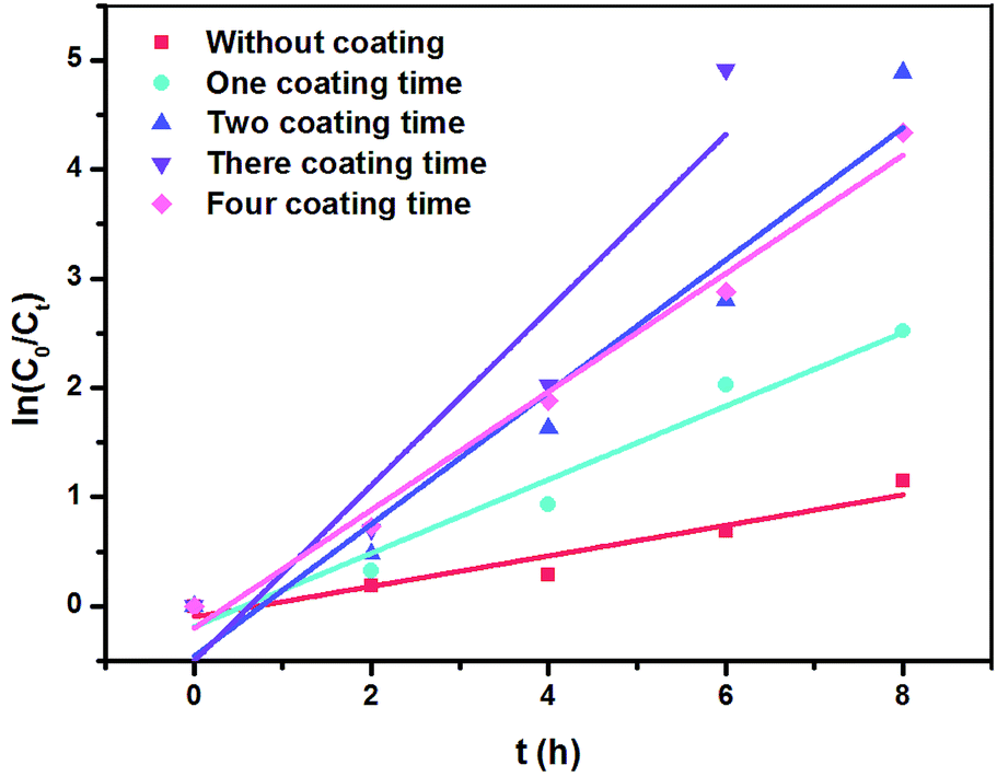 | ||
| Fig. 5 First-order kinetics for the phenol removal by RuO2/NbC and NbC anodes. | ||
| Modified times by RuO2 | Phenol removal (%) | COD removal (%) | ACE (%) | Reaction rate constant (h−1) | Half-life (t1/2, h) | R2 |
|---|---|---|---|---|---|---|
| 0 | 68.22 | 20.64 | 34.29 | 0.14 | 5.67 | 0.91 |
| 1 | 91.96 | 59.50 | 49.00 | 0.34 | 2.60 | 0.96 |
| 2 | 99.25 | 66.74 | 69.14 | 0.60 | 1.76 | 0.93 |
| 3 | 100.00 | 71.30 | 85.22 | 0.80 | 1.49 | 0.87 |
| 4 | 98.69 | 64.90 | 57.87 | 0.54 | 1.65 | 0.98 |
These results were consistent with the changes in phenol removal (from 68.22% to 100%), COD removal (from 20.64% to 71.30%) and ACE (from 34.29% to 85.22%), which implies that the RuO2/NbC anode shows a higher mineralization rate and current efficiency. It is worth mentioning that the k value showed little change when the coating was modified four times, implying that a thicker RuO2 layer may block the holes in porous NbC and decrease the surface area. This result was possibly attributed to the limited number of catalytically active sites in the porous RuO2/NbC anode.
The corrosion resistance of the porous NbC electrode
The corrosion resistance of porous anodes is always low, which limits the application of anodes for industrial wastewater treatment. According to some studies,57–59 the most frequently used method to solve the above-mentioned problem is slurry coating sintering, which is suitable for dense materials except for porous materials. However, this method may block the pores and reduce the surface area, which would limit the reactor efficiency. Therefore, the development of an anti-corrosion support is a promising strategy. We present an anti-corrosion porous NbC anode with higher electrocatalytic properties than those of other anodes. To understand the anti-corrosion properties of the NbC electrode, an EIS experiment was conducted. The impedance spectra for the NbC anode and RuO2/NbC anode in 0.1 M Na2SO4 solution are presented as Nyquist plots in Fig. 6. The Nyquist plots (Fig. 6a) showed a single depressed semicircle, and the diameter of the semicircle increased after modifying NbC with RuO2. The results indicated that the RuO2 coating can slightly improve the corrosion protective properties, in which the RuO2/NbC electrode showed the best performance.60 The Bode plots shown in Fig. 6b and c also help explain these results. Potentiodynamic polarization measurements were carried out immediately after the EIS experiments. Fig. 6d shows the polarization curves of the RuO2/NbC and NbC anodes in 0.1 M Na2SO4 solution. The electrochemical parameters can be summarized in Table 4, including the corrosion current density (Icorr), corrosion potential (Ecorr), anodic Tafel slopes (βa) and cathodic Tafel slopes (βc). Overall, a lower Icorr and a higher Ecorr mean better corrosion protective properties.61 The Icorr of the RuO2/NbC anode was 4.07 μA cm−2, which was lower than that of the bare NbC anode (25.40 μA cm−2). Moreover, the Ecorr of the RuO2/NbC anode (−0.74 V) was more positive than that of the bare NbC (−0.81 V). These results mean that the RuO2/NbC anode displayed superior anti-corrosion properties compared with the bare NbC anode. According to the values shown in Table 1, the porous NbC electrode presented better anti-corrosion properties than those of substoichiometric TiO2. Therefore, the porous RuO2/NbC anode combines superior corrosion resistance and high electrocatalytic activity, making it a preferred anode material for the electrochemical oxidation of pollutants.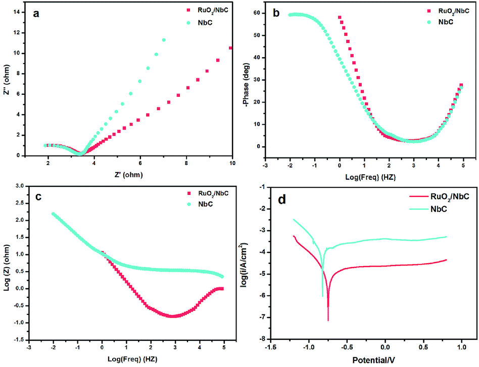 | ||
| Fig. 6 Nyquist plots (a), Bode plots (b, c), and Tafel plots (d) of the NbC substrate and RuO2/NbC in 0.1 M Na2SO4. | ||
| Sample | Ecorr (V) | Icorr (μA cm−2) | βc (mV dec−1) | βa (mV dec−1) |
|---|---|---|---|---|
| NbC | −0.81 | 25.40 | 17.00 | −10.00 |
| RuO2/NbC | −0.74 | 4.07 | 2.74 | −6.13 |
Conclusions
We developed a simple scale-up method for the preparation of anti-corrosion porous NbC anodes by the carbothermal reduction of porous Nb2O5. The resultant porous anodes showed good performance in various corrosion tests. By modifying RuO2, the porous RuO2/NbC anode exhibited high electrocatalytic activity and high current efficiency in the electrochemical oxidation of phenol. The achieved phenol and COD removal rates were 1.87 × 10⁻² mg min−1 cm−2 and 6.33 × 10⁻² mg min−1 cm−2, respectively, with the ACE value reaching 85.22%. These promising results pave a way to develop porous anodes for the electrochemical oxidation of organic waste.Conflicts of interest
There are no conflicts to declare.Acknowledgements
This work was supported by the National Natural Science Foundation of China (Grant No. 51678019).References
- S. D. Jojoa-Sierra, J. Silva-Agredo, E. Herrera-Calderon and R. A. Torres-Palma, Sci. Total Environ., 2017, 575, 1228–1238 CrossRef CAS PubMed.
- C. Sola-Gutierrez, M. F. San Roman and I. Ortiz, Sci. Total Environ., 2018, 626, 126–133 CrossRef CAS PubMed.
- H. Song, L. Yan, J. Ma, J. Jiang, G. Cai, W. Zhang, Z. Zhang, J. Zhang and T. Yang, Water Res., 2017, 116, 182–193 CrossRef CAS PubMed.
- C. Trellu, C. Coetsier, J. C. Rouch, R. Esmilaire, M. Rivallin, M. Cretin and C. Causserand, Water Res., 2017, 131, 310–319 CrossRef PubMed.
- J. Wang, D. Zhi, H. Zhou, X. He and D. Zhang, Water Res., 2018, 137, 324–334 CrossRef CAS PubMed.
- M. Zaghdoudi, F. Fourcade, I. Soutrel, D. Floner, A. Amrane, H. Maghraoui-Meherzi and F. Geneste, J. Hazard. Mater., 2017, 335, 10–17 CrossRef CAS PubMed.
- G. E. Dima, A. C. A. de Vooys and M. T. M. Koper, J. Electroanal. Chem., 2003, 554–555, 15–23 CrossRef CAS.
- I. Katsounaros, M. Dortsiou and G. Kyriacou, J. Hazard. Mater., 2009, 171, 323–327 CrossRef CAS PubMed.
- D. Reyter, D. Bélanger and L. Roué, Electrochim. Acta, 2008, 53, 5977–5984 CrossRef CAS.
- P. J. Kulesza, I. S. Pieta, I. A. Rutkowska, A. Wadas, D. Marks, K. Klak, L. Stobinski and J. A. Cox, Electrochim. Acta, 2013, 110, 474–483 CrossRef CAS PubMed.
- S. Zhu, B. Dong and S. Zhou, Clean: Soil, Air, Water, 2018, 46, 1700077 Search PubMed.
- P. Canizares, J. Lobato, R. Paz, M. A. Rodrigo and C. Saez, Water Res., 2005, 39, 2687–2703 CrossRef CAS PubMed.
- J. Iniesta, P. A. Michaud, M. Panizza, G. Cerisola, A. Aldaz and C. Comninellis, Electrochim. Acta, 2001, 46, 3573–3578 CrossRef CAS.
- H. Jalife-Jacobo, R. Feria-Reyes, O. Serrano-Torres, S. Gutiérrez-Granados and J. M. Peralta-Hernández, J. Hazard. Mater., 2016, 319, 78–83 CrossRef CAS PubMed.
- Y. Qi, H. Long, L. Ma, Q. Wei, S. Li, Z. Yu, J. Hu, P. Liu, Y. Wang and L. Meng, Appl. Surf. Sci., 2016, 390, 882–889 CrossRef CAS.
- L. S. Andrade, R. C. Rocha-Filho, N. Bocchi, S. R. Biaggio, J. Iniesta, V. García-Garcia and V. Montiel, J. Hazard. Mater., 2008, 153, 252–260 CrossRef CAS PubMed.
- K. Xu, X. Fu, H. Li and Z. Peng, Appl. Surf. Sci., 2018, 456, 230–237 CrossRef CAS.
- J. Yang, J. Wang and J. Jia, Environ. Sci. Technol., 2009, 43, 3796–3802 CrossRef CAS PubMed.
- M. Käärik, M. Arulepp, M. Kook, U. Mäeorg, J. Kozlova, V. Sammelselg, A. Perkson and J. Leis, J. Porous Mater., 2017, 25, 1057–1070 CrossRef.
- P. Liu, J. Keller and W. Gernjak, Sci. Total Environ., 2016, 550, 95–102 CrossRef CAS PubMed.
- R. Menini, Y. M. Henuset and J. Fournier, J. Appl. Electrochem., 2005, 35, 625–631 CrossRef CAS.
- S. Nayak and B. P. Chaplin, Electrochim. Acta, 2018, 263, 299–310 CrossRef CAS.
- L. A. Rodrigues, L. A. de Sousa Ribeiro, G. P. Thim, R. R. Ferreira, M. O. Alvarez-Mendez and A. d. R. Coutinho, J. Porous Mater., 2012, 20, 619–627 CrossRef.
- S. You, B. Liu, Y. Gao, Y. Wang, C. Y. Tang, Y. Huang and N. Ren, Electrochim. Acta, 2016, 214, 326–335 CrossRef CAS.
- Z. Zhou, A. Chen, X. Fan, A. Kong and Y. Shan, Appl. Surf. Sci., 2019, 464, 380–387 CrossRef CAS.
- L. Huang, Treatment of light polluted water with electro-catalytic membrane reactor, Beihang, Beijing, China, 2007 Search PubMed.
- P. Duan, Preparation and Properties of Corrosion-resistant Electro-catalytic Membrane Electrode, Beihang Beijing, China, 2012 Search PubMed.
- X. Li, Treatment of artificial wastewater with electro-catalytic membrane reactor, Beihang University, Beijing, China, 2008 Search PubMed.
- J. Wang, Study on Electro-catalytic Treatment of Model Phenol-containing Wastewater with Modified Ti Membrane, Beihang, Beijing, China, 2011 Search PubMed.
- X. Zhong, Preparation, modification and electro-catalytic activity of phenolic resin-based carbon membrane for removing phenol, Beihang, Beijing, China, 2009 Search PubMed.
- S. Shimada, T. Koyama, K. Kodaira and T. Mastushita, J. Mater. Sci., 1983, 18, 1291–1296 CrossRef CAS.
- S. Meyer, A. V. Nikiforov, I. M. Petrushina, K. Köhler, E. Christensen, J. O. Jensen and N. J. Bjerrum, Int. J. Hydrogen Energy, 2015, 40, 2905–2911 CrossRef CAS.
- K. Chen, X. Huang, Z. Zhang, A. Du, B. Zhou, Y. Xu, Z. Zhou and Y. Wang, J. Mater. Chem. A, 2015, 3, 11745–11749 RSC.
- N. Nedfors, O. Tengstrand, E. Lewin, A. Furlan, P. Eklund, L. Hultman and U. Jansson, Surf. Coat. Technol., 2011, 206, 354–359 CrossRef CAS.
- Z. Shao, W. Yang, Y. Cong, H. Dong, J. Tong and G. J. Xiong, Membrane. Sci., 2000, 172, 177–188 CrossRef CAS.
- G. J. P. Deblonde, A. Moncomble, G. Cote, S. Bélair and A. Chagnes, RSC Adv., 2015, 5, 7619–7627 RSC.
- S. Inoue, O. Mishima, Q. Zhang, H. Minami and M. Uto, Anal. Lett., 2001, 34, 2465–2475 CrossRef CAS.
- K. D. Nagiev, J. Anal. Chem., 2004, 59, 930–934 CrossRef CAS.
- Y. Liu, S. Shen, J. Zhang, W. Zhong and X. Huang, Appl. Surf. Sci., 2019, 478, 762–769 CrossRef CAS.
- C. F. Miller, G. W. Simmons and R. P. Wei, Scr. Mater., 2000, 42, 227–232 CrossRef CAS.
- J. W. Peel, K. J. Reddy, B. P. Sullivan and J. M. Bowen, Water Res., 2003, 37, 2512–2519 CrossRef CAS PubMed.
- Y. J. Feng and X. Y. Li, Water Res., 2003, 37, 2399–2407 CrossRef CAS PubMed.
- X. Y. Li, Y. H. Cui, Y. J. Feng, Z. M. Xie and J. D. Gu, Water Res., 2005, 39, 1972–1981 CrossRef CAS PubMed.
- S. Stucki, R. Kötz, B. Carcer and W. Suter, J. Appl. Electrochem., 1991, 21, 99–104 CrossRef CAS.
- Z. Liu, H. Li, M. Li, C. Li, L. Qian, L. Su and B. Yang, Electrochim. Acta, 2018, 290, 109–117 CrossRef CAS.
- P. Kaur, J. P. Kushwaha and V. K. Sangal, Process Saf. Environ. Prot., 2017, 111, 13–22 CrossRef CAS.
- M. Sorlino and G. Busca, Appl. Surf. Sci., 1984, 18, 268–272 CrossRef CAS.
- S. T. Oyama, Catal. Today, 1992, 15, 179–200 CrossRef CAS.
- S. A. Jansen and R. Hoffmann, Surf. Sci., 1988, 197, 474–508 CrossRef CAS.
- L. I. Johansson, Surf. Sci. Rep., 1995, 21, 177–250 CrossRef CAS.
- J. O. M. Bockris, Colloids Surf., 1983, 7, 161–162 CrossRef.
- S. Trasatti, Electrodes of Conductive Metallic Oxides, Part B, Elsevier, Amsterdam, 1981 Search PubMed.
- N. S. Ramgir, I. S. Mulla and K. P. Vijayamohanan, Sens. Actuators, B, 2005, 107, 708–715 CrossRef CAS.
- W. Zhong, W. Tu, S. Feng and A. Xu, J. Alloys Compd., 2019, 772, 669–674 CrossRef CAS.
- S. M. Lin and T. C. Wen, J. Appl. Electrochem., 1995, 25, 73–79 CrossRef CAS.
- W. Zhong, S. Shen, S. Feng, Z. Lin, Z. Wang and B. Fang, CrystEngComm, 2018, 20, 7851–7856 RSC.
- V. Panić, A. Dekanski, S. K. Milonjić, R. Atanasoski and B. Nikolić, Mater. Sci. Forum, 2000, 352, 117–122 Search PubMed.
- V. Panić, A. Dekanski, V. B. Mišković-Stanković, S. Milonjić and B. Nikolić, J. Electroanal. Chem., 2005, 579, 67–76 CrossRef.
- V. V. Panić, V. M. Jovanović, S. I. Terzić, M. W. Barsoum, V. D. Jović and A. B. Dekanski, Surf. Coat. Technol., 2007, 202, 319–324 CrossRef.
- Z. Liu, M. Zhu, L. Zhao, C. Deng, J. Ma, Z. Wang, H. Liu and H. Wang, Chem. Eng. J., 2017, 314, 59–68 CrossRef.
- H. Lu, S. Zhang, W. Li, Y. Cui and T. Yang, ACS Appl. Mater. Interfaces, 2017, 9, 4034–4043 CrossRef CAS PubMed.
- M. Li, C. Feng, W. Hu, Z. Zhang and N. Sugiura, J. Hazard. Mater., 2009, 162, 455–462 CrossRef CAS PubMed.
- X. Yang, R. Zou, F. Huo, D. Cai and D. Xiao, J. Hazard. Mater., 2009, 164, 367–373 CrossRef CAS PubMed.
- C.-H. Lee, E.-S. Lee, Y.-K. Lim, K.-H. Park, H.-D. Park and D.-S. Lim, RSC Adv., 2017, 7, 6229–6235 RSC.
- Z. Wu and M. Zhou, Environ. Sci. Technol., 2001, 35, 2698–2703 CrossRef CAS.
- A. Massa, S. Hernández, S. Ansaloni, M. Castellino, N. Russo and D. Fino, Electrochim. Acta, 2018, 273, 53–62 CrossRef CAS.
- D. Li, T. Sun, L. Wang and N. Wang, Electrochim. Acta, 2018, 282, 416–426 CrossRef CAS.
- J. Wang, D. Zhi, H. Zhou, X. He and D. Zhang, Water Res., 2018, 137, 324–334 CrossRef CAS PubMed.
- C. I. Brinzila, M. J. Pacheco, L. Ciríaco, R. C. Ciobanu and A. Lopes, Chem. Eng. J., 2012, 209, 54–61 CrossRef CAS.
- N. Oturan, J. Wu, H. Zhang, V. K. Sharma and M. A. Oturan, Appl. Catal., B, 2013, 140–141, 92–97 CrossRef CAS.
- D. Zhi, J. Qin, H. Zhou, J. Wang and S. Yang, J. Appl. Electrochem., 2017, 47, 1313–1322 CrossRef CAS.
- S. Liang, H. Lin, X. Yan and Q. Huang, Chem. Eng. J., 2018, 332, 628–636 CrossRef CAS.
- H. Zhang, F. Liu, X. Wu, J. Zhang and D. Zhang, Asia-Pac. J. Chem. Eng., 2009, 4, 568–573 CrossRef CAS.
- J. Wu, H. Zhang, N. Oturan, Y. Wang, L. Chen and M. A. Oturan, Chemosphere, 2012, 87, 614–620 CrossRef CAS PubMed.
- T. Velegraki, G. Balayiannis, E. Diamadopoulos, A. Katsaounis and D. Mantzavinos, Chem. Eng. J., 2010, 160, 538–548 CrossRef CAS.
- P. Li, G. Zhao, X. Cui, Y. Zhang and Y. Tang, J. Phys. Chem. C, 2009, 113, 2375–2383 CrossRef CAS.
- S. Song, L. Zhan, Z. He, L. Lin, J. Tu, Z. Zhang, J. Chen and L. Xu, J. Hazard. Mater., 2010, 175, 614–621 CrossRef CAS PubMed.
- J. Kong, S. Shi, L. Kong, X. Zhu and J. Ni, Electrochim. Acta, 2007, 53, 2048–2054 CrossRef CAS.
- J. Niu, D. Maharana, J. Xu, Z. Chai and Y. Bao, J. Environ. Sci., 2013, 25, 1424–1430 CrossRef CAS.
- C. A. Basha, J. Sendhil, K. V. Selvakumar, P. K. A. Muniswaran and C. W. Lee, Desalination, 2012, 285, 188–197 CrossRef CAS.
- K. Zhao, G. Zhao, P. Li, J. Gao, B. Lv and D. Li, Chemosphere, 2010, 80, 410–415 CrossRef CAS.
- E. Isarain-Chávez, M. D. Baró, E. Rossinyol, U. Morales-Ortiz, J. Sort, E. Brillas and E. Pellicer, Electrochim. Acta, 2017, 244, 199–208 CrossRef.
- G. F. Pereira, R. C. Rocha-Filho, N. Bocchi and S. R. Biaggio, Chem. Eng. J., 2012, 198–199, 282–288 CrossRef CAS.
- B. Xue, Y. Zhang and J. Y. Wang, Procedia Environ. Sci., 2011, 10, 647–652 CrossRef CAS.
- H. Li, Y. Long, X. Zhu, Y. Tian and J. Ye, Electrochim. Acta, 2017, 246, 1121–1130 CrossRef CAS.
- Y. Liu and H. Liu, Electrochim. Acta, 2008, 53, 5077–5083 CrossRef CAS.
- H. Liu, Y. Liu, C. Zhang and R. J. Shen, Appl. Electrochem., 2007, 38, 101–108 CrossRef.
- G. R. Malpass, G. R. Salazar-Banda, D. W. Miwa, S. A. Machado and A. Motheo, J. Environ. Technol., 2013, 34, 1043–1051 CrossRef CAS PubMed.
- S. Komtchou, A. Dirany, P. Drogui, D. Robert and P. Lafrance, Water Res., 2017, 125, 91–103 CrossRef CAS PubMed.
Footnote |
| † Electronic supplementary information (ESI) available. See DOI: 10.1039/c9ra03353j |
| This journal is © The Royal Society of Chemistry 2019 |