DOI:
10.1039/C9RA03315G
(Paper)
RSC Adv., 2019,
9, 22032-22044
The evaluation of a methane autothermal chemical looping reforming experiment based on exergy analysis
Received
4th May 2019
, Accepted 1st July 2019
First published on 16th July 2019
Abstract
Compared with a double circulation fluidized bed, an internally circulating reactor (ICR) has a wider pressure range, thereby increasing the conversion efficiency of methane and reducing the cost. However, since the ICR is a new reactor, there is a lack of detailed analysis and research on the internal processes inside the reactor. Consequently, in this paper, a detailed exergy analysis and an advanced exergetic analysis are utilized to evaluate a methane autothermal chemical looping reforming experiment carried out on an ICR. A detailed analysis of the internal exergy destruction of the ICR is carried out by establishing a mathematical model for the enthalpy and exergy of the substance. The exergy destruction inside reactors is divided into the exergy destruction in the chemical reaction process, the destruction of thermal exergy and other flowing exergy destruction. The influences of the CH4/NiO molar ratio and addition of steam or not on exergy destruction are studied. With the increase of CH4/NiO molar ratio, the chemical looping reforming process gradually supersedes the chemical looping combustion process and becomes the dominating reaction, which exerts a strong beneficial influence on the reduction of exergy destruction of chemical reactions. When the CH4/NiO molar ratio is 0.60, the exergy efficiency of the product is up to 52.17%. The advanced exergetic analysis provides a direction for improving the experiment. Based on these results, the ICR is evaluated in all aspects, including comparative evaluation, existing limitations, and possible future work.
1 Introduction
Syngas with CO and H2 as the main components is one of the most important chemical materials and can be used to produce methanol, gasoline and other chemical products. The syngas production unit takes up most of the equipment cost and production cost in the production process of the above products.1,2 Therefore, it is of great significance to optimize the production process of syngas. Syngas is often chemically produced from coal, petroleum fractions, natural gas, biomass, and other hydrocarbons. Among them, the production of syngas from natural gas is mature and has a good effect and a low cost, thus becoming the fastest-growing and most-studied technical direction.3 Traditional ways to produce syngas from natural gas include steam methane reforming (SMR), partial oxidation, and carbon dioxide reforming. In general, these methods have the defects of high energy consumption, large carbon dioxide emission and serious carbon deposition in the reactor.4,5
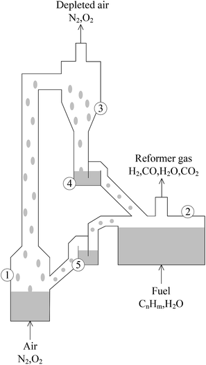
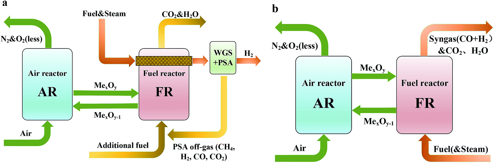
As a fast-growing technology, chemical looping reforming (CLR) has outstanding advantages and dispenses with an air separation plant and a capture device which is used to treat CO2 in the tail gas. It is the most promising process in the future energy utilization.6,7 Chemical looping reforming technology is divided into chemical looping steam methane reforming (CL-SMR) and autothermal chemical looping reforming (a-CLR). CL-SMR was first presented by Rydén et al.8 The schematic diagram is shown in Fig. 1(a). CL-SMR is a combination of two units, that is, chemical looping combustion (CLC) and SMR. In the CLC unit, the fuel reactor (FR) surrounds the reforming reactor, and the CLC unit offers the heat required by reforming reaction. Special attention should be paid to the fact that the heat required by the reforming reaction is offered by the sensible heat that the high-temperature oxygen carrier (OC) carries from the air reactor (AR) to FR. In chemical looping technology, the OC is not only a supplier of oxygen but also a heat transfer medium and a catalyst (used to catalyze the reforming reaction of CLR). Through water-gas shift reaction and pressure swing adsorption, the syngas generated in the reforming reaction further produces hydrogen with high purity. After treatment, the tail gas can return to the combustion reactor, as fuel for CLC. The a-CLR is highly similar to the CLC. It was first presented by Mattisson and Lyngfelt.9 The schematic diagram is shown in Fig. 1(b). Different from CLC which aims at obtaining efficient thermal energy, a-CLR uses a low OC circulation rate to make the fuel oxidized incompletely under insufficient oxygen supply, thereby producing syngas. Sometimes, in order to improve the hydrogen-carbon ratio of the product, a certain amount of steam may be added when fuel is fed. The reduced OC is oxidized and regenerated in AR and prepared for the next circulation. Through the regulation of the feed ratio of fuel, steam, and air, the whole unit can stay in an autothermal process without the need for an external heat source.10 At the same time, it has the advantages of capturing CO2 and generating syngas with a H2/CO molar ratio of 2. This ratio is suitable for Fischer–Tropsch synthesis or methanol synthesis.11,12 At present, the research interests of CLR mainly include the selection of an efficient and economic wear-resistant OC, the design of a unit with high energy efficiency and the development of a reactor adapting to high temperature and high pressure, with excellent mass and heat transfer capacity and airtightness.13–15
 |
| | Fig. 1 Schematic diagram of (a) the chemical looping-steam methane reforming and (b) the auto-thermal chemical looping-steam methane reforming. | |
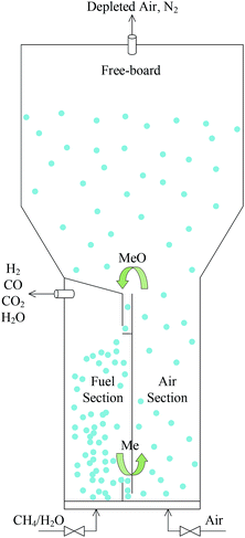
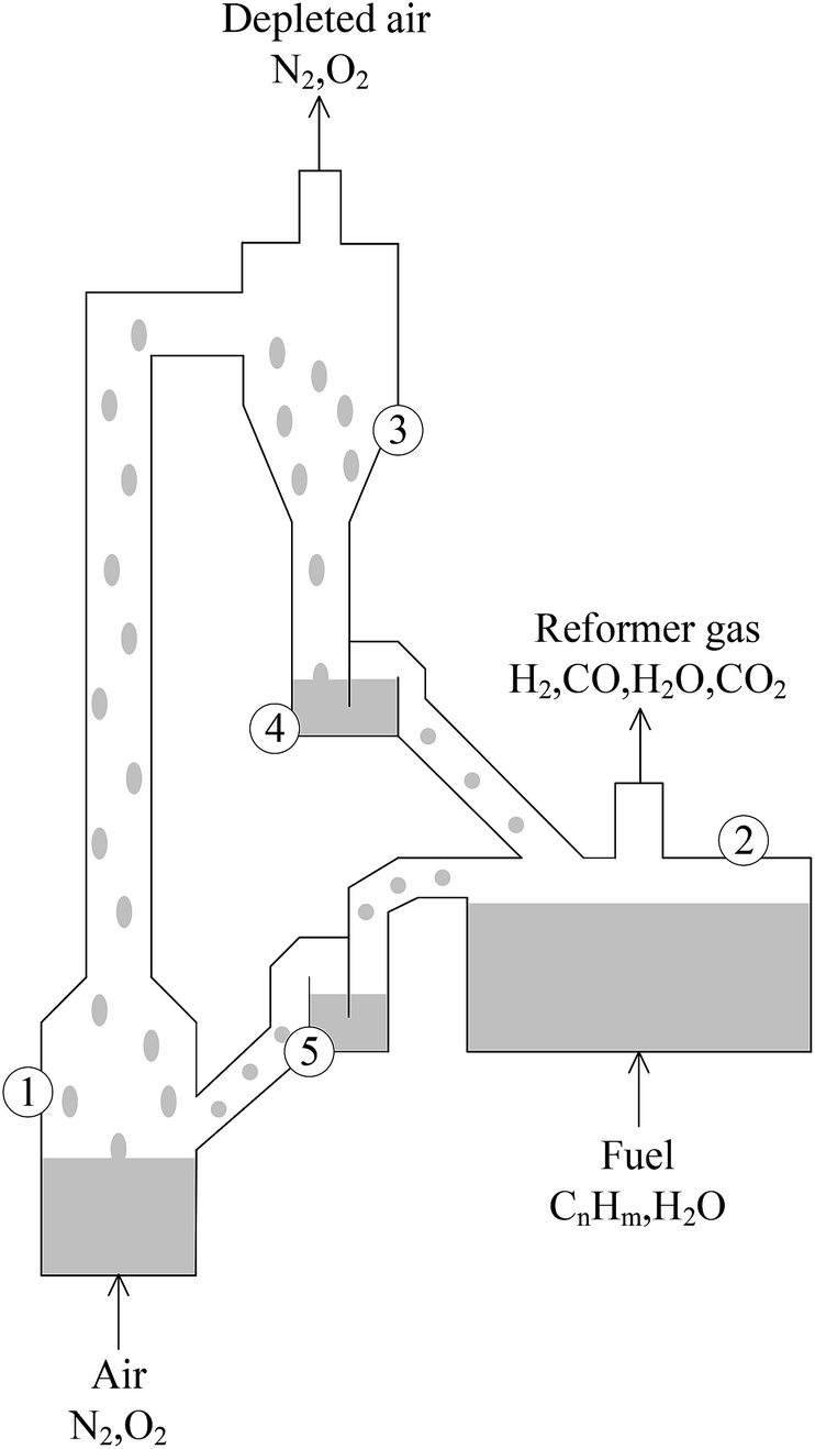
The circulating fluidized bed reactor (CFBR), applicable to CLC and CLR processes with coal and natural gas as raw materials, is the most-studied reactor type.16–18 It was first presented by Lyngfelt et al. and composed of a FR, an AR, a cyclone separator, a riser and looping seals, as shown in Fig. 2.9 According to relevant studies, pressurization has a lot of benefits to the CLR process, such as improving the conversion rate of carbon, increasing the combustion efficiency, improving the purity of CO2 captured and reducing the total capital cost of hydrogen production.19–21 However, the CFBR has obvious disadvantages in pressurization. This is because with the increase of pressure, the efficiency of cyclone separator would decrease, while and the destruction of OC particles would increase.22,23 Under pressurization, the circulation effect of solids in the looping seals is also a big problem.24
 |
| | Fig. 2 Schematic diagram of the circulating fluidized bed. (1) Air reactor, (2) fuel reactor, (3) cyclone for particle separation, (4) and (5) loop seals fluidized with steam. | |
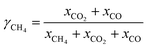
Therefore, the proposal of an internally circulating reactor (ICR) offers a new approach to achieve the pressurization of CLR, as shown in Fig. 3. The difference between this reactor and CFBR was that it replaces the looping seal in the traditional structure with simple ports and replaces the cyclone separator at the top with a freeboard. And the ICR was divided into AR and FR with a vertical partition. An L-type connecting port is designed at the top and bottom respectively, to act as a circulation channel of the OC. The enlarged freeboard zone at the top of AR acted as a “speed bump” of the OC, avoided the elution of particles and made the OC fall into the upper port at a reduced speed, so that they can be circulated to FR. The circulation of solids was still achieved by feeding them into the reactor using gases at different speeds. The gas flow rate in AR was faster than that in FR.
 |
| | Fig. 3 Simplified scheme of the ICR design. | |
A bubbling fluidized system and a fast fluidized system in AR and FR were set up respectively, by regulating the gas flow rate in each reactor. The solid particles in FR gathered at the bottom port, thus creating a pressure difference on both sides of the port and offering a drive for solids to circulate back to AR. The particles at the port formed a physical plug and thus minimized the gas leakage. To simplify the design of the inlet of ICR, the gas inflow into each reactor was realized through a cylindrical tube at the bottom. An electric heater was set at the bottom of the reactor, to preheat the reactor and regulate the autothermal process of the reaction. The reactor was put into a cylindrical shell. At the same time, to avoid large heat losses, insulating material (glass wool) needed to be placed around the reactor.
With a simple design, the ICR integrated the functions of AR, FR, cyclone separator and looping seal and simplified the operating process of these devices. The cyclone separator, the looping seal and the riser for solids transport were replaced with short and simple ports, so that the ICR can effectively control the high solids circulation rate even at a high pressure. Moreover, since the internal pressure was almost constant, the ICR didn't require a separate pressure shell for each component as the CFBR did, thereby reducing the cost of pressure equipment. Currently, the research for ICR is mainly focused on hydrodynamics and the establishment of reactive multiphase flow models.25,26 However, the detailed thermodynamic evaluation of the CLR process in ICR has not been involved.
Exergy refers to the maximum useful work possible during a process that brings a system or substance into equilibrium with the environment. The exergy analysis provides a measure for assessing the “quality” of energy. In previous studies, the way researchers used exergy analysis was to treat a reactor or unit as a black box and ignored the detailed process of internal exergy destruction, that is, the exergy of the input minus the exergy of the output.27,28
In the present study, the ICR concept designed by Osman et al. and their experiment data are used.29 By establishing a mathematical model for the process inside ICR and the thermodynamic data of substance, a thermodynamic evaluation is carried out on the experiment. The exergy analysis is gradually applied from the system to each reactor, the various processes inside the reactor, and the various chemical reactions to explore the specific factors of exergy destruction. Using an advanced exergetic model, the main source of exergy destruction is analyzed and a corresponding optimization scheme is proposed. The influences of CH4/NiO molar ratio and the addition of steam or not on various exergy destructions in the ICR system, AR and FR are analyzed. The feasibility of future development of ICR is summarized and evaluated.
2 Experiments and methods
2.1 Brief description of the operations and results of ICR experiment29
In the CLR experiment, methane was used as the fuel and NiO was used as the OC and a total of 7 cases were tested. Suppose that the methane input was entirely converted, that is, the gas flow rate after the conversion was 3 times that of the methane input. All of the experimental processes were performed at an operating pressure of 1.7 bar. The reactor exhaust was cooled using a water cooler. For ease of analysis, the cooler was incorporated into a corresponding reactor unit. Tables 1 and 2 summarize the operations of all cases.
Table 1 Summary of the experimental cases conducted
| Experimental case |
Fuel-reactor (flowrate N l min−1) |
Air-reactor (flowrate N l min−1) |
| CH4 |
N2 |
Steam |
Air |
N2 |
| Case-3 |
3 |
6 |
— |
80 |
— |
| Case-4 |
3.5 |
4.5 |
— |
80 |
— |
| Case-5 |
4 |
3 |
— |
80 |
— |
| Case-6 |
5 |
— |
— |
80 |
— |
| Case-7 |
4 |
3 |
— |
25 |
55 |
| Case-8 |
5 |
— |
— |
20 |
60 |
| Case-9 |
4 |
— |
3 |
80 |
— |
Table 2 Summary of CLR operating conditions
| Fuel |
CH4 |
| Oxygen carrier |
NiO/Al2O3 (mass ratio was 65/35) |
| Particle size |
∼161.7 μm |
| Particle loading |
2 kg (10 cm static bed-height) |
| Temperature |
650 °C (initial temperature) |
| Pressure |
1.7 bar |
| Flow rate in AR |
80 N l min−1 |
| Flow rate in FR |
15 N l min−1 |
| Steam |
At a temperature of 200 °C |
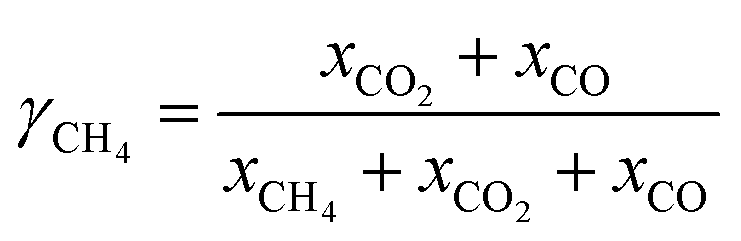
The original experiment defined the reactivity between fuel and OC as the carbon conversion rate of methane at the outlet of FR, as follows:
| |
 | (1) |
xi is the volume fraction of gas species i leaving the dry gases in FR in the total output.
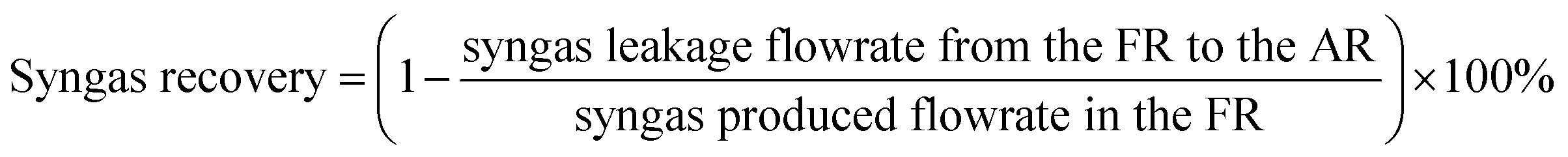
Due to the inherent defects of experimental equipment, there would be inevitably gas leakage in the system. From the gas leakage experiment, it can be learned that about 9 vol% of the gases in FR leaked into AR. There was also the same amount of gases in AR leaking into FR. But in the actual CLR process, the reaction process influenced gas flow, so re-measuring the leakage amount of gas in process was of great significant for process exergy analysis. Through the definition of the recovery rate and purity of syngas, the amount of syngas leaking from FR to AR and the amount of nitrogen leaking from AR to FR can be obtained respectively, as follows:
| |
 | (2) |
| |
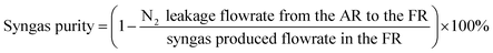 | (3) |
The results of CLR experiment designed by Osman et al. in each case are shown in Table 3.
Table 3 Summary of the main results of the CLR experimental campaigns
| |
Product compositions (vol%) of fuel reactor |
Fuel reactor |
Air reactor |
Syngas recovery% |
Syngas purity% |
T-FR (°C) |
T-AR (°C) |
| CH4 |
CO2 |
CO |
H2 |
N2 |
CH4 conv% |
H2/CO |
O2 conv% |
CO2 vol% |
| Case-3 |
1.7 |
29.2 |
0.4 |
0 |
68.7 |
94.7 |
0 |
28.8 |
0.43 |
88.6 |
90.7 |
764 |
800 |
| Case-4 |
0.8 |
30.3 |
5.7 |
10.5 |
52.6 |
97.8 |
1.83 |
30 |
0.51 |
88.9 |
90.9 |
760 |
810 |
| Case-5 |
0.9 |
31.1 |
10.8 |
22.9 |
34.4 |
98.1 |
2.13 |
34.3 |
0.46 |
91.3 |
93 |
745 |
785 |
| Case-6 |
2.0 |
31.8 |
19.7 |
41.3 |
5.3 |
96.3 |
2.09 |
33.8 |
0.38 |
94.1 |
95.2 |
753 |
793 |
| Case-7 |
1.5 |
19.4 |
14.0 |
31.2 |
33.9 |
95.8 |
2.22 |
96.4 |
0.31 |
93.9 |
94.9 |
746 |
765 |
| Case-8 |
3.4 |
13.9 |
23.7 |
51.1 |
7.9 |
91.7 |
2.16 |
100 |
1.14 |
81.2 |
84.1 |
740 |
765 |
| Case-9 |
3.7 |
19.2 |
15.3 |
51.5 |
10.3 |
90.3 |
3.36 |
23.8 |
0.61 |
87.2 |
89.1 |
721 |
753 |
2.2 Supplementary explanation on the experiment and processing of results
The chemical reactions in the ICR mainly include five heterogeneous catalytic reactions ((R1)–(R4) and (R7)) and two homogeneous catalytic reactions ((R5) and (R6)), as shown below. Among them, (R1) and (R2) serve as the main reactions in the reduction step of the OC, while (R7) serve as the main reaction in the oxidation step of the OC.| | |
CH4 + NiO → CO + 2H2 + Ni
| (R1) |
| | |
CH4 + 4NiO → CO2 + 2H2O(g) + 4Ni
| (R2) |
| | |
H2 + NiO → H2O(g) + Ni
| (R3) |
| | |
CH4 + H2O(g) → CO + 3H2
| (R5) |
| | |
CO + H2O(g) → CO2 + H2
| (R6) |
When the oxidation rate of OC in AR is too low, the solids circulating to FR contained Ni. The methane has a carbon deposition reaction on the catalyst Ni. This not only leads to the deactivation of the OC, but also affects the circulation efficiency of solids.30,31 According to relevant research, the addition of steam can effectively inhibit carbon deposition, especially when the steam/carbon molar rate is greater than 1,32 the reactions are as follows.
Since the internal flow of reactor is substantially stable, it is now assumed that the mass of the OC cycle is a stable value as follows.
| | |
m = mNiO + mNi + mAl2O3 + mC
| (4) |
When calculating the solids circulation rate from FR to AR, the cycle rate of C is zero. The amount of NiO recycled from the FR to the AR is calculated from the CH4/NiO molar ratio and feed quantity of methane. In Cases 3–8, the CH4/NiO molar ratios are 0.27, 0.31, 0.36, 0.45, 0.40 and 0.60, respectively. NiO and Ni are always attached to the inert OC (Al2O3) in a certain molar fraction. In particular, the OC stream circulating to the FR in Case 8 carries a certain amount of Ni, too. When calculating the solids circulation rate from AR to FR, the cycle rate of Ni is obtained from the amount of oxygen-containing gas at the FR outlet. The amount of C is calculated from CO2 at the AR outlet minus the carbon-containing gas leaking into the AR.
2.3 Establishing a thermodynamic model
As a relative quantity different from enthalpy, the value of exergy requires us to select a particular environment as the benchmark. The environmental benchmark is composed of physical benchmark and chemical benchmark. The physical benchmark includes ambient temperature and ambient pressure. So far, the physical benchmark is basically uniform, that is, the benchmark temperature is 298.15 K and the benchmark pressure is 1 atm or 1 bar. The chemical benchmark includes the composition of environmental references and their concentrations in the environment. This is the major difference between different environmental benchmark models. In this study, an advanced Daning Zheng model, defined as follows is referred to:33
(1) The setting of physical benchmark: the benchmark ambient temperature (T0) is 298.15 K and the benchmark ambient pressure (P0) is 1 bar;
(2) The setting of chemical benchmark: the air in the U.S. Standard Atmosphere, 1976 is selected as the reference substance for atmospheric elements. Pure water is selected as the reference substance for hydrogen. While the reference substances of other elements are pure compounds in the earth layer.
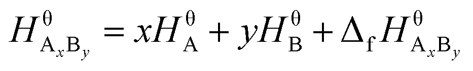
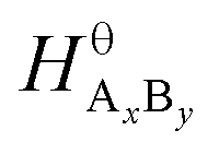
Suppose that the molecular formula of pure substance i is AxBy, then the mathematical models of standard enthalpy and standard exergy of the substance in the reference state are shown in eqn (5) and (6).
| |
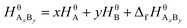 | (5) |
| |
 | (6) |
where

and

are the standard enthalpy and standard exergy of the substance A
xB
y in kJ mol
−1.
Hiθ and
εθi are the standard enthalpy and standard exergy of the element i, in kJ mol
−1.

and

are the standard enthalpy of formation and standard Gibbs free energy of formation of the substance A
xB
y, in kJ mol
−1. The element standard data used in this study are shown in
Table 4. The standard enthalpy of formation and standard Gibbs free energy of formation are consulted from relevant literature.
34
Table 4 Standard enthalpies and exergies for the elements involved33
| Elements |
C |
H |
O |
N |
Ni |
| Standard enthalpy kJ mol−1 |
412.25 |
137.08 |
32.51 |
28.87 |
227.390 |
| Standard exergy kJ mol−1 |
410.51 |
117.60 |
1.94 |
0.31 |
218.475 |
When a material flow composed of a variety of substances change from the reference state to a new state (the system temperature is T and the pressure is P), the mathematical models of material flow enthalpy (Hm) and material flow exergy (Em) in the new state are shown in eqn (7) and (8).
| |
 | (7) |
| |
 | (8) |
where
Hi and
Si are the enthalpy and entropy of the species i in the new state respectively.
Hiθ and
Siθ are the standard enthalpy and standard entropy in the reference state, in kJ mol
−1.
![[f with combining circumflex]](https://www.rsc.org/images/entities/i_char_0066_0302.gif)
and
fiθ are the fugacity and standard fugacity of the species i, in kPa.
Cp and
V are the heat capacity and volume respectively.
N is the total molar flow rate of the material flow, in mol min
−1. Among them, the second terms of
eqn (7) and
(8) can be calculated from the Peng–Robinson equation of state in Aspen Plus.
2.4 Establishing an exergy destruction process model
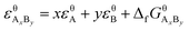
Exergy destruction refers to the system's loss of ability to perform work because of the occurrence of an irreversible process inside the system.
The exergy balance model shown in eqn (9) is used, to analyze the exergy destruction in a steady flow system.
| |
 | (9) |
where
EF,i is the
ith exergy flow input by the system and
EP,j is the
jth exergy flow output by the system.
ED,k is the
kth exergy destruction flow caused by the irreversible process inside the system.
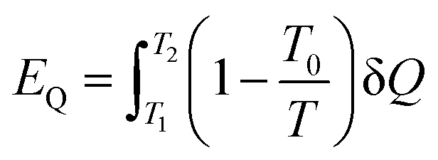
Apart from the material flow exergy mentioned in the previous section, in a common thermodynamic system, there is also workflow exergy and heat flow exergy. The workflow exergy (EW) is equal to the workflow (W) itself, while the heat flow exergy needs to be determined by the initial temperature T1, final temperature T2 and he heat transferred Q in the heat transfer process, as shown in eqn (10) below.
| |
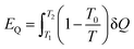 | (10) |
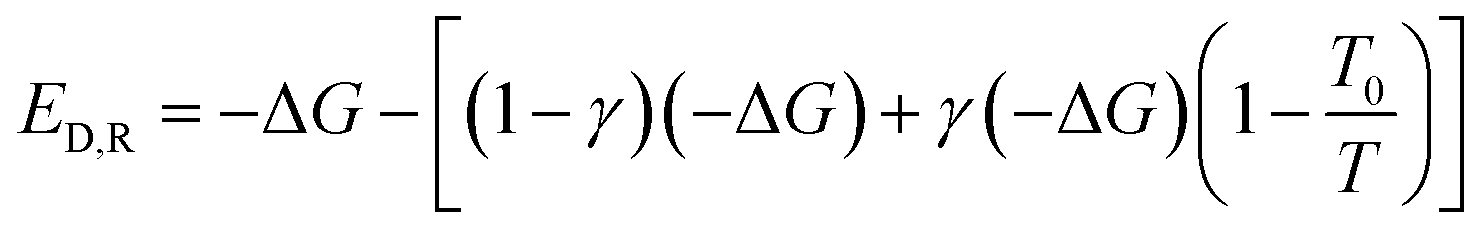
The irreversible processes within a system include chemical reaction processes and physical processes (including flowing process, heat transfer process, mixing & separation process and other processes). All of the Gibbs free energy of chemical reactions involve in the present study under reaction conditions is less than zero. −ΔG stands for the maximum useful work that can be converted in the reversible process of chemical reaction. But in actual cases, part of −ΔG is converted to heat. Suppose that γ stands for the proportion of −ΔG converted to heat in the irreversible process of chemical reaction. Then the exergy destruction during the reaction can be calculated by eqn (11) below. In a special combustion reaction where −ΔG is entirely converted to heat. At this point, γ = 1.
| |
 | (11) |
Since all of the other irreversible processes belong to physical processes. The exergy destruction can be calculated from enthalpy change ΔH and entropy change ΔS during the process, as shown in eqn (12) below.
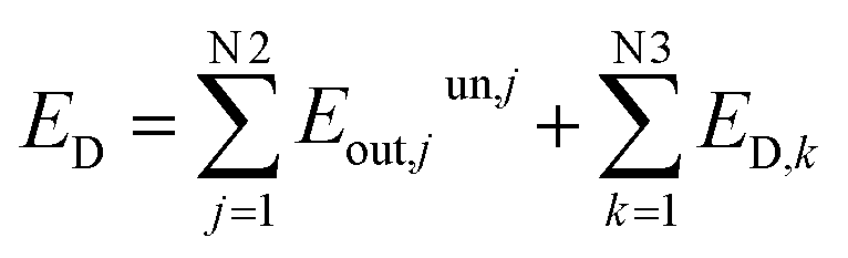
During the operation of system, since the material flow and waste heat discharged are not effectively utilized, some exergy is lost in the irreversible process. This part of exergy destruction is called unused exergy destruction (Eunout). The remaining exergy flow is called benefited exergy flow Ebenout. From here, it can be seen that the total exergy destruction of the system includes exergy destruction caused by the potential difference inside the system and exergy destruction caused by the dissipation effect outside the system, as shown in eqn (13) below.
| |
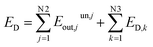 | (13) |
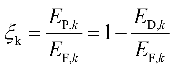
The exergy efficiency of the equipment k or the process k is defined as follows.
| |
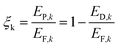 | (14) |
2.5 Establishing an advanced exergetic analysis model
In the chemical looping reaction system, the exergy destructions of AR and FR are not only related to the irreversible process during their own operation, but also related to the energy consumption of the other reactor. For a circulation process, the exergy destruction of each reactor inside the system needs to be analyzed in detail. In an advanced exergetic analysis model, the exergy destruction of reactors can be divided into unavoidable exergy destruction, avoidable exergy destruction, exogenous exergy destruction and endogenous exergy destruction, depending on whether the destruction is avoidable and whether the destruction is caused by internal reasons.
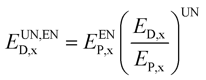
As to the exergy destruction of a given reactor x in the system, the exergy destruction caused by the limitations of technology, economy and other realistic factors are called unavoidable exergy destruction (EUND,x). While the remaining exergy destruction that can be reduced by improving process and equipment are called avoidable exergy destruction (EAVD,x), as shown as follows.
| | |
ED,x = EUND,x + EAVD,x
| (15) |
The calculation of unavoidable exergy destruction relies on the decision-maker's judgement about the optimal running state of system, after taking technology, economy and other constraints into account, so it is somewhat subjective. In the present study, the unavoidable exergy destruction is expressed as the ratio of the exergy destruction and output exergy under the optimal running state of the reactor x and the output exergy (EP,x) in the actual process, as shown below.
| |
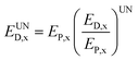 | (16) |
The optimal running state in the CLR experimental process is calculated by simulating using Aspen Plus software from eqn (15) and (16), the calculation model of avoidable exergy destruction can be obtained as below.
| | |
EAVD,x = ED,x − EUND,x
| (17) |
Since the CLR system is a closed looping system, the irreversibility of a certain reactor x in the system is not simply caused by the low efficiency of the reactor itself, but also related to the low efficiency of the other reactor. Considering the interaction between two reactors in the system, the exergy destruction of a given reactor x can be divided into endogenous exergy destruction (EEND,x) and exogenous exergy destruction (EEXD,x), as follows.
| | |
ED,x = EEND,x + EEXD,x
| (18) |
The main ways to calculate endogenous exergy destruction are thermodynamic cycle and engineering methods. Since the ideal operation of equipment and the ideal parameters of cycle cannot be obtained accurately, thermodynamic cycle method had poor calculation accuracy. The engineering method, which is based on the exergy sensitivity analysis of the whole system, is a method that solves using drawings. Although this method has a heavy calculation burden, it is capable of obtaining more accurate results. The calculation model of the engineering drawing method is as follows.
| | |
EF,tot − EP,tot = ED,other + EEND,x
| (19) |
where
EF,tot,
EP,tot and
ED,other are the total input exergy of the system, the total output exergy of the system, and the total exergy destruction of other devices than the reactor x. By drawing of a curve of
EF,tot −
EP,tot with respect to
ED,other, the researchers found that when
ED,other = 0, the intercept of the curve on the
y-axis is equal to the endogenous exergy destruction of the reactor x. From the study of Kelly
et al.,
35 it can be learned that
EF,tot −
EP,tot is linearly correlated with
ED,other. It is noteworthy that when the reactor x is calculated, its running state should remain unchanged, that is, its exergy efficiency must remain unchanged (
ξx = const).
After the division of exergy destruction in reactors, the calculation formulas for unavoidable endogenous exergy destruction (EUN,END,x), unavoidable exogenous exergy destruction (EUN,EXD,x), avoidable endogenous exergy destruction (EAV,END,x) and avoidable exogenous exergy destruction (EAV,EXD,x) are obtained as follows:
| |
 | (20) |
| | |
EUN,EXD,x = EUND,x − EUN,END,x
| (21) |
| | |
EAV,END,x = EEND,x − EUN,END,x
| (22) |
| | |
EAV,EXD,x = EEXD,x − EUN,EXD,x
| (23) |
3 Results and discussion
From eqn (5) and (6), the standard enthalpy and standard exergy of the substance under study can be obtained, as the basic data for exergy analysis, as shown in Table 5.
Table 5 Standard thermodynamic properties of the involved components
| Component |
CH4 |
CO |
CO2 |
H2 |
H2O (g) |
N2 |
O2 |
NiO |
Ni |
| Hθ, kJ mol−1 |
885.97 |
334.26 |
83.77 |
274.16 |
64.87 |
57.74 |
65.02 |
20.20 |
8.82 |
| ξθ, kJ mol−1 |
830.41 |
275.25 |
19.99 |
235.20 |
8.54 |
0.62 |
3.88 |
227.39 |
218.48 |
3.1 Analyzing the system exergy
The CH4/NiO molar ratio is the main factor controlling whether a reaction process is CLR or CLC. Theoretically, when the CH4/NiO molar ratio is less than 0.25, the whole system ran a CLC process. First of all, in Cases 3–6, a sufficient and the same amount of air is fed into AR. The CH4/NiO molar ratio is regulated by changing the feed quantity of methane. Secondly, by comparing Cases 7 and 8 with Cases 5 and 6 respectively, through the regulation of the feed quantity of oxygen, the influence of incomplete oxidation of nickel-based OC on the reforming reaction can be studied. Finally, in Case 9, the addition of steam changed the thermodynamic equilibrium restriction in the reaction system and was a possible path to improve the CLR process.
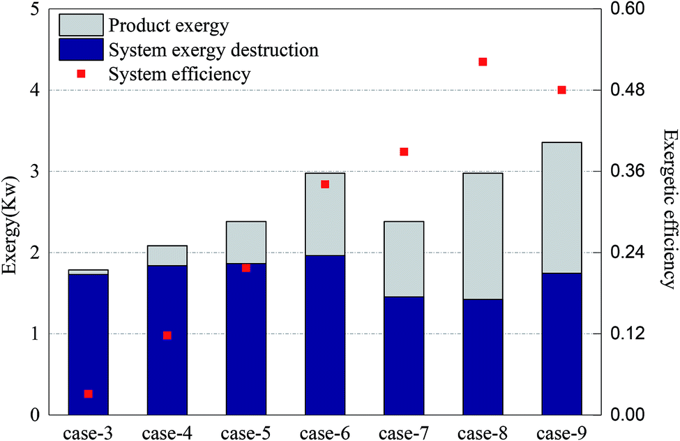
Fig. 4 shows the exergy destruction of the system and product exergy in each case. Initially, with the increase of methane input, the exergy destruction of the system didn't increase significantly. Moreover, through the reduction of air input as appropriate, up to 18% of exergy can be saved. Compared with the addition of steam, the reduction of oxygen input is more conducive to the reduction of the total exergy destruction of the system. In Case 8, the exergy efficiency was the highest, at 52%. From the above, it can be seen that through the increase of the CH4/NiO molar ratio as appropriate, that is, to control CLR process as the main reaction process, the use of exergy can be improved and exergy destruction in the process can be reduced, thereby achieving the efficient use and conversion of energy.
 |
| | Fig. 4 System exergy destruction and product exergy for Cases 3–9. | |
The main product of the CLC process is thermal exergy, while the main product of the CLR process is chemical exergy. Therefore, in the CLR study, the output product exergy referred to the chemical exergy of syngas which is discharged from FR. Since the chemical exergies of nitrogen and carbon dioxide in the syngas are very small, the product exergies are dominated by the chemical exergies of hydrogen, carbon monoxide and methane. In Cases 3–6, the target product of experiment (i.e. syngas) gradually grew and the output product exergy also grew accordingly. Case 3 had an almost complete CLC process and the output exergy of target product is only 0.05 kW. As the most obvious CLR process, the output exergy of target product in Case 6 is about 1.01 kW. In Cases 7 and 8, as the oxidation rate of the OC in AR decreased, the NiO circulating to FR decreased, while the Ni increased. In these two cases, the CLR process is further enhanced. The exergy which hadn't been used originally is converted to product exergy and then output. On the other hand, according to the study of Moayeri et al., Ni can directly catalyze the decomposition of methane into hydrogen and carbon monoxide and also promote the output of product exergy.36 In the comparison between Cases 5 and 9, the addition of steam can significantly increase the product exergy and raise the hydrogen output by about two times.
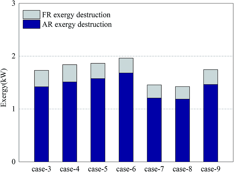
Fig. 5 shows the exergy destruction of AR and the exergy destruction of FR in each case. The exergy destruction of AR accounted for more than 82% of the total exergy destruction of the system. The reaction process in AR is the main exergonic process of the system. The main factors affecting the exergy destruction of AR included the conversion rate of OC in FR and the oxygen input in AR. In Cases 3–6, when the oxygen input in AR was sufficient, a constant amount of NiO reacted with growing methane and produced more Ni. The oxidization of Ni in AR led to more exergy destruction. From the results of Cases 7–8, it can be learned that the circulation of OC at a low oxidation rate can help reduce exergy destruction in the process. But on the other hand, it would also increase deposited carbon (methane was decomposed under the catalysis of nickel). When the deposited carbon was leaked to AR, oxygen would be consumed and further reduce the circulation rate of oxygen in the system, making the system unstable and diminishing the reaction efficiency. Considering the long-term stable operation of the system, there existed a minimum for oxygen input. The addition of a certain amount of steam can effectively inhibit the problem of carbon deposition and reduce the exergy destruction of AR.37
 |
| | Fig. 5 AR exergy destruction and FR exergy destruction for Cases 3–9. | |
As for the exergy destruction of FR, in Cases 3–6, with the increase of the CH4/NiO molar ratio, the combustion process in FR was gradually weakened. In contrast, the reforming process was gradually enhanced. The enhancement of reforming process can reduce the exergy destruction inside the reactor. In Case 4, the exergy destruction of FR reached a maximum of 0.33 kW. In Cases 7 and 8, the exergy destruction of FR further decreased. On the one hand, the decrease of the CH4/NiO molar ratio in the system can further enhance the reforming reaction. On the other hand, the decrease of the conversion rate of methane can also diminish the exergy destruction of FR.
3.2 Analyzing the reactor exergy
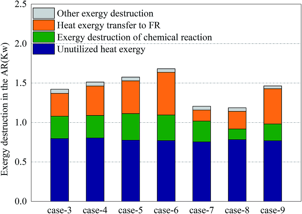
Fig. 6 shows the distribution of exergy destruction of AR in each case. In AR, the exergy destruction occurred in the exhaust cooling process, chemical reaction process heat transfer process and other processes (including flowing process, mixing & separation process and dissipation process, etc.). First of all, the unused thermal exergy referred to the thermal exergy of reactor exhaust which is lost and dissipated in the cooler, which was mainly related to the outlet temperature and exhaust volume. Since no heat recovery unit was set up in the reactor, an abundance of thermal exergy cannot be effectively used, making the thermal exergy in the exhaust become the greatest part of the exergy destruction of AR. Meanwhile, since there is no significant difference in terms of outlet temperature and exhaust volume, the unused thermal exergy fluctuated around 0.78 kW. Secondly, the exergy destruction in the chemical reaction process had a direct bearing with the conversion rate of oxygen. With sufficient oxygen, the conversion rate of oxygen in Case 5 reached the maximum, 34.3%, which corresponded to the maximum exergy destruction of 0.34 kW in the chemical reaction process. Although the conversion rate in Case 8 was the highest, the oxygen input was still relatively low, so the exergy destruction in the chemical reaction process in Case 8 was still relatively small. The thermal exergy transferred to FR was mainly used to support the endothermic reaction in FR and associated with the conversion of methane in FR and the reaction temperature in AR. This part of thermal exergy was mainly transferred through the OC and reactor wall. In Cases 3–6 and Cases 7–8, with the increase of conversion rate of methane, more and more thermal exergy was transferred to FR. Moreover, in the comparison between Cases 5 and 7, Cases 6 and 8, the thermal exergy transferred to FR was mainly related to the reaction temperature and conversion rate of methane in AR. In the comparison between Cases 5 and 9, as the addition of steam introduced thermal exergy to the reactor, the thermal exergy transferred from AR to FR in Case 9 decreased. Finally, the exergy destruction of other processes was mainly related to the flow inside the reactor. Since the flow somewhat fluctuated during the experiment, the value of exergy destruction would slightly change within a certain range.
 |
| | Fig. 6 Exergy destruction distribution in the AR for Cases 3–9. | |
Fig. 7 shows the distribution of exergy destruction of FR in each case. First of all, the unused thermal exergy in FR was consistent with the above definition. Since the exhaust of FR is about 0.2 times that of AR, the unused thermal exergy would also decrease accordingly. In Case 8, the reaction temperature in FR was low, while the leakage amount of syngas was large, so its unused thermal exergy was the smallest, at 0.14 kW. Secondly, the exergy destruction in the chemical reaction process was mainly influenced by the reacting dose of methane and the CH4/NiO molar ratio. In Case 4, when the maximum exergy destruction of 0.13 kW was reached, with the increase of the CH4/NiO molar ratio, the exergy destruction in the chemical reaction process would gradually decrease. The main reaction in FR was an endothermic reaction. And then, when being transferred to FR, this high-temperature heat from AR had a temperature difference, thus leading to exergy destruction. Such destruction decreased with the decrease of temperature difference. In Cases 7 and 8, the temperature differences between two reactors were relatively small and the exergy destructions in the process were 0.001 kW and 0.002 kW respectively. Finally, the exergy destructions of other processes and unused thermal exergy exhibited the same trend in FR and AR.
 |
| | Fig. 7 Exergy destruction distribution in the FR for Cases 3–9. | |
3.3 Analyzing process exergy in chemical reactions
Fig. 8 shows the distribution of exergy destruction of chemical reactions in AR. The chemical reactions in AR included the oxidation of nickel and the oxidation of other substances (e.g. coke, hydrogen and carbon monoxide) leaked from FR. The oxidation of nickel served as a combustion reaction. From eqn (7), it is can be seen that the exergy destruction per mole was related to the reaction temperature and Gibbs free energy. The equilibrium temperature for the oxidation of nickel is 2762 °C (from HSC Chemistry software). Therefore, the increase of reaction temperature was beneficial to the reduction of exergy destruction in the reaction process. Since the system ran at a constant pressure, the exergy destruction per mole was merely a function of temperature.
 |
| | Fig. 8 Exergy destruction distribution of chemical reaction in the AR for Cases 3–9. | |
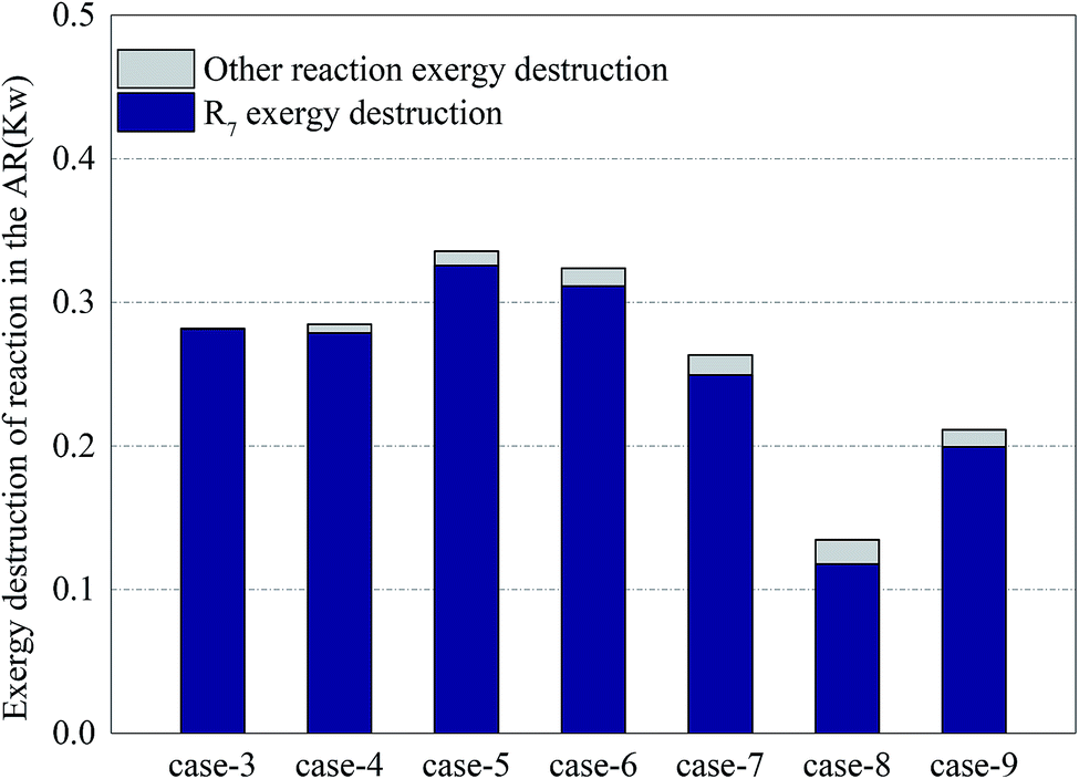
In all cases, the exergy destruction in the oxidation process of nickel presented an unstable variation trend. When the methane input increased, on the one hand, the amount of nickel oxide reacting with methane increased. On the other hand, due to the enhancement of the CLR process, the amount of nickel oxide consumed per mole methane decreased. In Case 5, the exergy destruction in the oxidation process of nickel reached a maximum of 0.33 kW. In Case 8, due to insufficient oxygen input, nickel was not completely oxidized and the exergy destruction in the process was diminished. On the other hand, the increase of exergy destruction of other reaction processes can be interpreted as that the deposited carbon that leaked into AR increased and led to the intensified oxidation of deposited carbon. This conclusion can be proved by the concentration of CO2 in the exhaust of AR. In Case 9, the addition of steam can eliminate deposited carbon to a certain extent, but due to the increase of hydrogen yield in FR, the hydrogen concentration in the leaked gas grew. The oxidation process of hydrogen in AR enlarged the exergy destruction of other reaction processes.
Fig. 9 shows the distribution of exergy destruction of chemical reactions in FR in each case. In order to study the influence of various operations on major reactions in FR, the author divided the exergy destructions in various reaction processes in FR into exergy destruction in reforming process, exergy destruction in combustion process and exergy destruction in other reaction processes. Through a comparison of exergy destructions in various reaction processes, the reaction statuses of two major reactions under various operating conditions can be distinguished. A low CH4/NiO molar ratio can enhance the CLR process and diminish the exergy destruction of reactors. The main reason was that when a unit quantity of methane had a reforming reaction on NiO, the exergy destruction accounted for 33.9%–37.2% of the exergy destruction in combustion reaction. But on the other hand, a low CH4/NiO molar ratio would also facilitate the exergy destruction in other reaction processes. This was mainly attributed to the intensified decomposition of methane under the catalysis of nickel. Due the limitation of thermal balance, the CLR process had the maximum extent of reaction. When the CLR process was the most intense, the exergy destruction was 0.04 kW. Through a comparison of Cases 5 and 9, the addition of steam can facilitate the CLR process, as well as the reforming of methane steam.
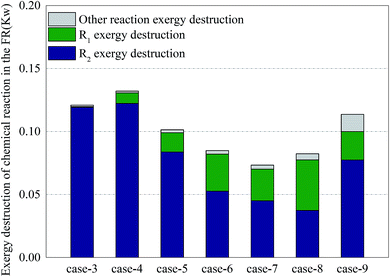 |
| | Fig. 9 Exergy destruction distribution of chemical reaction in the FR for Cases 3–9. | |
3.4 Advanced exergetic analysis
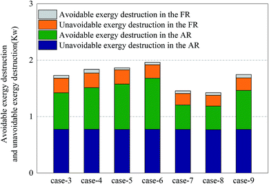
For the division of unavoidable exergy destruction and avoidable exergy destruction, the results are shown in Fig. 10. All cases deviated from the assumed working conditions in AR at almost the same degree, so their unavoidable exergy destructions were almost equal. On the other hand, the avoidable exergy destruction of AR was associated with the utilization of heat. In Cases 7 and 8, due to the enhancement of the CLR process in FR, the heat in AR was converted to the chemical exergy of the product, rather than being wasted by the cooler. So the avoidable exergy destruction obviously decreased. The unavoidable exergy destruction of FR reached the maximum, 0.26 kW in Case 4 and was mainly related to the situation of chemical reactions. The unavoidable exergy destruction of FR was relatively small, so it will be not be elaborated on in the optimization process.
 |
| | Fig. 10 Avoidable exergy destruction and unavoidable exergy destruction for Cases 3–9. | |
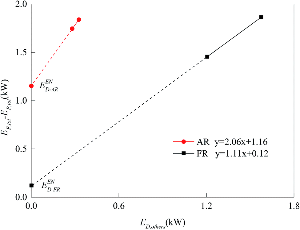
When the endogenous exergy destruction was calculated using engineering method, the running state of the reactor x must remain unchanged. When the endogenous exergy destruction of AR was calculated, Cases 4 and 9 were selected for calculation (i.e., to regulate the feed of FR). When the endogenous exergy destruction of FR was calculated, Cases 5 and 7 were selected for calculation (i.e., to regulate the feed of AR). The relationship curves between EF,tot − EP,tot and ED,other for two reactors are shown in Fig. 11. Through the intercepts of various straight lines on the y-axis, the endogenous exergy destructions of various reactors can be obtained.
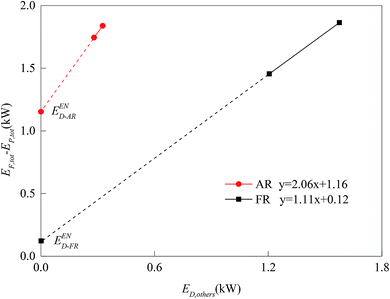 |
| | Fig. 11 Diagram of EF,tot − EP,tot vs. ED,other for CLR process components. | |
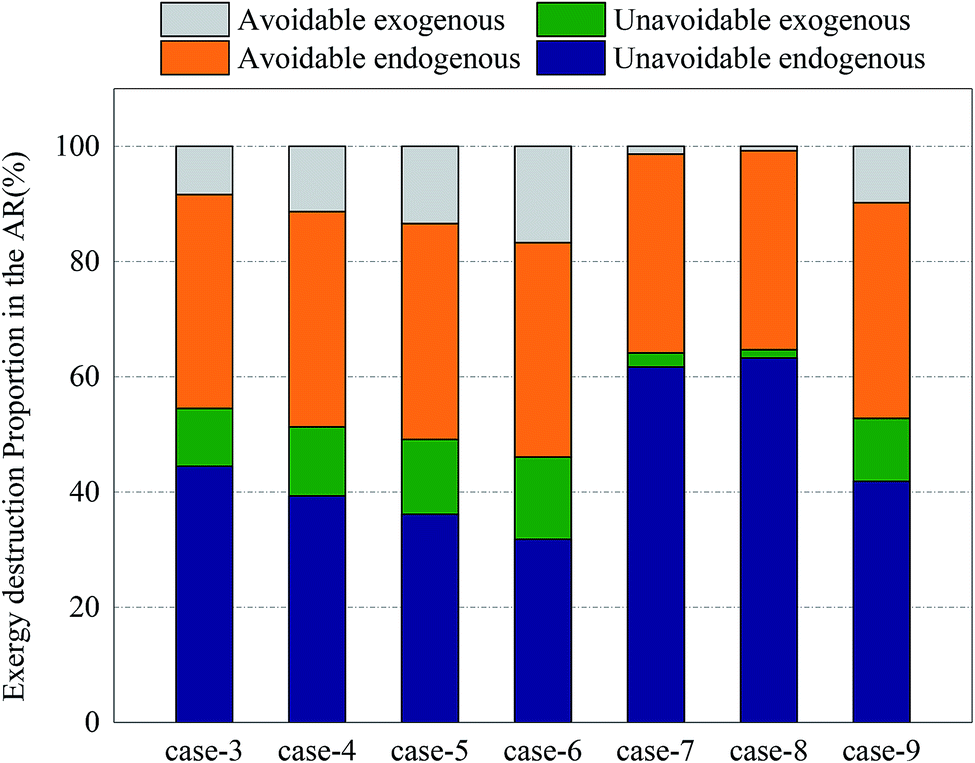
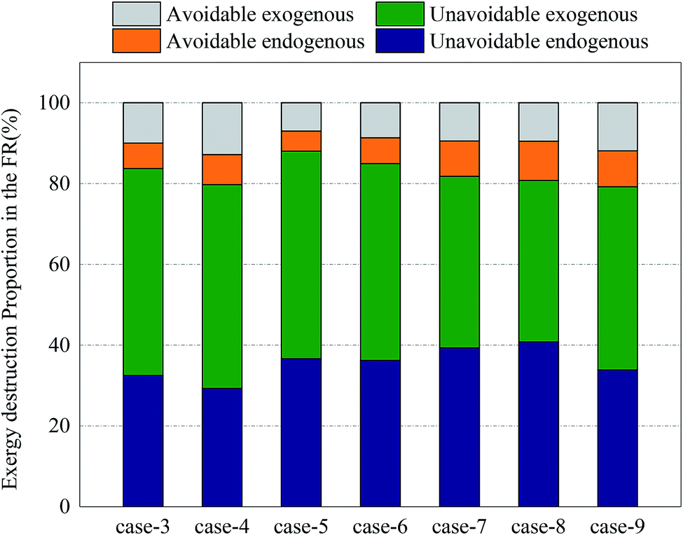
Fig. 12 and 13 shows the proportions of all kinds of exergy destructions of AR and FR. In AR, most of the exergy destructions were endogenous, indicating that the reactions in FR had little influence on the exergy destructions of AR, while the reactions in AR had great influence on the exergy destructions of FR. This was because oxygen circulating to FR was one of the major variables that directly controlled the reaction processes in FR. Through the adjustment of operating parameters in AR, the exergy destructions of FR can be effectively reduced.
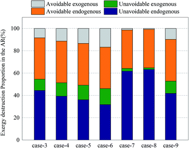 |
| | Fig. 12 Splitting of component exergy destruction to endogenous/exogenous and avoidable/unavoidable parts: AR. | |
 |
| | Fig. 13 Splitting of component exergy destruction to endogenous/exogenous and avoidable/unavoidable parts: FR. | |
In AR, the avoidable endogenous exergy destruction and unavoidable endogenous exergy destruction accounted for a vast majority of exergy destruction. In the calculation of avoidable endogenous exergy destruction, the cooler that treated exhaust was incorporated in the calculation of reactor. The heat discharge in AR was large, so the avoidable endogenous exergy destruction accounted for a large proportion. This part of exergy destruction can be reduced by adding a heat exchanger to recover heat. The unavoidable endogenous exergy destruction was mainly induced by the low efficiency of chemical reactions. This part of exergy destruction can be reduced by replacing the OC or changing the operating conditions, but restricted by technology and economy. If the reaction pressure and the reaction temperature were increased blindly, the equipment investment would be increased. This deviated from realistic conditions. The avoidable exogenous exergy destruction of AR was caused by the avoidable low efficiency of FR and accounted for up to 16.7%. The unavoidable exogenous exergy destruction of AR can be controlled by regulating the reaction process in FR. The more intense the CLR process in FR, the smaller value the unavoidable exogenous exergy destruction had.
In FR, the unavoidable endogenous exergy destruction and unavoidable exogenous exergy destruction accounted for a vast majority of exergy destruction. Both the reforming reaction and OC reduction reaction in the reactor were endothermic reactions, this part of exergy destruction during reactions was a necessary price for the procession of reactions, the reaction processes in FR were directly influenced by the OC transferred from AR, and the influence factors included the oxygen content and heat carried by the OC. So the unavoidable exogenous exergy destruction accounted for a relatively large proportion. Similarly, the avoidable endogenous exergy destruction can also be reduced by replacing the OC or changing the operating conditions, although the reducible range was small. The avoidable exogenous exergy destruction can be reduced by regulating the reaction temperature and circulation rate of solids in AR.
According to the results of the advanced exergetic analysis of AR and FR, the optimization directions for the improvement of the exergy efficiency of ICR can be determined.
(1) For the avoidable endogenous exergy destruction caused by the underutilization of thermal exergy in exergy destruction of AR, it is considered to carry out heat exchange treatment between the high-temperature exhaust in AR and material inflow in FR. The optimization by adding a heat exchanger can also reduce the avoidable exogenous exergy destruction of FR caused by the transfer of thermal exergy.
(2) For the unavoidable endogenous exergy destruction caused by the limited utilization efficiency of chemical reactions as a result of the redox nature of the OC, the optimization can be achieved by replacing the OC.
3.5 Evaluation
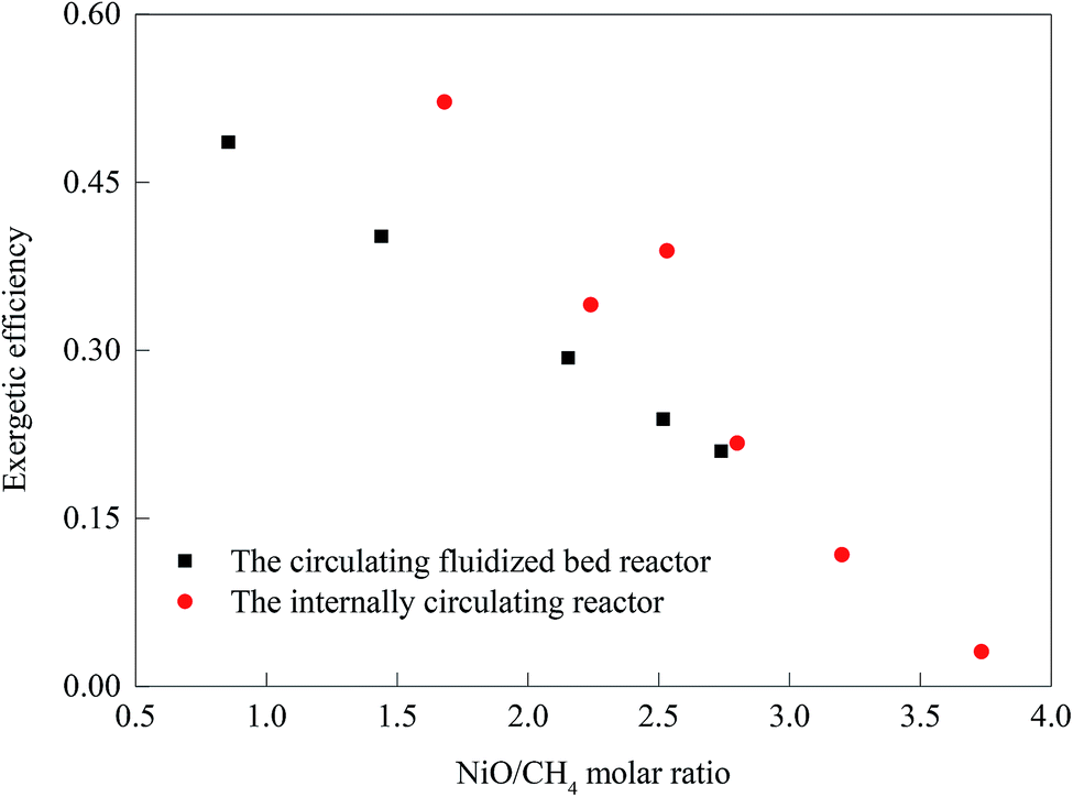
The research done by Luis F. et al. on hydrogen production by chemical-looping reforming in a CFBR was compared with ICR experiments in Cases 3–8. The results are shown in the figure.38 With the decrease of the NiO/CH4 molar ratio, the ICR exhibited higher utilization efficiency of exergy. There were three main reasons for this: (1) compared with the single heat transfer mode of the CFBR, the ICR not only transferred heat through the OC, but also through the direct contact of reactor wall, thereby realizing the efficient use of heat; (2) compared with the complex and long delivery pipeline of the CFBR, the flow mode of ICR was simple and fast; (3) the ICR can work at an operating condition higher than the normal pressure (Fig. 14).
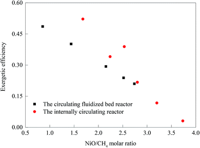 |
| | Fig. 14 The efficiency of the CFBR and the ICR at different carrier-to-fuel radios. | |
The advantages of ICR's pressurization operation are obvious, but its main disadvantages cannot be ignored. Gas leakage not only affects the purity and recovery of the syngas produced, but also reduces the capture rate of CO2 and increases the system's exergy destruction. Too high gas fluidization velocity will result in increased gas leakage, while too low gas fluidization velocity will result in the inability to achieve the necessary solid recycle rate.
With increasing demand for hydrogen in fuel cells, petrochemicals, aerospace and other fields, the production of high-purity hydrogen has become more and more important. However, it is clear that in the application of ICR in hydrogen production, like the traditional hydrogen production process, the purification device required for the subsequent steps still cannot be got rid of. This is related to the ICR being designed to be suitable for the CLR process at the beginning of the design. Chemical looping hydrogen generation (CLH) is a hydrogen production technology that does not require hydrogen purification and carbon capture processes, which can significantly simplify subsequent operations and reduce costs.39,40 Therefore, in the future, ICR should be improved to a three-cavity reactor suitable for the CLH process.
The study of the thermodynamic properties of ICR provides a specific approach and achievable goals for the improvement of ICR reactors. According to research results, it can be concluded that the system operating at high CH4/NiO molar rate has higher exergy efficiency. The addition of steam has a slight benefit in the improvement of the system. Enthusiastic effective recovery plays an important role in the reduction of exergy destruction. The development of more efficient OCs is also a way to reduce exergy destruction.
4 Conclusion
As a novel reactor suitable for chemical looping processes, ICR has not been studied in terms of thermodynamic properties. In this paper, the exergy efficiency of a methane autothermal chemical looping reforming experiment carried out on an ICR is evaluated by establishing a mathematical analysis model and the exergy destruction in all processes of each reactor during of the experiment are analyzed in detail. Through the model, the specific processes and main source of exergy destructions can be obtained. The established thermodynamic exergy destruction evaluation model is also adapted to other reactors. The present study provides optimization guidance for the design of reactors and the operation of reactors.
A high CH4/NiO molar ratio can increase the output exergy of product and reduce the exergy destruction of the whole system, which suggests that the CLR process has higher energy efficiency than the CLC process. AR contributes to most of the exergy destruction of the system and has much room for improvement. Since all reaction processes in the AR are exothermic, it is particularly important to use thermal exergy effectively. Some of the thermal exergy generated is transferred to the FR to support the procession of reactions, while some are discharged from the AR, along with the unreacted air. The thermal exergy transferred to the FR is related to the reaction path of methane. The unused thermal exergy accounts for the largest part of the exergy destruction inside the reactor. The FR receives thermal exergy from the AR. In the process of chemical reactions, with the decrease of the CH4/NiO molar ratio, the exergy destruction gradually decreases. This is because when a unit quantity of methane has a reforming reaction on NiO, the exergy destruction accounts for 33.9%–37.2% of the exergy destruction in combustion reaction.
An advanced exergetic analysis is used to study the main source of exergy destructions inside the reactor. In the AR, the avoidable endogenous exergy destruction and unavoidable endogenous exergy destruction account for a large proportion, so to improve the design of the reactor becomes its main optimization direction. In the FR, the unavoidable endogenous exergy destruction and unavoidable exogenous exergy destruction account for a large proportion, so to optimize the design of chemical reaction becomes its main optimization direction. Based on the above two directions, two solutions have been proposed, i.e., to add a heat recovery unit and to develop a more efficient OC.
Conflicts of interest
There are no conflicts to declare.
References
- H. Kim, et al., Economic evaluation of syngas production: model development and analysis, Trans. ASABE, 2012, 55(55), 1033–1045 Search PubMed.
- Q. Fu, et al., Syngas production via high-temperature steam/CO2 co-electrolysis: an economic assessment, Energy Environ. Sci., 2010, 3(10), 1382 RSC.
- K. Aasberg-Petersen, et al., Natural gas to synthesis gas – catalysts and catalytic processes, J. Nat. Gas Sci. Eng., 2011, 3(2), 423–459 CrossRef CAS.
- K. O. Christensen, et al., Effect of supports and Ni crystal size on carbon formation and sintering during steam methane reforming, Appl. Catal., A, 2006, 314(1), 9–22 CrossRef CAS.
- L. Barelli, et al., Hydrogen production through sorption-enhanced steam methane reforming and membrane technology: a review, Energy, 2008, 33(4), 554–570 CrossRef CAS.
- A. Nandy, et al., Present status and overview of chemical looping combustion technology, Renewable Sustainable Energy Rev., 2016, 59, 597–619 CrossRef.
- J. Adanez, et al., Progress in Chemical-Looping Combustion and Reforming Technologies, Prog. Energy Combust. Sci., 2012, 38(2), 215–282 CrossRef CAS.
- M. Rydén and A. Lyngfelt, Using steam reforming to produce hydrogen with carbon dioxide capture by chemical-looping combustion, Int. J. Hydrogen Energy, 2006, 31(10), 1271–1283 CrossRef.
- A. Lyngfelt, L. Bo and T. Mattisson, A fluidized-bed combustion process with inherent CO2 separation; application of chemical-looping combustion, Chem. Eng. Sci., 2001, 56(10), 3101–3113 CrossRef CAS.
- M. Ortiz, et al., Hydrogen production by auto-thermal chemical-looping reforming in a pressurized fluidized bed reactor using Ni-based oxygen carriers, Int. J. Hydrogen Energy, 2010, 35(1), 151–160 CrossRef CAS.
- T. Pröll, et al., Syngas and a separate nitrogen/argon stream via chemical looping reforming – A 140 kW pilot plant study, Fuel, 2010, 89(6), 1249–1256 CrossRef.
- M. Rydén, A. Lyngfelt and T. Mattisson, Synthesis gas generation by chemical-looping reforming in a continuously operating laboratory reactor, Fuel, 2006, 85(12), 1631–1641 CrossRef.
- J. Adánez, et al., Selection of Oxygen Carriers for Chemical-Looping Combustion, Energy Fuels, 2004, 18(2), 371–377 CrossRef.
- M. Ishida and H. G. Jin, A new advanced power-generation system using chemical-looping combustion, Energy, 1994, 19(4), 415–422 CrossRef CAS.
- N. Berguerand and A. Lyngfelt, Design and operation of a 10 kW chemical-looping combustor for solid fuels – testing with South African coal, Fuel, 2008, 87(12), 2713–2726 CrossRef CAS.
- S. R. Son and D. K. Sang, Chemical-Looping Combustion with NiO and Fe2O3 in a Thermobalance and Circulating Fluidized Bed Reactor with Double Loops, Ind. Eng. Chem. Res., 2006, 45(45), 2689–2696 CrossRef CAS.
- D. Feng, et al., Results of Bituminous Coal Gasification upon Exposure to a Pressurized Pilot-Plant Circulating Fluidized-Bed (CFB) Reactor, Energy Fuels, 2010, 24(5), 3150–3158 CrossRef.
- M. RydéN, A. Lyngfelt and T. Mattisson, Chemical-Looping Combustion and Chemical-Looping Reforming in a Circulating Fluidized-Bed Reactor Using Ni-Based Oxygen Carriers, Energy Fuels, 2008, 22(4), 2585–2597 CrossRef.
- A. Zaabout, et al., Experimental Demonstration of a Novel Gas Switching Combustion Reactor for Power Production with Integrated CO2 Capture, Ind. Eng. Chem. Res., 2013, 52(39), 14241–14250 CrossRef CAS.
- W. Wang, Y. Cao and Y. Wang, Natural gas fuelled chemical looping reforming with carbon dioxide capture technology for hydrogen generation: thermodynamic investigation, J. Energy Inst., 2016, 84(2), 94–101 CrossRef.
- M. N. Khan and T. Shamim, Techno-economic assessment of a plant based on a three reactor chemical looping reforming system, Int. J. Hydrogen Energy, 2016, 41(48), 22677–22688 CrossRef CAS.
- B. Jin, Gas-Solid Flow Behavior in a Pressurized High-Flux Circulating Fluidized Bed Riser, Chem. Eng. Commun., 2014, 201(3), 352–366 CrossRef.
- X. Rui, et al., Pressurized chemical-looping combustion of coal using an iron ore as oxygen carrier in a pilot-scale unit, Int. J. Greenhouse Gas Control, 2012, 10(5), 363–373 Search PubMed.
- L. M. Cheng and P. Basu, Effect of pressure on loop seal operation for a pressurized circulating fluidized bed, Powder Technol., 1999, 103(3), 203–211 CrossRef CAS.
- S. Cloete, A. Zaabout and S. Amini, The Internally Circulating Reactor (ICR) Concept Applied to Pressurized Chemical Looping Processes, Energy Procedia, 2017, 114, 446–457 CrossRef CAS.
- A. Zaabout, S. Cloete and S. Amini, Innovative Internally Circulating Reactor Concept for Chemical Looping-Based CO2 Capture Processes: Hydrodynamic Investigation, Chem. Eng. Technol., 2016, 39(8), 1413–1424 CrossRef CAS.
- Z. Wang, et al., Exergy analysis of methane cracking thermally coupled with chemical looping combustion for hydrogen production, Appl. Energy, 2016, 168, 1–12 CrossRef CAS.
- S. Mukherjee, et al., Energy and exergy analysis of chemical looping combustion technology and comparison with pre-combustion and oxy-fuel combustion technologies for CO2 capture, J. Environ. Chem. Eng., 2015, 3(3), 2104–2114 CrossRef CAS.
- M. Osman, et al., Internally circulating fluidized-bed reactor for syngas production using chemical looping reforming, Chem. Eng. J., 2018 DOI:10.1016/j.cej.2018.10.013.
- L. U. Yao, et al., Research on the carbon deposition characteristics of the metal oxygen carrier, J. China Coal Soc., 2012, 37(2), 328–331 Search PubMed.
- L. F. D. Diego, et al., Synthesis gas generation by chemical-looping reforming in a batch fluidized bed reactor using Ni-based oxygen carriers, Chem. Eng. J., 2008, 144(2), 289–298 CrossRef.
- S. M. Nazir, et al., Techno-economic assessment of the novel gas switching reforming (GSR) concept for gas-fired power production with integrated CO2 capture, Int. J. Hydrogen Energy, 2018, 43(18), 8754–8769 CrossRef CAS.
- D. Zheng, et al., Energy quality factor of materials conversion and energy quality reference system, Appl. Energy, 2017, 185, 768–778 CrossRef CAS.
- W. M. Haynes, CRC Handbook of Chemistry and Physics, 2011 Search PubMed.
- S. Kelly, G. Tsatsaronis and T. Morosuk, Advanced exergetic analysis: approaches for splitting the exergy destruction into endogenous and exogenous parts, Energy, 2009, 34(3), 384–391 CrossRef.
- M. Moayeri and D. L. Trimm, Effect of carbon deposition on the activity of steam reforming catalysts, J. Chem. Technol. Biotechnol., Biotechnol., 2010, 26(1), 419–424 Search PubMed.
- R. Kaczmarczyk and S. Gurgul, Model Approach of Carbon Deposition Phenomenon in Steam and Dry Methane Reforming Process, Arch. Metall. Mater., 2014, 59(1), 145–148 CAS.
- L. F. de Diego, et al., Hydrogen production by chemical-looping reforming in a circulating fluidized bed reactor using Ni-based oxygen carriers, J. Power Sources, 2009, 192(1), 27–34 CrossRef CAS.
- H. J. Ryu and G. T. Jin, Performance Estimation and Process Selection for Chemical-Looping Hydrogen Generation System, Korean J. Chem. Eng., 2007, 24(3), 527–531 CrossRef CAS.
- S. Chen, et al., Experimental investigation of chemical looping hydrogen generation using iron oxides in a batch fluidized bed, Proc. Combust. Inst., 2011, 33(2), 2691–2699 CrossRef CAS.
|
| This journal is © The Royal Society of Chemistry 2019 |
Click here to see how this site uses Cookies. View our privacy policy here. 
 Open Access Article
 This Open Access Article is licensed under a Creative Commons Attribution-Non Commercial 3.0 Unported Licence
 ,
Lin Zhu* and
Dong Rao
,
Lin Zhu* and
Dong Rao


 and
and 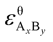 are the standard enthalpy and standard exergy of the substance AxBy in kJ mol−1. Hiθ and εθi are the standard enthalpy and standard exergy of the element i, in kJ mol−1.
 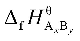 and
and 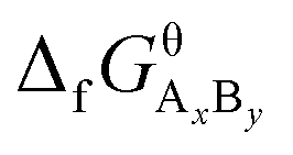 are the standard enthalpy of formation and standard Gibbs free energy of formation of the substance AxBy, in kJ mol−1. The element standard data used in this study are shown in Table 4. The standard enthalpy of formation and standard Gibbs free energy of formation are consulted from relevant literature.34