DOI:
10.1039/C9RA03310F
(Paper)
RSC Adv., 2019,
9, 18803-18813
Monometallic and bimetallic Cu–Ag MOF/MCM-41 composites: structural characterization and catalytic activity
Received
3rd May 2019
, Accepted 7th June 2019
First published on 14th June 2019
1 Introduction
Nanoporous metal–organic frameworks (MOFs) have received more attention due to their attractive properties such as high surface area, high porosity, low density and crystalline character as well as their composition and chemical structure.1–3 Therefore, MOFs used in various applications involving chemical separation,4 gas adsorption and storage,5 drug delivery,6 luminescence,7 biomedical imaging8 and used in many reactions as a catalyst.9 There is a strong host–guest interaction in the MOF between the metal nanoparticles and the framework via coordination and π–π forces which depend on its electronic properties and structure that in turn enhance the catalytic activity and stability.10–12 MOF catalysts are nontoxic, inexpensive, have very high activity and selectivity, and can be separated easily from the reaction mixture and reused.13 Nano MOFs often exhibit some additional chemical and physical properties, without changing the material composition, which differs from usual inorganic metal oxides.14 Numerous methods have been used to control the shape and the size of MOF crystals, such as hydrothermal/solvothermal treatment,15 ultrasonic synthesis,16 microwave heating17 and reverse microemulsion.18 MOFs have been used as solid catalysts for some organic reactions as biodiesel production,19 cyanosilylation of aldehydes,20 synthesis of coumarins,21 catalytic degradation of o/m/p-nitrophenol,22 synthesis of indolizines through aldehyde–amine–alkyne couplings,23 synthesis of 1,5-benzodiazepine,24 Biginelli reaction,25 oxidation,26 aza-Michael condensation27 and so on. However, due to the low thermal stability and processability of MOFs, the practical applications of them are limited.28,29 Also, the dispersive forces for some MOFs are weak due to the high amount of void spaces.30 To overcome these disadvantages, composites have been prepared by combining MOFs with other substrates31,32 as graphene,33 carbon nanotubes,34 activated carbon,35 metals36 and silica.37 Composites are considered as multicomponent materials which have special properties and many applications in the removal of pollutants and in the catalysis field.38 Zhou et al. prepared a composite from three different MOFs and SBA-15 which enhanced the thermal stability of MOFs and increased the decomposition temperature from 318 to 350 °C.39
Hexagonal mesoporous MCM-41 materials has been discovered in 1992 as a member of the M41s family, family of siliceous materials, which possess some properties as large pore volume, large pore size (2–50 nm), controlled pore geometries, well-defined structure, uniform size distribution and high surface area (up to 1000 m2 g−1).40 Therefore, MCM-41 materials applied in many fields as catalysts or catalyst supports.41,42 The integration of MOFs on mesoporous materials as MCM-41 would produce multiple interfaces, which created synergistic effects from multiple components by integration of more than two active sites such as bimetallic or multimetallic catalysts which improve the catalytic activity.43
Amidoalkyl naphthol derivatives are one of the multicomponent reactions (MCRs) which have a great importance nowadays because of their essential role in organic synthesis as formation of desired products in a single synthetic process without any separation problems which in role show high atom economy and high selectivity.44 Amidoalkyl naphthol derivatives have many biological applications such as bradycardiac, antibacterial and hypotensive activities.45,46
Herein, we prepared composites of monometallic and bimetallic MOFs with MCM-41 to combine both properties of metal–organic frameworks and mesoporous materials in these composites.3 Also, we studied their role in the formation of 1-amidoalkyl-2-naphthols.
2 Experimental
2.1. Materials
Terephthalic acid (H2BDC) (98%) was purchased from ALPHA CHEMICA. Pure Cu(NO3)2·3H2O, AgNO3, N,N-dimethylformamide (99.8%), tetra ethyl orthosilicate (TEOS), ammonium hydroxide (28%), benzamide, acetonitrile, n-butyl amine, pyridine, β-naphthol benzaldehyde and cethyltrimethylammoniumbromide (CTAB) were provided from Merck.
2.2. Catalyst preparation
2.2.1. Preparation of Cu-MOF/MCM-41 and Ag-MOF/MCM-41 composites. MCM-41 was prepared according to our previous literature.47 Cu-MOF/MCM-41 and Ag-MOF/MCM-41 composites were achieved by the solvothermal method48 as following: 0.4832 g (2 mmol) of Cu(NO3)2·3H2O or 0.3397 g (2 mmol) of AgNO3 and 0.3323 g (2 mmol) of terephthalic acid were dissolved in 40 ml of DMF solvent, then 10 ml distilled water containing 0.05 g MCM-41 was added and the mixture was stirred for 30 min. The two mixtures were transferred into two autoclaves and heated at 140 °C for 10 h. After cooling to room temperature, the precipitates were filtered and washed several times with DMF followed by drying under vacuum at 120 °C for 6 h. Finally, the blue powder of Cu-MOF/MCM-41 and gray powder of Ag-MOF/MCM-41 composites were obtained.
2.2.2. Preparation of bimetallic Cu–Ag MOF and Cu–Ag MOF/MCM-41 composite. In the same procedures, Cu–Ag MOF was prepared by mixing 0.2416 g (1 mmol) of Cu(NO3)2·3H2O, 0.1699 g (1 mmol) of AgNO3 and 0.3323 g (2 mmol) of terephthalic acid and dissolved in 40 ml DMF solvent while Cu–Ag MOF/MCM-41 composite was prepared by mixing the same amounts with suspension of 0.05 g MCM-41.
2.3. Characterization techniques
FT-IR spectra were measured on the Thermo SCIENTIFIC (NICOLET iS10). The samples were mixed with dry KBr to be analyzed and then scanned from 400 to 4000 cm−1. XRD patterns were collected on a PW 150 (Philips) using Ni-filtered Cu Kα radiation (λ = 1.540 Å) from 2θ of 4 to 80° at 40 kV. The morphology and the elements of the prepared samples were examined via SEM (Scanning Electron Microscopy) and EDX (Energy-Dispersive X-ray Spectroscopy) analysis with the JEOL (Model JSM-6510LV SEM) scanning electron microscope. Before the analysis the samples were coated with gold. To study the binding energies, X-ray photoelectron spectroscopic (XPS) was collected on K-alpha (Thermo Fisher Scientific, USA) with monochromatic X-ray Al K-alpha radiation (−10 to 1350 eV). The surface area of the prepared catalysts was determined by nitrogen adsorption measurement apparatus at −196 °C after degassing at 250 °C for 4 h under a pressure of 10−5 torr.
2.4. Acidity measurements
The total number of acid sites of the solid samples was determined by potentiometric titration.49 0.03 g of the solid catalyst activated at 120 °C for 2 h under vacuum was suspended in 20 ml acetonitrile under stirring for 3 h. The suspension was then titrated with (0.025 N) n-butyl amine in acetonitrile at 0.005 ml min−1. The variation in the electrode potential after adding the n-butyl amine solution was measured with an Orion 420 digital A model using a double-junction electrode.
FTIR spectra of adsorbed pyridine were used to determine the Lewis and Brønsted acid sites on the surface of the examined catalysts.50 Firstly, the samples were heated at 150 °C under vacuum for 2 h. liquid pyridine was added quickly to minimize the contact time with ambient atmosphere. The samples were maintained in contact with pyridine vapor, at room temperature, for 4 weeks, prior to analysis by FTIR. The excess pyridine was removed by drying the samples at 120 °C in an oven for 2 h. The FT-IR spectra of the pyridine-adsorbed on the samples were carried out using Thermo Scientific (Nicolet iS10) FTIR spectrophotometer by mixing 0.01 g of the sample with 0.1 g KBr in 30 mm diameter self-supporting discs.
2.5. Catalytic activity
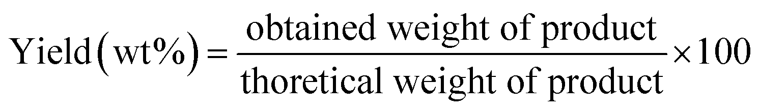
For synthesis of 1-amidoalkyl-2-naphthol, a mixture of benzaldehyde (1.2 mmol), β-naphthol (1.2 mmol), benzamide (1.7 mmol) and 0.1 g of the MOF were mixed in a 100 ml round bottom flask and the subsequent mixture was stirred magnetically under solvent-free condition at 130 °C for the required time. After completion the reaction (confirmed by TLC), the reaction mixture was cooled to room temperature and washed several times with 10 ml hot water with continuous stirring to remove the unreacted starting materials. The product was filtered off and the separated catalyst was washed with ethanol and finally dried in an oven at 120 °C for reuse. Amidoalkyl-2-naphthol was collected from the filtrate and then recrystallized from ethanol.45,51 The product was characterized by its melting point (235–237 °C) and FT-IR. The % yield of 1-amidoalkyl-2-naphthol can be calculated easily from the following equation:
3 Results and discussion
3.1. X-ray diffraction analysis
The low and high-angle XRD patterns of pure MCM-41 were illustrated in Fig. 1a. At 2θ = 2.4, 4.0 and 4.6°, respectively, the three characteristic peaks of the ordered hexagonal mesoporous structure were observed, while at 2θ = 10–60° there is abroad hump due to formation of an amorphous phase.47 Fig. 1b shows that the MOF/MCM-41 composites still maintains the mesoporous structure of MCM-41 by the appearance of the peak (100) at 2.4°. The XRD patterns of Cu-MOF/MCM-41, Ag-MOF/MCM-41, Cu–Ag MOF/MCM-41 composites and Cu–Ag MOF are presented in Fig. 1c. All the main diffraction peaks of the octahedral Cu-MOF appeared in Cu-MOF/MCM-41 pattern at 2θ = 9.03°, 10.23°, 12.34°, 17.36°, 20.67°, 24.92°, 29.30°, 34.33°, 42.12° which assigned to (220), (222), (400), (440), (442), (731), (751), (951) and (971), respectively. These peaks are in a good agreement with the patterns of Cu-MOF in the literature52,53 indicating the successful preparation of the MOF. The peaks of Ag-MOF/MCM-41 composite appeared at 2θ = 13.27°, 16.74°, 18.93°, 28.51°, 30.88°, 38.11°, 44.37°, 64.46°, 77.35° in a good agreement with the literature.54 The peaks at 2θ = 38.11° (111), 44.37° (200), 64.46° (220) and 77.35° (311) corresponds to a face centered cubic of Ag species nanoparticles which may be produced from the reduction of Ag+ to Ag metal with the aid of DMF as reducing agent.55–58 The bimetallic Cu–Ag MOF/MCM-41 composite combines the characteristic peaks of both Cu-MOF and Ag-MOF with a small shift of the peaks of Cu to lower 2θ values supporting the successful preparation of bimetallic MOF.59,60 Comparing the pattern of Cu–Ag MOF with that of Cu–Ag MOF/MCM-41, the intensities of the main diffraction peaks of Cu and Ag-MOF are decreased meaning that MCM-41 enhances the crystallinity of the MOF/MCM-41 composites.
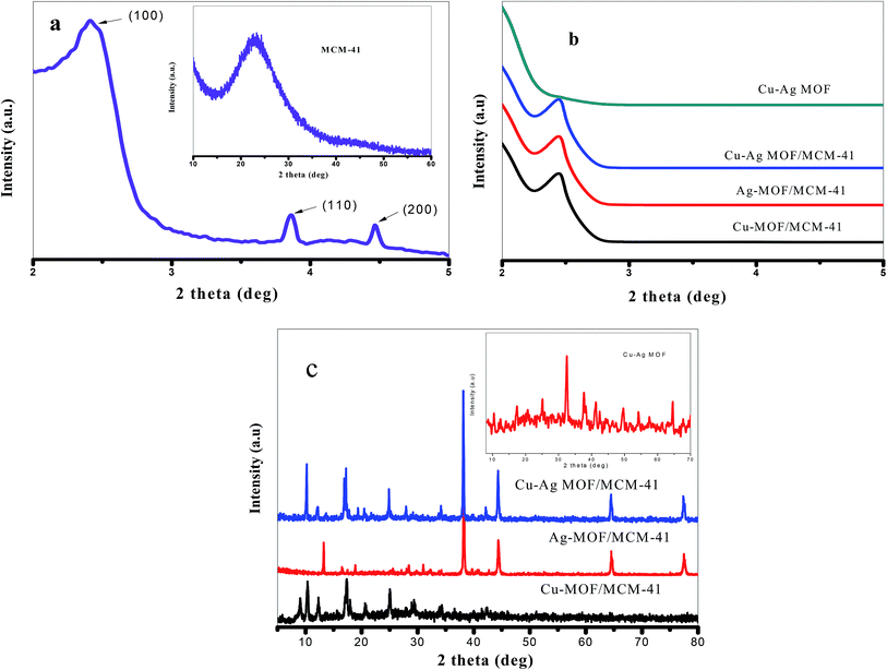 |
| | Fig. 1 (a) Low and high-angle XRD of MCM-41 and (b) low-angle and (c) high-angle XRD for the prepared catalysts. | |
3.2. FT-IR spectroscopy
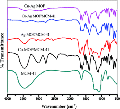
The FT-IR spectra of the prepared MOFs are shown in Fig. 2. The spectra of pure MCM-41, Cu-MOF/MCM-41, Ag-MOF/MCM-41, Cu–Ag-MOF/MCM-41 and Cu–Ag MOF exhibit clear absorption spectra corresponding to metal–organic framework structure with a little shift in the wavelengths. The FT-IR spectra in the region 700–1200 cm−1 attributed to the fingerprint of terephthalate compounds in which the absorption over 900 cm−1 is related to the bending aromatic C–H (in plane) and the absorption lower than 900 cm−1 is related to the bending aromatic C–H (out plane) of terephthalic acid linker.55,61,62 The stretching band of C–H groups related to linker is appeared at 2999 cm−163 Also, the peaks at 1621 and 1393 cm−1 are related to the carboxylate ligands. The vibration absorption spectra of the C–O group of free carboxylic acids are observed at 1666 and 1470 cm−164 and the peaks at 575, 621 and 674 cm−1 belongs to the stretching vibrations of the Cu–O.65,66 Also, the broad band appeared at 3456 cm−1 in the FT-IR spectra of Cu-MOF/MCM-41 and Ag-MOF/MCM-41 composites attributes to the vibration of coordinated water molecules.67 MOF/MCM-41 composites exhibit bands of MCM-41 at 803, 959 and 1252 cm−1 with a little shift which is good evidence on maintaining the mesoporous structure of MCM-41.47,68 The disappearance of the broad spectra at 3456 cm−1 in the FT-IR spectra of Cu–Ag MOF/MCM-41 composite and Cu–Ag MOF indicates the removal of the water during the formation of bimetallic MOF.
 |
| | Fig. 2 FTIR spectra of the prepared catalysts. | |
3.3. SEM and EDX
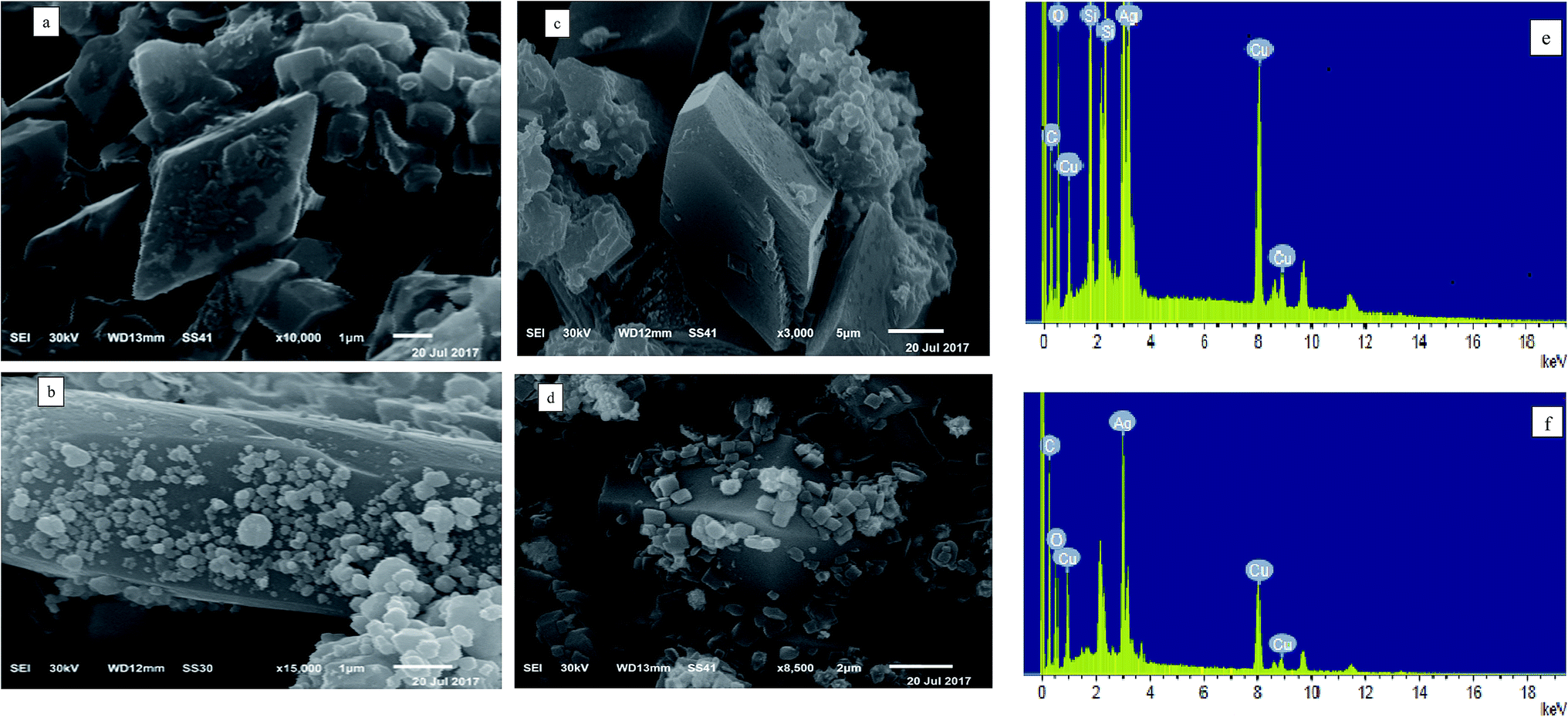
The SEM and EDX images of Cu-MOF/MCM-41, Ag-MOF/MCM-41, Cu–Ag MOF/MCM-41 composites and Cu–Ag MOF are presented in Fig. 3. The SEM image of Fig. 3a displays the dispersion of octahedral Cu structure on the surface of MCM-41,64,69 while Fig. 3b shows the dispersed irregular spherical Ag particles with different sizes the surface of MCM-41.70 There is a significant difference in the surface morphology of the two bimetallic MOFs, Cu–Ag MOF/MCM-41 composite and Cu–Ag MOF (Fig. 3(c and d), respectively). The images show that the agglomeration of irregular small Ag particles increased after the addition of MCM-41 which resulted in the appearance of more dispersed blocks on its surface. This explains the significant effect of the incorporation of MCM-41 during the formation of MOF and the high dispersion of the Cu–Ag MOF inside and outside the pores of MCM-41.66,68,71 The EDX spectra in Fig. 3(e and f) reveal the contribution of C, O, Cu, Ag, and Si elements in the Cu–Ag MOF/MCM-41 composite structure while C, O, Cu and Ag elements in the Cu–Ag MOF structure.
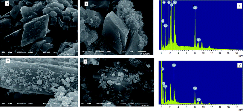 |
| | Fig. 3 SEM images of ((a) Cu-MOF/MCM-41, (b) Ag-MOF/MCM-41, (c) Cu–Ag MOF/MCM-41 and (d) Cu–Ag MOF) and EDX analysis of ((e) Cu-MOF/MCM-41 and (f) Cu–Ag MOF). | |
3.4. X-ray photoelectron spectroscopic (XPS)
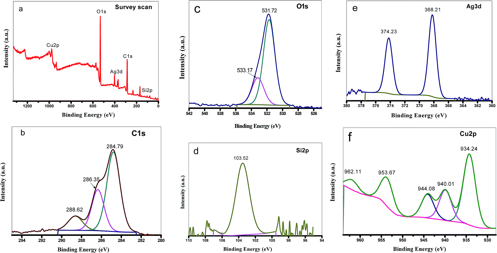
To determine the chemical composition of Cu–Ag MOF/MCM-41 composite and the chemical state of its elements, XPS was performed (Fig. 4.). As shown in the XPS survey scan (Fig. 4a.), the Cu–Ag MOF/MCM-41 composite contains Cu, Ag, C, O and Si elements which consisted with the EDX results. The C 1s XPS spectrum (Fig. 4b.) reveals three peaks at 284.79, 286.35 and 288.62 eV which are attributed to C–C & C–H & C![[double bond, length as m-dash]](https://www.rsc.org/images/entities/char_e001.gif) C, C–O and O–C–O groups, respectively.72 O 1s emission spectrum (Fig. 4c.) has two main peaks at 531.72 eV (characteristic of metal–oxygen bonds) and 533.17 eV (characteristic of the O–H groups).73 The Si 2p emission spectrum shows only one peak at 103.52 eV (Fig. 4d.). Ag 3d XPS spectrum (Fig. 4e.) exhibits two main peaks at 368.21 eV (Ag 3d3/2) and 374.23 eV (Ag 3d5/2) which are ascribed to metallic Ag. The 6 eV spin-energy separation between the two peaks of Ag 3d confirmed on the presence of Ag0 in the Cu–Ag MOF/MCM-41 composite54,74 that may be produced from the reduction of Ag+ to Ag metal with the aid of DMF as reducing agent as explained in XRD results. The high resolution spectrum of Cu 2p exhibits five peaks at 934.24, 940.01, 944.08, 953.67 and 962.11 eV (Fig. 4f.). The peaks at 934.24 and 953.67 eV were assigned to Cu 2p3/2 and Cu 2p1/2 of Cu–O. The presence of overlapping satellite peaks at 940.01 and 944.08 eV for Cu 2p3/2 and at 962.11 eV for Cu 2p1/2 indicated the presence of CuO (Cu2+) or Cu2O (Cu1+) species in the composite.75,76
C, C–O and O–C–O groups, respectively.72 O 1s emission spectrum (Fig. 4c.) has two main peaks at 531.72 eV (characteristic of metal–oxygen bonds) and 533.17 eV (characteristic of the O–H groups).73 The Si 2p emission spectrum shows only one peak at 103.52 eV (Fig. 4d.). Ag 3d XPS spectrum (Fig. 4e.) exhibits two main peaks at 368.21 eV (Ag 3d3/2) and 374.23 eV (Ag 3d5/2) which are ascribed to metallic Ag. The 6 eV spin-energy separation between the two peaks of Ag 3d confirmed on the presence of Ag0 in the Cu–Ag MOF/MCM-41 composite54,74 that may be produced from the reduction of Ag+ to Ag metal with the aid of DMF as reducing agent as explained in XRD results. The high resolution spectrum of Cu 2p exhibits five peaks at 934.24, 940.01, 944.08, 953.67 and 962.11 eV (Fig. 4f.). The peaks at 934.24 and 953.67 eV were assigned to Cu 2p3/2 and Cu 2p1/2 of Cu–O. The presence of overlapping satellite peaks at 940.01 and 944.08 eV for Cu 2p3/2 and at 962.11 eV for Cu 2p1/2 indicated the presence of CuO (Cu2+) or Cu2O (Cu1+) species in the composite.75,76
 |
| | Fig. 4 XPS spectra of Cu–Ag MOF/MCM-41 composite: (a) the survey scan, (b) C 1s, (c) O 1s, (d) Si 2p, (e) Ag 3d and (f) Cu 2p. | |
3.5. Surface area measurements
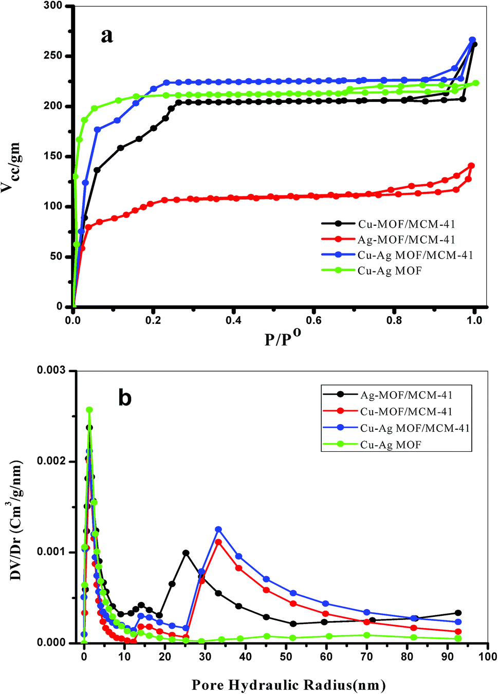
The porosity of the prepared materials was characterized by N2 adsorption–desorption isotherms at −196 °C. As shown in Fig. 5a., the Cu, Ag and Cu–Ag MOF/MCM-41 composites exhibit type IV isotherm typical of mesoporous materials with H3 hysteresis loop. A linear increase in N2 adsorption at low relative pressure is observed due to the formation of monolayer followed by the capillary condensation of N2 inside the mesopores.63 The Cu–Ag MOF exhibits type I isotherm indicating the microporous nature of the MOF with H3 hysteresis loop indicating the presence of cylindrical pores.71 The derived porosity parameters, surface area and pore volume, were calculated and listed in Table 1. The surface area of MCM-41 was 1389.2 m2 g−1 as mentioned previously in our literature,47 while the pore volume was 3.63 cm3 g−1. Ag-MOF/MCM-41, Cu-MOF/MCM-41 and Cu–Ag MOF/MCM-41 composites have a BET surface area 296.4, 545.2 and 594.8 m2 g−1, respectively which are lower than that of MCM-41. This can be explained by the partial blocking of the pores of MCM-41 through the dispersion of the MOF particles inside and/or outside them although the maintaining of the mesostructure which is very important for catalysis applications.77,78 This was confirmed also by the decrease in the pore volume. The increase in the surface area and pore volume of the bimetallic Cu–Ag MOF compared with each monometallic MOF is observed that may be resulted from the creation of new micropores arises from two metals Cu and Ag in the bimetallic MOF. These values increases when the bimetallic MOF composited with MCM-41 as a result of presence of both meso and micropores. The pore size distribution curves (Fig. 5b.) for all samples exhibit a narrow micropores peak characteristic of the MOF centered at 1.27 nm. The MOF/MCM-41 composites show also a mesoporous nature with two maxima from 10 to 50 nm. Cu-MOF/MCM-41 and Cu–Ag MOF/MCM-41 composites reveals two peak centered at 14 and 33 nm while Ag-MOF/MCM-41 composite reveal two peaks centered at 14 and 25 nm.
 |
| | Fig. 5 (a) N2 adsorption–desorption isotherms and (b) pore size distribution of the prepared composites. | |
Table 1 Surface and acidic properties of the prepared catalysts
| Catalyst |
SBET (m2 g−1) |
Vt (cm3 g−1) |
Ei (mV) |
No. of acid sites/g × 10−20 |
| Cu-MOF/MCM-41 |
545.2 |
0.32 |
225.1 |
1.64 |
| Ag-MOF/MCM-41 |
296.4 |
0.18 |
128.2 |
1.34 |
| Cu–Ag MOF/MCM-41 |
594.8 |
0.37 |
369.9 |
2.46 |
| Cu–Ag MOF |
551.3 |
0.34 |
276.2 |
2.03 |
3.6. Surface acidity
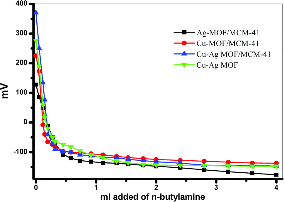
3.6.1. Nonaqueous potentiometric titration. To determine the strength and the total number of acid sites on the MOFs surface, we used the potentiometric titration for the prepared MOFs with n-butyl amine79 and the curves are shown in Fig. 6. The acid strength of these sites can be determined from the value of the initial electrode potential (Ei) and classified as follows: (i) when Ei is increased than 100 mV, the sites are classified as very strong acid sites,(ii) when Ei is between 0 and 100 mV, the sites are strong sites, (iii) when Ei is between −100 and 0 mV, the sites are weak sites, and (iv) when Ei is less than −100 mV, the sites are very weak sites.80 From Fig. 6 and Table 1, the values of the initial electrode potential indicate that all the prepared MOFs have very strong acid sites and Cu–Ag MOF/MCM-41 composite has the highest number of total acid sites and the highest Ei value.
 |
| | Fig. 6 Potentiometric titration curves of n-butyl amine in acetonitrile for the prepared catalysts. | |
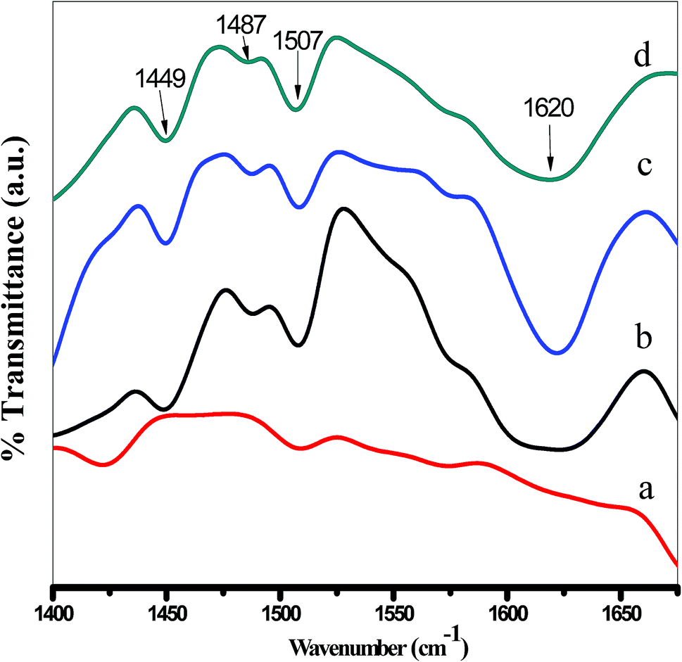
3.6.2. FTIR spectra of chemisorbed pyridine. The infrared spectra of adsorbed pyridine on the surface of the MOFs were used to determine the type of acid sites whether Brønsted or Lewis as shown in Fig. 7. The spectra show two bands at 1507 and 1421 cm−1 on Ag-MOF/MCM-41 composite and four bands in the samples Cu-MOF/MCM-41, Cu–Ag MOF/MCM-41 composites and Cu–Ag MOF at 1449, 1487, 1507 and 1620 cm−1 which are assigned to the adsorbed pyridine on Lewis acidic sites.81–83
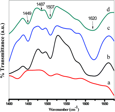 |
| | Fig. 7 FTIR spectra of adsorbed pyridine on (a) Ag-MOF/MCM-41, (b) Cu-MOF/MCM-41, (c) Cu–Ag MOF/MCM-41 and (d) Cu–Ag MOF. | |
3.7. Catalytic activity (synthesis of 1-amidoalkyl-2-naphthol)
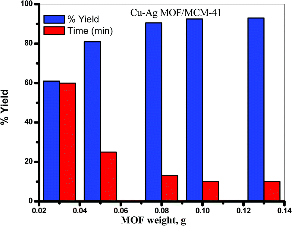
The catalytic activity was examined by synthesis of pharmaceutically important 1-amidoalkyl-2-naphthol. Firstly, to optimize various reaction parameters, we performed some trials for the synthesis of 1-amidoalkyl-2-naphthol as a model reaction on MOF catalyst; the conditions of a MOF amount and the reactants molar ratio under solvent free condition at 130 °C are examined.
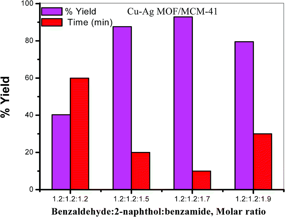
3.7.2. Effect of the molar ratio of the reactants. The reaction was performed on 0.1 g Cu–Ag MOF/MCM-41 composite under solvent free condition at 130 °C by using different molar ratio of the reactants. The best yield was obtained with a molar ratio 1.2![[thin space (1/6-em)]](https://www.rsc.org/images/entities/char_2009.gif) :1.2:1.7 of benzaldehyde:β-naphthol:benzamide after 10 min as shown in Table 2 and Fig. 9.
:1.2:1.7 of benzaldehyde:β-naphthol:benzamide after 10 min as shown in Table 2 and Fig. 9.
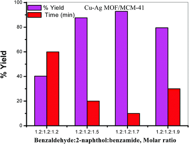 |
| | Fig. 9 Effect of the molar ratio of reactants on the synthesis of 1-amidoalkyl-2-naphthol. | |
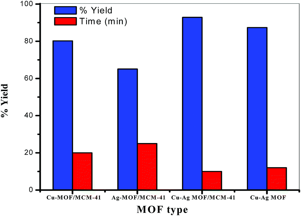
3.7.3. Effect of MOF type. The synthesis of 1-amidoalkyl-2-naphthol reaction was carried out using 0.1 g of different MOFs (Cu-MOF/MCM-41, Ag-MOF/MCM-41, Cu–Ag MOF/MCM-41 composites and Cu–Ag MOF) using 1.2:1.2:1.7 benzaldehyde:β-naphthol:benzamide molar ratio under solvent free condition at 130 °C. The catalytic activity of the prepared bimetallic catalysts is increased compared with that of the monometallic catalyst which could be attributed to the presence of two different metals Cu and Ag and/or changing the active sites dispersion on the MOF surface in the bimetallic catalyst.5,12,84–86 The results in Fig. 10 and Table 2 illustrate that Cu–Ag MOF/MCM-41 composite is the best catalyst with respect to reaction times (10 min) and yields (92.86%) of the products. The enhancement in the catalytic activity of this composite may be due to the following four factors: (i) the various active sites on the MOF surface with higher strength and acidity especially Lewis acid sites, (ii) the high surface area (iii) the presence of both meso and micropores and (iv) the presence of both Cu and Ag metals.
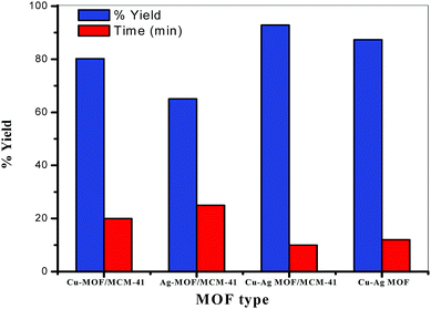 |
| | Fig. 10 Effect of the MOF type on the synthesis of 1-amidoalkyl-2-naphthol. | |
In comparison with other literatures; 1-amido alkyl-2-naphthol was obtained under solvent free conditions with a yield of 88% after 20 min using graphene oxide as a catalyst at 120 °C, 86% after 75 min using Ba3(PO4)2 catalyst at 100 °C and 90% after 25 min using sulfonated polynaphthalene at 80 °C.45,87,88
A possible mechanism for the synthesis of 1-amidoalkyl-2-naphthol was suggested in Scheme 1, based on the literature.89 The reaction of benzaldehyde with β-naphthol in the presence of MOF catalyst produces ortho-quinone methides (o-QMs) which reacted with benzamide via conjugated addition on the α,β-unsaturated carbonyl group to yield 1-amidoalkyl-2-naphthol. It was found that using benzaldehyde as aromatic aldehyde is better than aliphatic aldehyde which gave low yield in previous reports,90,91 this can be attributed to an o-QMs intermediate produced from aliphatic aldehydes is less stable than that with aromatic aldehyde.
 |
| | Scheme 1 A possible mechanism for the synthesis of 1-amidoalkyl-2-naphthol. | |
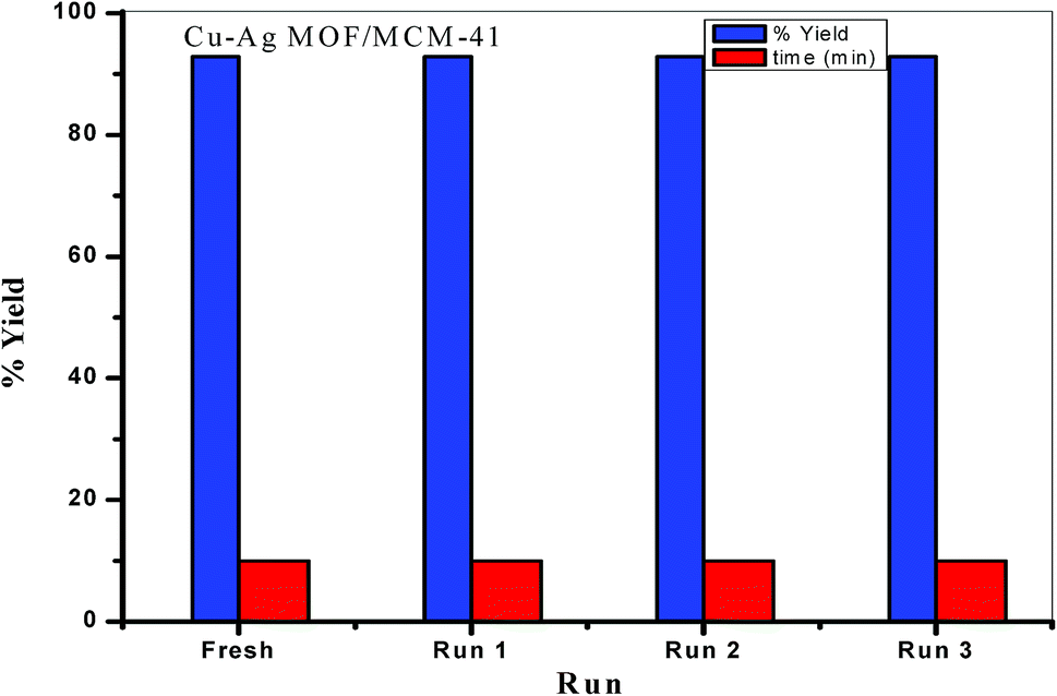
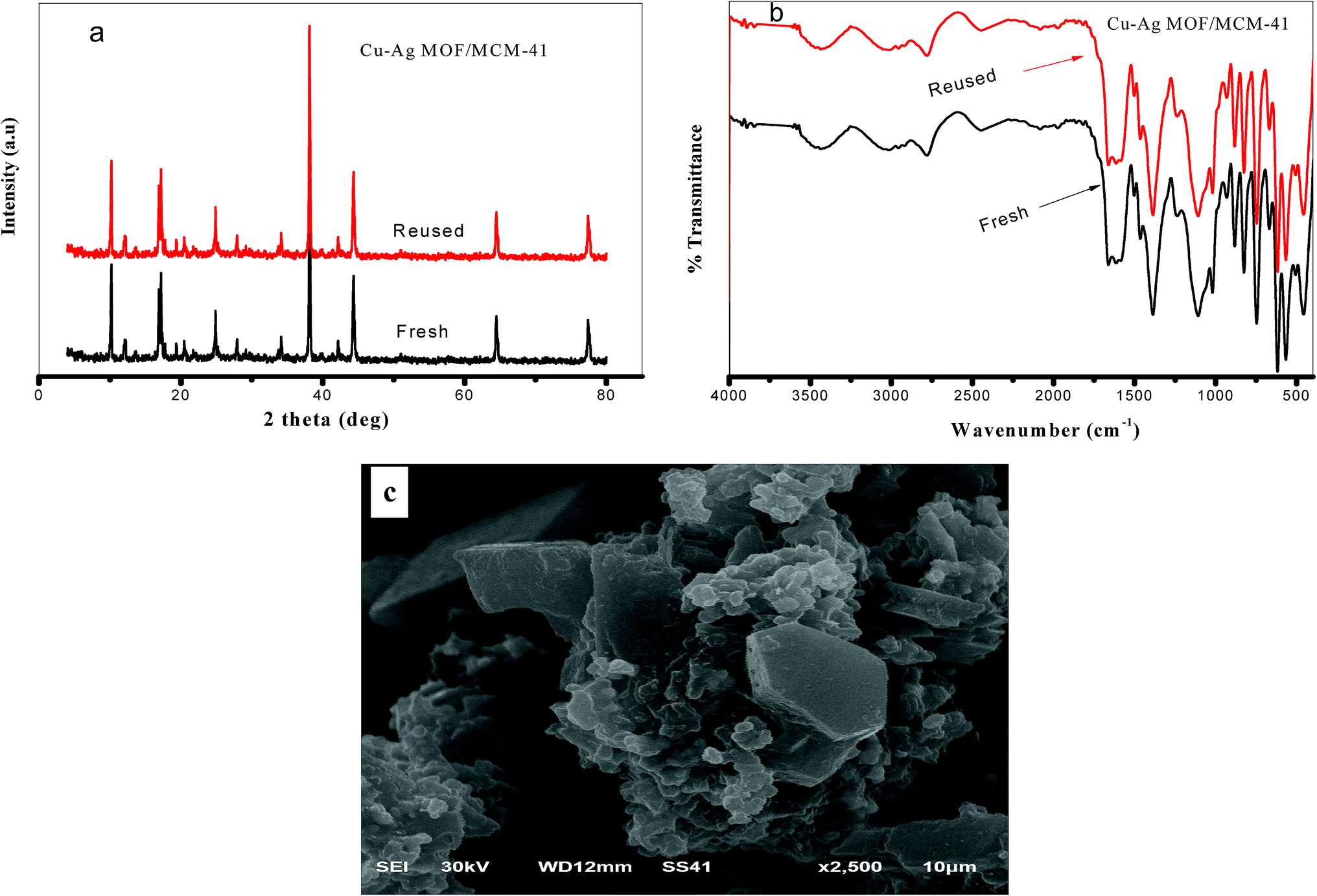
3.7.4. Reusability of the catalyst. The reusability is one of the most important characteristics of any catalyst. The recycling experiment was carried out with benzaldehyde, β-naphthol and benzamide under the same conditions as described above for the Cu–Ag MOF/MCM-41 composite catalyst. To maintain constant catalyst weight (0.1 g) during reusability experiments, we performed each experiment four times using the Cu–Ag MOF/MCM-41 composite in the same time and the second, third and fourth recycles are carried out by the same catalyst and constant weights. We found that Cu–Ag MOF/MCM-41 composite can be used four times without any reduction in the catalytic activity (Fig. 11.). The FTIR, XRD and SEM analysis were determined for the fresh and reused Cu–Ag MOF/MCM-41 composite as shown in Fig. 12.
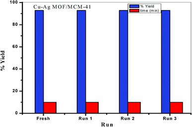 |
| | Fig. 11 Reuse of the Cu–Ag MOF/MCM-41 composite. | |
 |
| | Fig. 12 (a) XRD, (b) FTIR and (c) SEM analysis of reused Cu–Ag MOF/MCM-41 composite after catalytic reaction. | |
4 Conclusion
We found that MCM-41 enhanced the crystallinity and the catalytic activity of the prepared MOFs. The bimetallic Cu–Ag MOF/MCM-41 composite in comparing with other MOFs has the highest Lewis acidity and gave the best yield (92.86%) of 1-amidoalkyl-2-naphthol in 10 min. The enhancement in the catalytic activity of this bimetallic MOF/MCM-41 composite could be attributed to its well acidity, its high surface area, the presence of both meso and micropores and the presence of both Cu and Ag metals.
Conflicts of interest
There are no conflicts to declare.
References
- J. Zhao, Y. Wang, J. Zhou, P. Qi, S. Li, K. Zhang, X. Feng, B. Wang and C. Hu, J. Mater. Chem. A, 2016, 4, 7174–7177 RSC.
- S.-J. Lee, K. C. Kim, T.-U. Yoon, M.-B. Kim and Y.-S. Bae, Microporous Mesoporous Mater., 2016, 236, 284–291 CrossRef CAS.
- Q.-L. Zhu and Q. Xu, Chem. Soc. Rev., 2014, 43, 5468–5512 RSC.
- J.-R. Li, R. J. Kuppler and H.-C. Zhou, Chem. Soc. Rev., 2009, 38, 1477–1504 RSC.
- X. Yang and Q. Xu, Cryst. Growth Des., 2017, 17(4), 1450–1455 CrossRef CAS.
- J. An, S. J. Geib and N. L. Rosi, J. Am. Chem. Soc., 2009, 131, 8376–8377 CrossRef CAS PubMed.
- M. D. Allendorf, C. A. Bauer, R. K. Bhakta and R. J. Houk, Chem. Soc. Rev., 2009, 38, 1330–1352 RSC.
- X. Lian and B. Yan, RSC Adv., 2016, 6, 11570–11576 RSC.
- J. Xiao, Y. Wu, M. Li, B. Y. Liu, X. C. Huang and D. Li, Chem.–Eur. J., 2013, 19, 1891–1895 CrossRef CAS PubMed.
- Q. Yuan, D. Zhang, L. V. Haandel, F. Ye, T. Xue, E. J. M Hensen and Y. Guan, J. Mol. Catal. A: Chem., 2015, 406, 58–64 CrossRef CAS.
- D. Zhang, Y. Guan, E. J. M. Hensen, T. Xue and Y. Wang, Catal. Sci. Technol., 2014, 4, 795–802 RSC.
- B. Xia, C. Liu, H. Wu, W. Luo and G. Cheng, Int. J. Hydrogen Energy, 2015, 40, 16391–16397 CrossRef CAS.
- P. Puthiaraj, A. Ramu and K. Pitchumani, Asian J. Org. Chem., 2014, 3, 784–791 CrossRef CAS.
- M. Y. Masoomi and A. Morsali, RSC Adv., 2013, 3, 19191–19218 RSC.
- X. Cheng, A. Zhang, K. Hou, M. Liu, Y. Wang, C. Song, G. Zhang and X. Guo, Dalton Trans., 2013, 42, 13698–13705 RSC.
- Z.-Q. Li, L.-G. Qiu, T. Xu, Y. Wu, W. Wang, Z.-Y. Wu and X. Jiang, Mater. Lett., 2009, 63, 78–80 CrossRef CAS.
- J. Klinowski, F. A. A. Paz, P. Silva and J. Rocha, Dalton Trans., 2011, 40, 321–330 RSC.
- W. J. Rieter, K. M. L. Taylor, H. An, W. Lin and W. Lin, J. Am. Chem. Soc., 2006, 128, 9024–9025 CrossRef CAS PubMed.
- A. Nikseresht, A. Daniyali, M. A. Mohammadi, A. Afzalinia and A. Mirzaie, Ultrason. Sonochem., 2017, 37, 203–207 CrossRef CAS PubMed.
- I.-H. Choi, Y. Kim, D. N. Lee and S. Huh, Polyhedron, 2016, 105, 96–103 CrossRef CAS.
- T. N. Lieu, K. D. Nguyen, D. T. Le, T. Truong and N. T. S. Phan, Catal. Sci. Technol., 2016, 6, 5916–5926 RSC.
- X.-Q. Wu, G.-X. Wen, Y.-P. Wu, W.-W. Dong, J. Zhao and D.-S. Li, J. Solid State Chem., 2016, 42, 243–247 CrossRef.
- G. H. Dang, H. Q. Lam, A. T. Nguyen, D. T. Le, T. Truong and N. T. S. Phan, J. Catal., 2016, 337, 167–176 CrossRef CAS.
- T. D. Le, K. D. Nguyen, V. T. Nguyen, T. Truong and N. T. S. Phan, J. Catal., 2016, 333, 94–101 CrossRef CAS.
- P. Li, S. Regati, R. J. Butcher, H. D. Arman, Z. Chen, S. Xiang, B. Chen and C.-G. Zhao, Tetrahedron Lett., 2011, 52, 6220–6222 CrossRef CAS PubMed.
- G. Chen, S. Wu, H. Liu, H. Jiang and Y. Li, Green Chem., 2013, 15, 230–235 RSC.
- L. T. L. Nguyen, T. T. Nguyen, K. D. Nguyen and N. T. S. Phan, Appl. Catal., A, 2012, 425/426, 44–52 CrossRef.
- M. Ghorbanloo, V. Safarifard and A. Morsali, New J. Chem., 2017, 41, 3957–3965 RSC.
- S. Li and F. Huo, Nanoscale, 2015, 7, 7482–7501 RSC.
- L. Li, X. L. Liu, H. Y. Geng, B. Hu, G. W. Song and Z. S. Xu, J. Mater. Chem. A, 2013, 1, 10292–10299 RSC.
- T. Han, Y. Xiao, M. Tong, H. Huang, D. Liu, L. Wang and C. Zhong, Chem. Eng. J., 2015, 275, 134–141 CrossRef CAS.
- T. Wehner, K. Mandel, M. Schneider, G. Sextl and K. Müller-Buschbaum, ACS Appl. Mater. Interfaces, 2016, 8, 5445–5452 CrossRef CAS.
- B. Szczęśniak, J. Choma and M. Jaroniec, Microporous Mesoporous Mater., 2019, 279, 387–394 CrossRef.
- F. Wang, X. Chen, L. Chen, J. Yang and Q. Wang, Mater. Sci. Eng., C, 2019, 96, 41–50 CrossRef CAS PubMed.
- Y. Liu, P. Ghimire and M. Jaroniec, J. Colloid Interface Sci., 2019, 535, 122–132 CrossRef CAS PubMed.
- Y. Han, H. Xu, Y. Su, Z.-l. Xu, K. Wang and W. Wang, J. Catal., 2019, 370, 70–78 CrossRef CAS.
- R. Ameloot, A. Liekens, L. Alaerts, M. Maes, A. Galarneau, B. Coq, G. Desmet, B. F. Sels, J. F. M. Denayer and D. E. De Vos, Eur. J. Inorg. Chem., 2010, 24, 3735–3738 CrossRef.
- M. Florent and T. Bendosz, Microporous Mesoporous Mater., 2015, 204, 8–14 CrossRef CAS.
- L. B. Sun, J. R. Li, W. Lu, Z. Y. Gu, Z. Luo and H. C. Zhou, J. Am. Chem. Soc., 2012, 134(38), 15923–15928 CrossRef CAS.
- S. K. Sharma, K. Sudarshan, D. Sen and P. K. Pujari, J. Solid State Chem., 2019, 279, 10–17 CrossRef.
- N. Cakiryilmaz, H. Arbag, N. Oktar, G. Dogu and T. Dogu, Catal. Today, 2019, 323, 191–199 CrossRef CAS.
- Y. Chi, J. Xue, J. Zhuo, D. Zhang, M. Liu and Q. Yao, Sci. Total Environ., 2018, 633, 1105–1113 CrossRef CAS.
- G. Zhan and H. C. Zeng, Coord. Chem. Rev., 2016, 320–321, 181–192 CrossRef CAS.
- A. Chinnappan, A. H. Jadhav, W.-J. Chung and H. Kim, J. Mol. Liq., 2015, 212, 413–417 CrossRef CAS.
- S. A. Pourmousavi, P. Moghimi, F. Ghorbani and M. Zamani, J. Mol. Struct., 2017, 1144, 87–102 CrossRef CAS.
- M. N-Esfahani, M. Montazerozohori and M. Taei, C. R. Chim., 2016, 19, 986–994 CrossRef.
- A. I. Ahmed, S. E. Samra, S. A. El-Hakam, A. S. Khder, H. Z. El-Shenawy and W. S. Abo El-Yazeed, Appl. Surf. Sci., 2013, 282, 217–225 CrossRef CAS.
- T. Han, C. Li, X. Guo, H. Huang, D. Liu and C. Zhong, Appl. Surf. Sci., 2016, 390, 506–512 CrossRef CAS.
- A. I. Ahmed, S. A. El-Hakam, A. S. Khder and W. S. Abo El-Yazeed, J. Mol. Catal. A: Chem., 2013, 366, 99–108 CrossRef CAS.
- A. I. Ahmed, S. A. El-Hakam, M. A. Abd Elghany and W. S. Abo El-Yazeed, Appl. Catal., A, 2011, 407, 40–48 CrossRef CAS.
- A. Davoodnia, R. Mahjoobin and N. Tavakoli-Hoseini, Chin. J. Catal., 2014, 35, 490–495 CrossRef CAS.
- S. Rostamnia, H. Alamgholiloo and X. Liu, J. Colloid Interface Sci., 2016, 469, 310–317 CrossRef CAS PubMed.
- A. R. Abbasi, M. Karimi and K. Daasbjerg, Ultrason. Sonochem., 2017, 37, 182–191 CrossRef CAS PubMed.
- H. Guo, Y. Zhang, Z. Zheng, H. Lin and Y. Zhang, Talanta, 2017, 170, 146–151 CrossRef CAS PubMed.
- D. K. Yadav, V. Ganesan, F. Marken, R. Gupta and P. K. Sonkar, Electrochim. Acta, 2016, 219, 482–491 CrossRef CAS.
- R. Gupta and V. Ganesan, Sens. Actuators, B, 2015, 219, 139–145 CrossRef CAS.
- P. K. Sonkar and V. Ganesan, J. Solid State Electrochem., 2015, 19, 2107–2115 CrossRef CAS.
- P. K. Rastogi, V. Ganesan and S. A. Krishnamoorthi, J. Mater. Chem. A, 2013, 2, 933–943 RSC.
- J. Yang, C. Zheng, P. Xiong, Y. Li and M. Wei, J. Mater. Chem. A, 2014, 2, 19005–19010 RSC.
- Z. Zhou, L. Mei, C. Ma, F. Xu, J. Xiao, Q. Xia and Z. Li, Chem. Eng. Sci., 2016, 147, 109–117 CrossRef CAS.
- S. R. Thakare and S. M. Ramteke, Catal. Commun., 2017, 102, 21–25 CrossRef CAS.
- N. Iswarya, M. G. Kumar, K. S. Rajan and R. J. B. Balaguru, Asian J. Sci. Res., 2012, 5, 247–254 CrossRef CAS.
- N. E. Tari, A. Tadjarodi, J. Tamnanloo and S. Fatemim, J. CO2 Util., 2016, 14, 126–134 CrossRef CAS.
- S. Mosleh, M. R. Rahimi, M. Ghaedi, K. Dashtian and S. Hajati, RSC Adv., 2016, 6, 17204–17214 RSC.
- J. Zhou, X. Li, L. Yang, S. Yan, M. Wang, D. Cheng, Q. Chen, Y. Dong, P. Liu, W. Cai and C. Zhang, Anal. Chim. Acta, 2015, 899, 57–65 CrossRef CAS.
- Q. Chen, X. Li, X. Min, D. Cheng, J. Zhou, Y. Li, Z. Xie, P. Liu, W. Cai and C. Zhang, J. Electroanal. Chem., 2017, 789, 114–122 CrossRef CAS.
- S. Aryanejad, G. Bagherzade and A. Farrokhi, Inorg. Chem. Commun., 2017, 81, 37–42 CrossRef CAS.
- S. W. Li, R. M. Gao, R. L. Zhang and J. S. Zhao, Fuel, 2016, 184, 18–27 CrossRef CAS.
- J. B. Raoof, S. R. Hosseini, R. Ojani and S. Mandegarzad, Energy, 2015, 90, 1075–1081 CrossRef CAS.
- L. Ai, X. Liu and J. Jiang, J. Alloys Compd., 2015, 625, 164–170 CrossRef CAS.
- S. W. Li, J. R. Li, Q. P. Jin, Z. Yang, R. L. Zhang, R. M. Gao and J. S. Zhao, J. Hazard. Mater., 2017, 337, 208–216 CrossRef CAS PubMed.
- M.-J. Tian, F. Liao, Q.-F. Ke, Y.-J. Guo and Y.-P. Guo, Chem. - Eur. J., 2017, 328, 962–976 CAS.
- D. Chen, C. Chen, W. Shen, H. Quan, S. Chen, S. Xie, X. Luo and L. Guo, Adv. Powder Technol., 2017, 28, 1769–1779 CrossRef CAS.
- J. H. Cui, C. F. Hu, Y. H. Yang, Y. J. Wu, L. F. Yang, Y. L. Wang, Y. L. Liu and Z. Y. Jiang, J. Mater. Chem., 2012, 22, 8121–8126 RSC.
- X. Xiao, S. Peng, C. Wang, D. Cheng, N. Li, Y. Dong, Q. Li, D. Wei, P. Liu, Z. Xie, D. Qu and X. Li, J. Electroanal. Chem., 2019, 841, 94–100 CrossRef CAS.
- T. Aydan, C. Yang, Y. Xu, T. Yuan, M. Zhang, H. Li, X. Liu, X. Su and J. Wang, Inorg. Chem. Commun., 2019, 102, 162–170 CrossRef CAS.
- N. E. Tari, A. Tadjarodi, J. Tamnanloo and S. Fatemi, Microporous Mesoporous Mater., 2016, 231, 154–162 CrossRef CAS.
- J. Ying, Z.-Y. Hu, X.-Y. Yang, H. Wei, Y.-X. Xiao, C. Janiak, S.-C. Mu, G. Tian, M. Pan, Gu. V. Tendeloob and B.-L. Su, Chem. Commun., 2016, 52, 8219–8222 RSC.
- L. R. Pizzo, P. G. Vásquez, C. V. Cáceres and C. V. Blanco, Proceedings of the 17th Symposium Iberoam, Catalysts, 2000, 1, 563 Search PubMed.
- L. R. Pizzio, P. G. Vásquez, C. V. Cáceres and M. N. Blanco, Appl. Catal., A, 2003, 256, 125–139 CrossRef CAS.
- P. Carnitia, A. Gervasinia, F. Bossolab and V. D. Santo, Appl. Catal., B, 2016, 193, 93–102 CrossRef.
- C. R. Reddy, G. Nagendrappa and B. S. Jai Prakash, Catal. Commun., 2007, 8, 241–246 CrossRef CAS.
- M. N. Alaya and M. A. Rabah, J. Alloys Compd., 2013, 575, 285–291 CrossRef CAS.
- W. Yu, Y. P. Hsu and C. S. Tan, Appl. Catal., B, 2016, 196, 185–192 CrossRef CAS.
- Y. Miao, S. Li, L. Gao and G. Xiao, Mol. Catal., 2017, 436, 128–137 CrossRef.
- H. Liu, R. Fang, Z. Li and Y. Li, Chem. Eng. Sci., 2015, 122, 350–359 CrossRef CAS.
- A. Gupta, D. Kour, V. K. Gupta and K. K. Kapoor, Tetrahedron Lett., 2016, 57, 4869–4872 CrossRef CAS.
- H. Taghrir, M. Ghashang and M. N. Biregan, Chin. Chem. Lett., 2016, 27, 119–126 CrossRef CAS.
- S. A. R. Mulla, T. A. Salama, M. Y. Pathan, S. M. Inamdar and S. S. Chavan, Tetrahedron Lett., 2013, 54, 672–675 CrossRef CAS.
- Z. K-Jaberi and H. Fakhraei, Bull. Chem. Soc. Ethiop., 2012, 26, 473–478 Search PubMed.
- A. R. Supale and G. S. Gokavi, J. Chem. Sci., 2010, 122, 189–192 CrossRef CAS.
|
| This journal is © The Royal Society of Chemistry 2019 |
Click here to see how this site uses Cookies. View our privacy policy here. 
 Open Access Article
 This Open Access Article is licensed under a Creative Commons Attribution-Non Commercial 3.0 Unported Licence
 * and
Awad I. Ahmed
* and
Awad I. Ahmed