
 Open Access Article
 This Open Access Article is licensed under a Creative Commons Attribution-Non Commercial 3.0 Unported Licence
Enhancing the permeability and anti-fouling properties of a polyamide thin-film composite reverse osmosis membrane via surface grafting of L-lysine
Tianyu Liu,
Dandan Chen,
Feng Yang,
Jinyao Chen ,
Ya Cao,
Ming Xiang,
Jian Kang and
Ruizhang Xu*
,
Ya Cao,
Ming Xiang,
Jian Kang and
Ruizhang Xu*
State Key Laboratory of Polymer Materials Engineering, Polymer Research Institute of Sichuan University, Chengdu 610065, People's Republic of China. E-mail: xrz@stu.scu.edu.cn; Fax: +86-028-8540 6578; Tel: +86-028-8540 6333
First published on 27th June 2019
Abstract
The application of a reverse osmosis (RO) membrane is greatly restricted on account of a trade-off between water flux and salt rejection, as well as poor anti-fouling properties. In order to improve the surface hydrophilicity of RO membranes, L-lysine (Lys) was grafted onto polyamide selective layers with the premise of maintaining the original surface morphology and thickness, which were verified through scanning electron microscopy and atomic force microscopy analysis. X-ray photoelectron spectroscopic measurements confirmed the occurrence of the reaction. After modification, the RO membranes exhibited notably enhanced hydrophilicity due to a steep decline in their water contact angles. The results of cross-flow filtration tests manifested that the modified membranes showed evident enhancements in water flux and salt rejection. For the optimized samples, the water flux increased by 22.45% compared with the pristine membrane, and the salt rejection rose up to 98.53% from the initial value of 95.44%. After grafting, the RO membranes performed much better in fouling resistance, especially towards protein and cationic foulants. The mechanism of how grafted Lys affected the performance of the RO membranes was analyzed. This research provides a feasible method to optimize the performance of RO membranes.
1. Introduction
With the rapid growth in population, human beings are encountering the enormous dilemma of water shortage. Despite the ample water resources on Earth,1 seawater makes up the greatest proportion, which is a water source that cannot be used directly in either production or in the everyday lives of humans. In view of this situation, seawater desalination has become a popular issue. Developed in the 1960s,2,3 reverse osmosis (RO) has been applied to separate solvent and solute under operating pressure. Later in 1978, Cadott et al. developed a thin-film composite (TFC) technique, which drove the commercialization of the RO technique tremendously.4Nowadays, polyamide (PA) TFC RO membrane has become the industrial standard in THE desalination field due to its outstanding durability, stability, and universality.5,6 However, the main hindrance for the application of PA TFC RO membrane can be ascribed to its poor anti-fouling properties and the trade-off between water flux and salt rejection.7–9 Bacterial and colloidal foulants are prone to adhering on the hydrophobic surface, which dramatically diminishes the membrane's permeability.10,11 Improving the surface hydrophilicity is a common strategy that is applied for preparing membranes with outstanding performance. According to the preferential sorption-capillary flow mechanism proposed by Sourirajan and Yuster,12 a hydrophilic membrane surface is conducive to building hydrogen bonds with solute and constructing an ultrathin hydration layer, contributing to prior sorption of the solute. As verified by numerous studies,13–15 improving the membrane hydrophilicity can lower the foulant affinity and ameliorate fouling issues in the meantime.
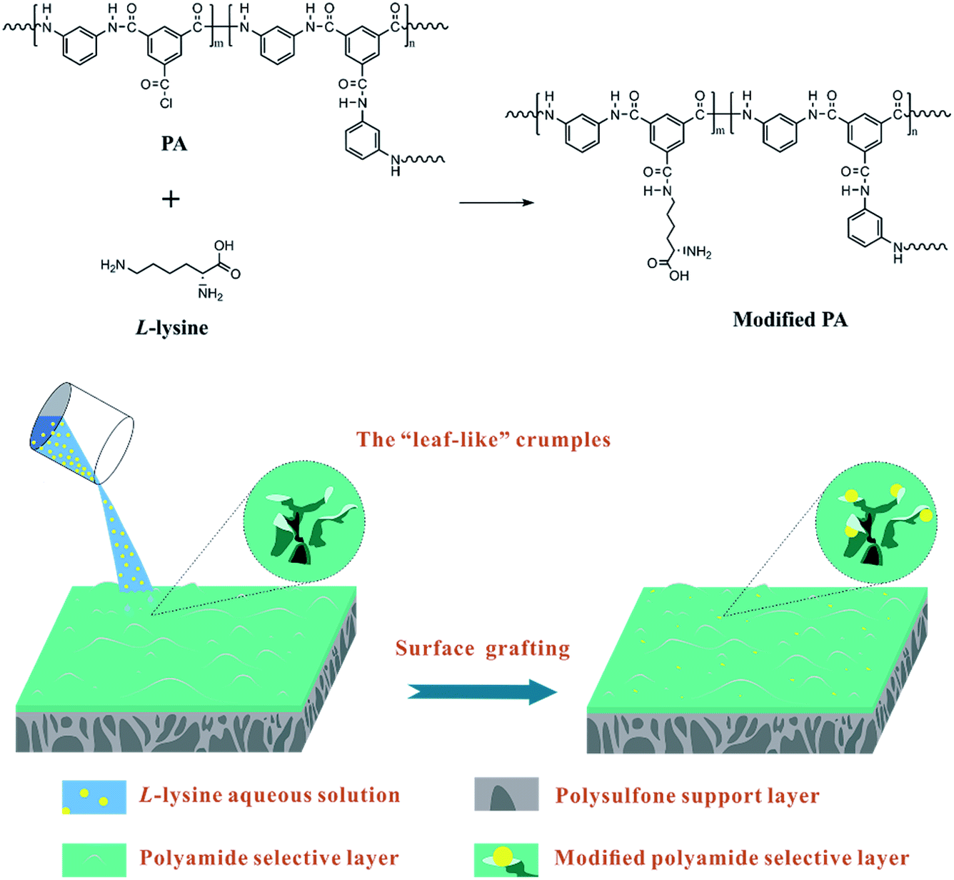
Nevertheless, surface grafting or coating with polymers is generally associated with undesirable aspects. The modifying polymers, for example, polyvinyl alcohol (PVA)16 and polyethylene glycol (PEG) derivatives,17,18 overlay the pristine surface through covalent connection. Although the low anti-fouling issue is mitigated, the aforementioned process could alter the surface structure and thickness of the PA selective layer obviously, which play crucial roles in the membrane performance.19,20 The “ridge-and-valley” structure formed during interfacial polymerization (IP) result in the formation of a rough morphology with an abundant specific surface area. Hence, massive molecular passages reside on the “leaf-like” ridges.21 When the original membrane was covered by a hydrophilic polymer layer, the mass transfer resistance directly increased due to blocked or narrowed pores and the longer travelling distance for both the water molecules and salt ions. For example, Yu et al.22 coated a hydrophilic polymer, sericin, onto commercial membranes as a protective layer. The fabricated membranes exhibited low-fouling behavior together with decreased water permeation. A novel surface modification was exploited to attain low-fouling RO membranes by photopolymerization.23 Inevitably, the water flux of the obtained membranes suffered a certain loss.
Therefore, to ameliorate the poor anti-fouling properties of RO membrane without impairing water permeation, short-chain hydrophilic molecules were chosen to implement surface modification, since the grafting is expected to barely influence the thickness of the selective layers. Amino acids are hydrophilic short-chain molecules whose amine groups are capable of reacting with the residual acyl chlorine groups of nascent PA TFC RO membranes. L-lysine (Lys), a hydrophilic amino acid, was utilized in the surface modification of RO membrane. The choice of Lys was motivated by the following concerns. First, it can react with the acyl chlorine of nascent PA TFC RO membrane at a fast rate,24 thus ensuring a relatively high grafting efficiency. As aqueous monomers, several amino acids were attempted to implement interfacial polymerization with TMC solutions, such as arginine and glutamine. It turned out that the reaction rate of Lys is superior than that of other amino acids, corresponding to a higher grafting efficiency, as the acyl chlorine of PA selective layers would transform into carboxyl quickly in the presence of the aqueous modifying solutions during surface grafting. Second, the amine and carboxyl groups of Lys result in better hydrophilicity of the RO membrane surface to enhance the anti-fouling properties and water permeation. Besides this, the aliphatic Lys is similar to the aromatic m-phenylenediamine (MPD) in terms of chain arrangement and elemental content, so the former can be regarded as a second monomer to further perfect the membrane structure without obviously altering the surface morphology and chemical composition of the RO membrane.25
Hence, different concentrations of Lys solutions were prepared and reacted with the residual acyl chlorine end groups on a pristine TFC membrane surface. The chemical structures, surface morphologies and physicochemical properties of the fabricated membranes were investigated thoroughly to verify the occurrence of the reaction and explore the effects of modification. Cross-flow filtration tests were implemented to evaluate the permeation and fouling resistance of the membranes. A possible model of the grafting of Lys onto the surface of TFC membranes is shown in Scheme 1.
 | ||
| Scheme 1 A possible model of the surface grafting of Lys onto a PA TFC RO membrane surface. | ||
2. Materials and methods
2.1. Materials
Polysulfone (PSf, Mw = 22![[thin space (1/6-em)]](https://www.rsc.org/images/entities/char_2009.gif) 000 g mol−1) was purchased from Solvay (China). N,N-Dimethylformamide (DMF) (analytical purity of 99.5%), 1,3,5-benzenetricarbonyl trichloride (TMC, 98%), m-phenylenediamine (MPD, 99%), n-hexane (anhydrous, 99%), and L-lysine (98%) were purchased from Aladdin (China). Bovine serum albumin (BSA), sodium dodecyl sulfate (SDS) and dodecyltrimethyl ammonium bromide (DTAB), purchased from Aladdin (China), were utilized for evaluating the anti-fouling performance. De-ionized water used in the research was prepared in our own laboratory.
000 g mol−1) was purchased from Solvay (China). N,N-Dimethylformamide (DMF) (analytical purity of 99.5%), 1,3,5-benzenetricarbonyl trichloride (TMC, 98%), m-phenylenediamine (MPD, 99%), n-hexane (anhydrous, 99%), and L-lysine (98%) were purchased from Aladdin (China). Bovine serum albumin (BSA), sodium dodecyl sulfate (SDS) and dodecyltrimethyl ammonium bromide (DTAB), purchased from Aladdin (China), were utilized for evaluating the anti-fouling performance. De-ionized water used in the research was prepared in our own laboratory.
2.2. Preparation and modification of the PA TFC membranes
PSf support layers were prepared using a phase separation method.26 The concentration of the PSf casting solution was 18 wt% in DMF, and the temperature of the non-solvent (distilled water) bath was 25 °C. The prepared PSf support layers were kept in 4 °C de-ionized water before further use.The PA selective layers were prepared on the PSf support layers via interfacial polymerization.27 In brief, the PSf layer was held between a glass plate and Teflon frame. Next, a 2.0 wt% MPD aqueous solution was deposited on the PSf support layer. After 3 min, the MPD aqueous solution was removed and droplets on the PSf layer surface were blown away completely using high pressure nitrogen. Then, a 0.1 wt% TMC n-hexane solution was poured on the membrane surface for 30 seconds. The reaction was ceased by pouring pure n-hexane on the membrane surface to remove unbonded TMC.
After the volatilization of n-hexane, the pristine TFC membranes were immediately soaked with Lys aqueous solutions with various concentrations (1, 3, 5, 7 and 10 wt%, respectively) for 2 min. After removal of the redundant aqueous solution, the modified membranes were washed gently using distilled water for 3 min to ensure the entire removal of unbonded Lys, then kept in 4 °C de-ionized water before testing. These samples were denoted as L-x (x = 0, 1, 3, 5, 7 and 10), in which x corresponds to the concentration of the Lys solution, thus L-0 represents the nascent TFC membrane (without the grafting of Lys).
2.3. Characterization of the PA TFC membranes
The chemical composition and structure of the PA selective layers were determined by attenuated total reflectance Fourier-transform infrared spectroscopy (ATR-FTIR, Nicolet iS 50 FTIR, Thermo Fisher Scientific, USA), in the wavenumber range of 4000–700 cm−1. X-ray photoelectron spectroscopy (XPS, Axis Ultra DLD, Kratos Analytical, UK) was also employed to detect the atomic proportions (C, N and O) of the grafted membrane surface.The surface properties of the membrane samples were examined. Contact angles (CA) were measured via the sessile drop method with a contact angle instrument (K100, KRUSS, Germany) to judge the variation in membrane hydrophilicity before and after the grafting of Lys. A 4 μL water droplet was introduced onto each dried membrane and the CA of the water drop on the PA surface was measured. Five different spots on each sample were chosen to implement repetitive measurements, and the obtained data were averaged as the final results.
An Anton Paar SurPASS Electrokinetic Analyzer (Anton Paar, US) was adopted to measure the zeta potentials of the membrane samples at 25 °C. All tests were conducted in the pH value range of 4.0–10.0. A KCl aqueous solution was used as the background electrolyte.
The morphology of the membrane surface was characterized through scanning electron microscopy (SEM, Inspect F, FEI, USA). Atomic force microscopy (AFM, Asylum Research MFP-3D microscope, Oxford Instruments, UK) was utilized to evaluate the surface roughness of the membranes quantitatively. A 5 μm × 5 μm area was scanned in tapping mode and three different spots on each membrane were chosen to repeat the measurements.
2.4. Membrane permeation performances
The pure water flux (PWF) and salt rejection (R) were both tested with a cross-flow flat membrane filtration experimental instrument (FlowMem0021-HP, FMT, China). A 2000 ppm NaCl aqueous solution served as the feed solution for the purpose of measuring salt rejection. Trials on each membrane were conducted at 25 ± 0.5 °C under a trans-membrane pressure of 16 bar.The PWF of the PA TFC membrane was calculated by employing the following equation:
 | (1) |
The salt rejection (R) was calculated by employing the following equation:
 | (2) |
2.5. Membrane anti-fouling properties
In the anti-fouling tests, BSA (protein foulant), DTAB (positively charged foulant) and SDS (negatively charged foulant) were adopted to evaluate the anti-fouling properties of the membranes. The concentrations of BSA, DTAB, and SDS were 1000, 50 and 2000 ppm, respectively, and the trials were carried out with the aforementioned cross-flow membrane filtration under the same conditions as those referred to in Section 2.4. The flux decline ratio (DRt) was chosen to indicate the membrane's capacity of fouling resistance quantitatively, which is calculated using the following equation:
 | (3) |
To determine the membranes' recovery ability, the flux recovery ratio (FRR) was measured according to the following equation:
 | (4) |
3. Results and discussion
3.1. ATR-FTIR analysis
The chemical composition of the membrane samples was investigated by ATR-FTIR, and the IR spectra are presented in Fig. 1. In detail, the peaks at 1661 and 1540 cm−1 correspond to C![[double bond, length as m-dash]](https://www.rsc.org/images/entities/char_e001.gif) O (amide I) and N–H (amide II) stretching,28 illustrating the occurrence of interfacial polymerization. The remarkable absorptions at 1587 and 1325 cm−1 are the two characteristic bands for the PSf support layer.29 Due to the constant penetration depth that IR radiation possesses, if the thickness of the membrane samples underwent notable changes after grafting, the spectral curves would show obvious differences. However, all of the spectra possess similar patterns, reflecting that the grafting was conducted on the mono-molecular level. The existence of Lys is scarcely reflected in the spectra. Apart from grafting at the mono-molecule level as a primary reason, the chain structure and elemental content of MPD resemble those of Lys,24 which may partly account for the undetectable difference between each spectrum.
O (amide I) and N–H (amide II) stretching,28 illustrating the occurrence of interfacial polymerization. The remarkable absorptions at 1587 and 1325 cm−1 are the two characteristic bands for the PSf support layer.29 Due to the constant penetration depth that IR radiation possesses, if the thickness of the membrane samples underwent notable changes after grafting, the spectral curves would show obvious differences. However, all of the spectra possess similar patterns, reflecting that the grafting was conducted on the mono-molecular level. The existence of Lys is scarcely reflected in the spectra. Apart from grafting at the mono-molecule level as a primary reason, the chain structure and elemental content of MPD resemble those of Lys,24 which may partly account for the undetectable difference between each spectrum.
 | ||
| Fig. 1 ATR-FTIR spectra of the PA selective layers with different grafting concentrations. | ||
3.2. XPS analysis
To prove the occurrence of the modifying reaction and determine the grafting efficiency, XPS analysis was carried out to analyze the elemental content. From Fig. 2, the spectra of all of the samples reveal three characteristic peaks (C, N and O, respectively) with invisible distinction. Theoretically, the atomic proportions of N and O in Lys are higher than those of PA, while C in Lys is in a relatively lower proportion in contrast to PA; thus, with a higher concentration of Lys aqueous solution, the proportions of N and O are supposed to rise accordingly, and the opposite is true in the case of C.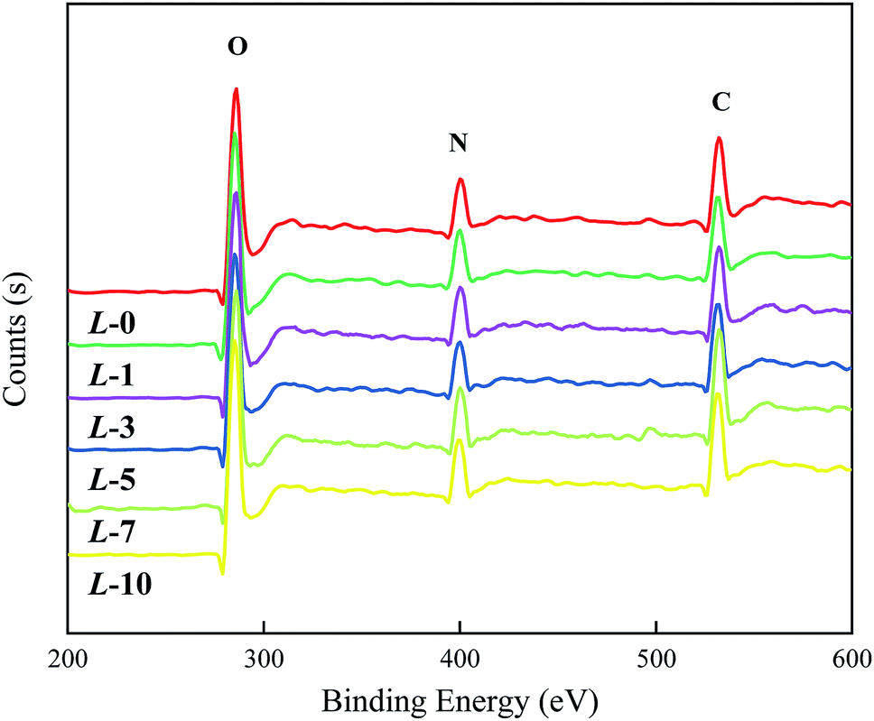 | ||
| Fig. 2 XPS spectra of the PA selective layers grafted with different Lys concentrations. | ||
According to the data in Table 1, the variation in the atomic proportions in the table is coincident with the rule above, which implies an increasing grafting amount along with the increased concentrations of Lys solution. However, quantitative analysis on Lys coverage has not been conducted due to the complexity of the “ridge-and-valley” features on the PA selective layer and the similarity in Lys and MPD in terms of chemical composition.
| Membrane sample | Atomic proportion (%) | ||
|---|---|---|---|
| C | N | O | |
| L-0 | 76.01 | 11.89 | 12.10 |
| L-1 | 75.77 | 12.19 | 12.05 |
| L-3 | 75.68 | 12.11 | 12.21 |
| L-5 | 75.24 | 11.86 | 12.90 |
| L-7 | 74.75 | 12.13 | 13.12 |
| L-10 | 74.42 | 12.66 | 12.92 |
3.3. Contact angle
Surface hydrophilicity is of crucial importance to membrane behavior in practice, which can be characterized by the value of the contact angle. From Fig. 3, a dramatic decline in contact angles occurs as the concentration of Lys increases, from 72° for the nascent membrane to 49.4°, 36.6°, 30.1°, 28.9° and 25.8°, corresponding to L-1, L-3, L-5, L-7, and L-10, respectively. This apparent downtrend indicates that Lys has been anchored on the membranes successfully by chemical bonding. Meanwhile, the membrane hydrophilicity was significantly enhanced when the concentration of Lys was lower than 3%; and for the samples L-5 to L-10, the less pronounced trend indicates that the grafting reaction is tending towards saturation. Even so, the grafting of Lys deeply improved the surface hydrophilicity in comparison with other modifiers reported in other research. For example, Hu et al.30 reduced the water contact angle of a commercial RO membrane to 40.0° by covalently attaching PVA; and Chen et al.25 only attained an optimum hydrophilic RO membrane with 46.9° by grafting small molecules. The hydrophilic groups of grafted Lys are expected to facilitate water adsorption and resist foulant affinity, thus rendering the modified membranes with better performance. | ||
| Fig. 3 The variation in water contact angles for samples processed with Lys solutions of different concentrations. | ||
3.4. Surface charge
Surface streaming potential was used to characterize the surface charge of the PA selective layer in the pH range of 4.0 to 10.0. Normally, the TFC membrane surface has a negatively charged surface due to the existence of carboxyl groups. As illustrated in Fig. 4, after introducing Lys, the membrane surface has less negative charge. | ||
| Fig. 4 Zeta potentials of membrane surfaces before and after the grafting of Lys. | ||
Theoretically, in the reaction process, the grafting of each Lys monomer would consume an acyl chlorine end group while endowing the membrane surface with a carboxyl and amino group. The separate amino group of Lys with a positive charge makes a contribution to an electroneutral membrane, which probably reduces the adhesion of positively charged foulants.
3.5. Surface morphology
SEM and AFM analysis were employed to figure out whether the grafting of Lys influences the surface morphologies of the membranes. As illustrated in Fig. 5, all of the membranes retained common “ridge-and-valley” features. The “leaf-like” crumples, also known as ridges,31 are dispersed evenly and densely on the top surface, on which massive tunnels exist for solvent permeation. Compared to these ridges and valleys with dimensions of tens or hundreds of nanometers,32 the anchored Lys are almost invisible due to their relatively tiny bulk, let alone the deficient grafting degree relying on the unreacted acyl-chlorine terminated group. Coincident with our hypothesis above, the participation of Lys barely impacts on the microscopic morphology of the RO membranes.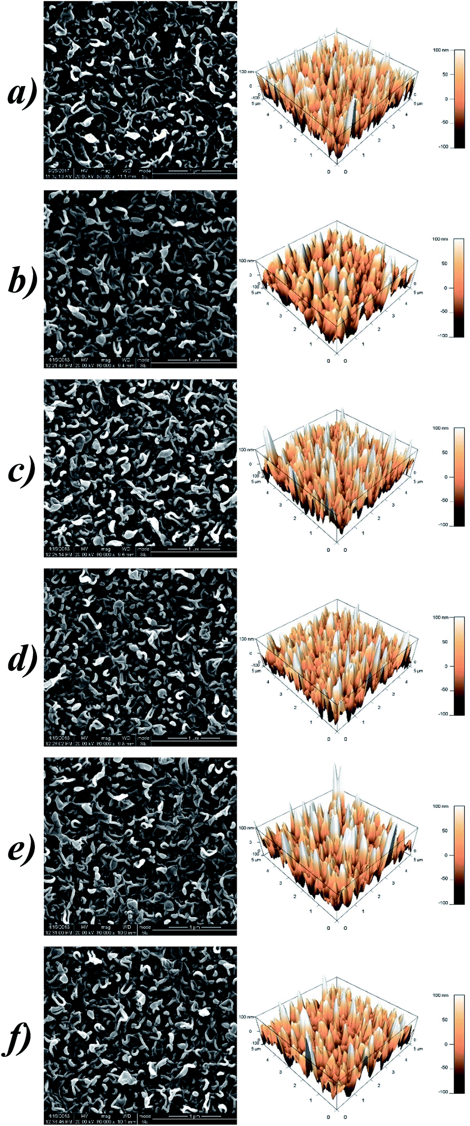 | ||
| Fig. 5 SEM and AFM images of (a) L-0; (b) L-1; (c) L-3; (d) L-5; (e) L-7; and (f) L-10. | ||
The AFM images manifest the thickness and roughness of the PA selective layers quantitatively. The parameters of the roughness are denoted as Rp-v (maximum peak-to-valley distance), Ravg (average roughness) and Rrms (root mean square), and the detailed data are listed in Table 2. The fluctuating values indicate that there are no patterns between the membrane roughness and Lys concentrations, which is similar to the aforementioned research by Chen et al.33 Besides, surface modification with this small molecule hardly affects the thickness of the resulting membranes, therefore less additional osmotic resistance is incorporated for molecular transport. While modification with macromolecules such as PVA normally forms a diverse plane overlaying the top membrane, which generally leads to an undesirable decline in the water permeation.34
| Sample | Maximum peak-to-valley distance, Rp-v (nm) | Surface roughness (nm) | Surface area, S (μm2) | |
|---|---|---|---|---|
| Average, Ravg | Root mean square, Rrms | |||
| L-0 | 372.10 | 40.49 | 49.82 | 32.4 |
| L-1 | 299.40 | 36.23 | 45.35 | 28.7 |
| L-3 | 365.37 | 39.85 | 50.20 | 32.6 |
| L-5 | 354.64 | 36.25 | 45.94 | 31.8 |
| L-7 | 424.01 | 42.11 | 53.83 | 31.1 |
| L-10 | 388.59 | 37.75 | 48.03 | 30.0 |
3.6. Permeability
Fig. 6 demonstrates the sample performances, including the water permeability and salt rejection. The uptrend in the two curves manifests that the grafting has a favorable impact on both the PWF and salt rejection of the RO membranes. The behavior of the water permeation experiences a rapid ascent from L-0 to L-3, reflected by the incremental values from 53.32 to 65.30 L m−2 h−1. Despite a slight reduction in the subsequent samples, all of the modified membranes are superior to the pure TFC membrane in terms of water permeation. Besides this, an enhancement in salt rejection was also attained simultaneously, which presents a positive correlation to the Lys concentration. In detail, the maximum of the desalting coefficient reaches up to 98.53% for L-10, apparently higher than the 95.44% of the pure TFC membrane.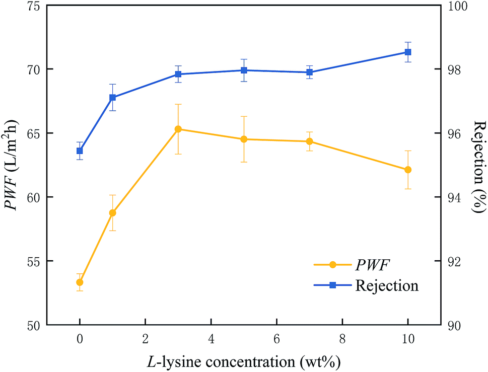 | ||
| Fig. 6 PWF and salt rejection of the membrane samples in 2000 ppm NaCl aqueous solution (25 °C, 1.6 MPa). | ||
Commonly, the introduction of hydrophilic materials onto a PA selective layer would be conducive to increased salt rejection and lower water permeation. However, the well-recognized trade-off seems not to apply in this study. The points below presumably account for this:
(1) Grafting of Lys dramatically ameliorates the hydrophilicity of the RO membrane which facilitates the formation of a hydration layer12 spread on it. In one respect, this water layer promotes the prior sorption of water molecules and increases the membrane water permeability. In the meantime, it could isolate the bulk solution with higher salt concentration, thus alleviating the concentration polarization effect.35
(2) According to the FTIR and AFM analysis, the modified membranes have approximately equal thickness and surface morphology to those of the pristine sample. Hence, the grafting of Lys barely results in the extra transfer resistance generally associated with an additional layer after surface modification.
(3) During the grafting process, Lys could diffuse into the adjacent pores and shrink the passage radius and the anchored Lys located near to the defective area might be conducive to repairing defects.36 These effects result in an incremental obstacle for molecular transport, which may be responsible for the subsequent decline in water permeation and the continuous rise in salt rejection.
3.7. Anti-fouling properties
An investigation on the fouling resistance of the samples (L-0, L-5, L-10) was conducted using BSA, DTAB and SDS as model foulants, which are types of protein, and positively and negatively charged foulants, respectively.34 Here, the time-dependent normalized water flux is defined as the flux ratio of a fouled membrane to the corresponding intact membrane. The detailed data are listed in Table 3.| L-0 | L-5 | L-10 | ||||
|---|---|---|---|---|---|---|
| DRt (%) | FRR (%) | DRt (%) | FRR (%) | DRt (%) | FRR (%) | |
| BSA | 29.6 ± 0.0 | 79.2 ± 0.1 | 15.8 ± 0.1 | 98.2 ± 0.0 | 16.6 ± 0.1 | 97.2 ± 0.2 |
| DTAB | 53.5 ± 0.1 | 72.9 ± 0.4 | 40.5 ± 0.3 | 97.1 ± 0.0 | 30.6 ± 0.7 | 98.6 ± 0.0 |
| SDS | 16.5 ± 0.1 | 89.1 ± 0.1 | 17.4 ± 0.1 | 96.8 ± 0.2 | 20.0 ± 0.0 | 98.4 ± 0.1 |
Graphically in Fig. 7, all three series of curves undergo an apparent downtrend along with the increase in filtration time. When encountering BSA and DTAB solutions (Fig. 6(a) and (b)), the modified membranes (L-5 and L-10) exhibit lower DRt values and higher FRR values compared with sample L-0, illustrating that the introduction of Lys enhances the membrane fouling resistance to these two types of foulants and increases the recovery capacity. It is well-known that membrane surface properties are key factors in fouling issues, especially hydrophilicity, surface charge and roughness. According to the results in the previous sections, a highly hydrophilic (see Section 3.3) membrane with less negative charge (see Section 3.4) was obtained without altering the surface roughness and morphology (see Section 3.5) after the grafting of Lys. Hence, the first two are believed to dominate the anti-fouling manners. A hydrophilic surface generates an ultrathin hydration layer above the modified membrane, which weakens the attachment and adsorption of foulants on it.37–39 Moreover, a modified membrane surface has less negative charge, resulting in a decrease in the inter-attraction between the membranes and positively charged species such as DTAB.
 | ||
| Fig. 7 Anti-fouling tests on membrane samples (L-0, L-5, L-10) with (a) BSA solution, (b) DTAB solution, and (c) SDS solution. | ||
As shown in Fig. 7(c), the curves shows an opposite variation due to the decreased electrostatic repulsion between negatively charged SDS and the modified membrane surface. Despite an inferior fouling resistance against anion foulants, the modified membranes still retain outstanding recovery behavior, which presumably results from their more hydrophilic surface.
4. Conclusions
In this study, Lys was introduced onto the surface of a PA TFC RO membrane via a mild one-step modification. It was proven that Lys was bonded covalently on the PA layer, according to XPS analysis. The variation in the water contact angle and zeta potential ensured the enhanced hydrophilicity and electric neutrality of the modified membrane surfaces. The surface patterns and thicknesses of the modified membranes maintained their original morphology before grafting, which was confirmed by SEM and AFM analysis. Importantly, the modified membranes showed remarkable enhancement in terms of permeability: the water flux of L-3 reached a maximum of 65.30 L m−2 h−1, 22.45% higher than the 53.32 L m−2 h−1 of the original membrane; and the salt rejection kept ascending up to a peak value of 98.53%, from an initial value of 95.44%. Simultaneously, after grafting Lys, the membranes exhibited favorable enhanced fouling resistance, coupled with better recovery capacity after fouling.Conflicts of interest
There are no conflicts to declare.Acknowledgements
Sincere appreciation is extended to the National Natural Science Foundation of China (NSFC 51503134, 51421061, 51721091) and the State Key Laboratory of Polymer Materials Engineering (Grant No. SKLPME 2017-3-02). Owing to their fund support, we can implement our research successfully. The authors would like to thank Lingzhu Yu (National Engineering Research Center for Biomaterials, Sichuan University) for help with the AFM characterization.References
- L. Henthorne and B. Boysen, Desalination, 2015, 356, 129–139 CrossRef CAS.
- N. Thomas, M. O. Mavukkandy, S. Loutatidou and H. A. Arafat, Sep. Purif. Technol., 2017, 189, 108–127 CrossRef CAS.
- H. F. Ridgway, J. Orbell and S. Gray, J. Membr. Sci., 2017, 524, 436–448 CrossRef CAS.
- J. E. Cadott, R. J. Petersen, R. E. Larson and E. E. Erickson, Desalination, 1980, 32, 25–31 CrossRef.
- G. R. Xu, J. N. Wang and C. J. Li, Desalination, 2013, 328, 83–100 CrossRef CAS.
- W. Yan, W. Zhi, J. Wu, Z. Song, J. Wang and S. Wang, J. Membr. Sci., 2016, 498, 227–241 CrossRef CAS.
- S. Jiang, Y. Li and B. P. Ladewig, Sci. Total Environ., 2017, 595, 567 CrossRef CAS PubMed.
- S. R. Suwarno, X. Chen, T. H. Chong, D. Mcdougald, Y. Cohen, S. A. Rice and A. G. Fane, J. Membr. Sci., 2014, 467, 116–125 CrossRef CAS.
- V. Kochkodan and N. Hilal, Desalination, 2015, 356, 187–207 CrossRef CAS.
- S. Y. Kwak, S. H. Kim and S. S. Kim, Environ. Sci. Technol., 2001, 35, 2388–2394 CrossRef CAS PubMed.
- L. Zhao and W. S. W. Ho, J. Membr. Sci., 2014, 455, 44–54 CrossRef CAS.
- M. A. Mazid, Sep. Purif. Technol., 1984, 19, 357–373 CAS.
- D. Nikolaeva, C. Langner, A. Ghanem, M. A. Rehim, B. Voit and J. Meier-Haack, J. Membr. Sci., 2015, 476, 264–276 CrossRef CAS.
- J. Wu, W. Zhi, W. Yan, W. Yao, J. Wang and S. Wang, J. Membr. Sci., 2015, 496, 58–69 CrossRef CAS.
- N. Lei, J. Meng, X. Li and Y. Zhang, J. Membr. Sci., 2014, 451, 205–215 CrossRef.
- Q. Zhang, C. Zhang, J. Xu, N. Yan, S. Li and S. Zhang, Desalination, 2016, 379, 42–52 CrossRef CAS.
- A. Sarkar, P. I. Carver, T. Zhang, A. Merrington, K. J. Bruza, J. L. Rousseau, S. E. Keinath and P. R. Dvornic, J. Membr. Sci., 2010, 349, 421–428 CrossRef CAS.
- B. T. Mcverry, M. C. Y. Wong, K. L. Marsh, J. A. T. Temple, M. J. Catalina, E. M. V. Hoek and R. B. Kaner, Macromol. Rapid Commun., 2014, 35, 1528–1533 CrossRef CAS PubMed.
- G. Joung-Eun, L. Seunghye, C. M. Stafford, L. Jong Suk, C. Wansuk, K. Bo-Young, B. Kyung-Youl, E. P. Chan, C. Jun Young and B. Joona, Adv. Mater., 2013, 25, 4778–4782 CrossRef PubMed.
- L. Yi, L. Sha and K. Zhang, J. Membr. Sci., 2017, 537, 42–53 CrossRef.
- Y. Hao, X. Miao, X. Jian, G. Pan, Z. Yang, Y. Shi, G. Min and Y. Liu, J. Membr. Sci., 2015, 475, 504–510 CrossRef.
- S. Yu, G. Yao, B. Dong, H. Zhu, X. Peng, L. Jia, M. Liu and C. Gao, Sep. Purif. Technol., 2013, 118, 285–293 CrossRef CAS.
- Y. Baek, B. D. Freeman, A. L. Zydney and J. Yoon, Ind. Eng. Chem. Res., 2017, 56(19), 5756–5760 CrossRef CAS.
- R. Xu, X. Guan, J. Wang, J. Chen, Y. Feng, K. Jian and X. Ming, RSC Adv., 2018, 8, 25236–25247 RSC.
- L. Y. Chen, L. P. Wu, H. L. Zhang, Y. B. Gao and J. G. Gai, J. Appl. Polym. Sci., 2017, 135, 45891 CrossRef.
- K. Scott, Handbook of Industrial Membranes, 1995 Search PubMed.
- W. Xie, G. M. Geise, B. D. Freeman, H. S. Lee, G. Byun and J. E. Mcgrath, J. Membr. Sci., 2012, 403–404, 152–161 CrossRef CAS.
- G. D. Kang, C. J. Gao, W. D. Chen, X. M. Jie, Y. M. Cao and Q. Yuan, J. Membr. Sci., 2007, 300, 165–171 CrossRef CAS.
- V. Freger, J. Gilron and S. Belfer, J. Membr. Sci., 2002, 209, 283–292 CrossRef CAS.
- Y. Hu, K. Lu, F. Yan, Y. Shi, P. Yu, S. Yu, S. Li and C. Gao, J. Membr. Sci., 2016, 501, 209–219 CrossRef CAS.
- H. Shen, S. Wang, H. Xu, Y. Zhou and C. Gao, J. Membr. Sci., 2018, 565, 145–156 CrossRef CAS.
- F. Viatcheslav, Environ. Sci. Technol., 2004, 38, 3168–3175 CrossRef.
- L. Y. Chen, L. P. Wu, H. L. Zhang, Y. B. Gao and J. G. Gai, J. Appl. Polym. Sci., 2017, 135, 45891 CrossRef.
- M. Liu, Q. Chen, L. Wang, S. Yu and C. Gao, Desalination, 2015, 367, 11–20 CrossRef CAS.
- J. Kucera, Water Quality Guidelines, 2010 Search PubMed.
- Q. Shi, Y. Su, W. Chen, J. Peng, L. Nie, Z. Lei and Z. Jiang, J. Membr. Sci., 2011, 366, 398–404 CrossRef CAS.
- Q. Cheng, Y. Zheng, S. Yu, H. Zhu, X. Peng, L. Jia, J. Liu, M. Liu and C. Gao, J. Membr. Sci., 2013, 447, 236–245 CrossRef CAS.
- M. He, K. Gao, L. Zhou, Z. Jiao, M. Wu, J. Cao, X. You, Z. Cai, Y. Su and Z. Jiang, Acta Biomater., 2016, 40, 142–152 CrossRef CAS PubMed.
- M. Ginic-Markovic, T. G. Barclay, K. T. Constantopoulos, E. Markovic, S. R. Clarke and J. G. Matisons, Desalination, 2015, 369, 37–45 CrossRef CAS.
| This journal is © The Royal Society of Chemistry 2019 |