DOI:
10.1039/C9RA02587A
(Paper)
RSC Adv., 2019,
9, 22327-22335
Deactivation kinetics of individual C6–C9 aromatics' generation from methanol over Zn and P co-modified HZSM-5
Received
6th April 2019
, Accepted 29th June 2019
First published on 18th July 2019
Abstract
A deactivation kinetic model has been determined for the methanol to aromatic process over a HZSM-5 zeolite catalyst (SiO2/Al2O3 = 30) modified by 1.0 wt% ZnO and 2.0 wt% P, in which the generation rates of C6–C9 aromatics are treated individually while olefins and paraffins are lumped as intermediate and byproduct, respectively. The time-dependent catalytic activity is described by a deactivation coefficient related to the concentration of both methanol and products. The established kinetic model is able to predict the product distribution along with on-stream time under various conditions and is identified to be valid by a model significance test. The effect of operating conditions on catalyst behavior was also investigated: deactivation rate increases dramatically with methanol partial pressure and temperature; higher feed methanol content leads to less aromatics and more paraffin; increasing temperature reduces paraffin generation and results in higher aromatic yield, especially benzene and toluene.
1. Introduction
Aromatic hydrocarbons, especially benzene, toluene and xylene (BTX), are fundamental raw materials in industry that can be used to produce various downstream products. Traditionally, BTX are mainly produced from naphtha reforming and thermal cracking of crude oil. However, due to the expanding market and periodic oil crisis, alternative routes to increase the production of BTX have become a hot topic nowadays.
Methanol to hydrocarbon (MTH) processes are a series of reactions that converts coal, natural gas and biomass into petrochemicals via syngas as intermediates, which can be divided into methanol to olefin (MTO), methanol to propylene (MTP) and methanol to aromatic (MTA) depending on their different target products.1 Among them, MTA process is a promising technology to produce BTX from non-petroleum resources. Zeolites are the main catalysts used to convert methanol into hydrocarbons, and ZSM-5 is the most popular one for the production of gasoline-range components due to its medium pore size, over which methanol is first converted into olefins and then aromatics are generated by oligomerization, cyclization and dehydrogenation of olefins, together with paraffin as the main byproduct from hydrogen transfer reaction.2–4 Chang and Silvestri5 reported that the yield of aromatics is about 41% when methanol and olefins are almost completely converted at 371 °C, but paraffin yield is as high as 51.2%. In order to suppress the formation of paraffin, ZSM-5 catalyst is usually modified by loading metals like Zn,6–9 Ga10–12 and Ag.13–15 Among them, Zn is the most popular metal employed by MTA process. Such modification leads to more Lewis acid (ZnOH+) at the expense of the silanol hydroxyl and proton acid sites, and thus the catalyst is more effective to convert the intermediate olefins into aromatics by dehydrogenation, thereby generating hydrogen as byproduct rather than paraffin.16
With high aromatic yield being achieved over metal-modified HZSM-5, catalyst deactivation also becomes very fast in MTA process because the large aromatic molecular is facile to cause coke formation in the micropores and further block the active sites.8,17–19 To run such a process in industrial scale, fluidized-bed reactor is the most appropriate apparatus for reaction as the catalyst can be regenerated continuously.20 Kinetic model is an essential tool for mathematic simulation of fluidized-bed reactor, which gets insight into process design, optimization and scale-up with less cost and higher efficiency than experiment. However, while plenty efforts have been devoted to the catalyst modification, few studies focus on the kinetic study of MTA process.
Many kinetic models4,21–25 of methanol conversion over HZSM-5 have been published so far based on different catalysts, feed conditions and mechanism. According to the method and model complexity, they can be mainly categorized into two types: (1) lumping kinetics that treat components with similar reaction behavior as one species and assume reaction routes according to the macroscopic product distribution;26,27 (2) single-event microkinetics that derive the kinetic equations from the chemical reactions between individual molecules.28,29 In our previous work, we proposed a detailed kinetic model for the co-reaction of methanol and olefins over HZM-5, in which each olefin, aromatic and paraffin generation and interconversion are simulated individually. A good agreement has been achieved under various feed conditions.
However, these models cannot be directly employed in MTA where the catalyst is modified by metals such as Zn2+ or Ga3+, as the active sites and reaction mechanism as well as aim products are distinct. In order to establish the kinetic model for MTA, several important aspects should be considered. Firstly, the impact of catalyst deactivation on activity and product distribution is indispensable in the kinetic model. Secondly, since dozens of components and hundreds of reactions may possibly occur during methanol converting over zeolites, a simplified but reliable reaction network is required to represent the interested reaction behavior. Thirdly, due to the distinct generation mechanism and application value of C6–C9 aromatics, it is necessary to regress the formation rate of different aromatics individually. As a result, lumped kinetic models is more suitable, but the special application in MTA is scare, and the published ones30 for MTA over modified ZSM-5 usually lumped into one species, which is impossible to predict the yield of individual BTX.
In the present work, a kinetic model for the reaction of MTA over a Zn and P loaded ZSM-5 has been established, in which catalyst deactivation was included in the rate expression. To simplify the reaction network, all olefins and paraffins were regarded as one component, respectively, and C6–C9 aromatics were treated separately as the direct products from olefin through parallel reactions. The pre-exponential factors and activation energies were determined by fitting the experimental kinetic data obtained from a lab-scale fixed-bed reactor. Moreover, the effect of temperature and methanol partial pressure on product distribution and catalyst lifetime were also investigated.
2. Experimental
2.1 Catalyst preparation
ZSM-5 zeolite samples with SiO2/Al2O3 molar ration of 60 in ammonium form was purchased from Tianjin Nankai Catalyst Plant of China. It was converted to its hydrogen form by calcination in static air at 550 °C for 5 h in a muffle furnace with temperature increased at a rate of 5 °C min−1.
Modification of HZSM-5 with Zn2H2P2O8 as the precursor of Zn and P was carried out using incipient wetness impregnation method. After impregnation, the sample was centrifugalized for 10 min, dried at 120 °C for 10 hours and calcined at 550 °C for 5 h. The final loading of ZnO is ca. 1 wt%, and the P final loading is 2.0%. Before being used in kinetic experiments, the catalyst was pressed into tablets, crushed and sieved into a fraction of 200–400 μm.
The physical properties of the prepared catalyst are listed in Table 1. The porous structure was determined by N2 adsorption–desorption at 77 K (Quantachrome autosorb IQ), and the total acidity by Ammonia Temperature Programmed Desorption (NH3-TPD, Micromeritics AutoChem 2920), with the samples saturated with ammonia at 100 °C for 30 min after being outgassed for 30 min at 300 °C and then desorbed with temperature raising from 100 to 700 °C at a rate of 10 °C min−1. The Brønsted/Lewis site ratio at 150 °C was determined by in situ pyridine IR method (PerkinElmer Spectrum), by comparing the intensity of pyridine adsorption bands at 1450 cm−1 and 1545 cm−1, and taking into account the molar extinction coefficients of both adsorption bands (εB = 1.67 cm μmol−1 and εL = 2.22 cm μmol−1).
Table 1 Catalyst properties
| Total acidity, (mmol of NH3) g−1 |
10.01 |
| Brønsted/Lewis site ratio at 350 °C |
0.420 |
| dp, nm |
2.48 |
| SBET, m2 g−1 |
306.3 |
| Vp, cm3 g−1 |
0.19 |
2.2 Catalyst test
The experiments have been carried out under atmospheric pressure in the fixed-bed reactor described in a previous article.21 The U-shaped reactor was made of titanium with an internal diameter of 6 mm and a length of 1 m and was located in a salt bath heated by electric resistance, which provided uniform reaction temperature. Catalyst powder was diluted by quartz sand and loaded in the middle section of reactor. Methanol was vaporized and mixed with N2 in a pre-heater before entering the reactor. To eliminate the effect of external diffusion, the linear velocity was higher than 0.2 m s−1.31 As the main part of the reaction equipment was made of titanium, no methanol decomposition was observed in the blank test.
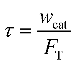
Four temperatures have been investigated between 380 and 480 °C. The partial pressure of methanol was 15, 30 and 50 kPa, with N2 as the dilution gas. The space time was fixed at 11 kg s mol−1, which was calculated by
| |
 | (1) |
where
wcat is the packed catalyst weight, kg;
FT is the total inlet flow rate, mol s
−1.
Product analysis was performed by online GC (gas chromatography) equipped with a flame ionization detector (FID) and a HP-PLOTQ column (30 m × 0.32 mm × 20 μm). Dimethyl ether was regarded as unconverted methanol when discussing conversion and concentration. In each run, the first sample of reactor effluent was taken 10 min after the reactants contacted the catalyst bed, which was marked as TOS = 0. After that, the product mixture was sampled every hour.
3. Experimental result
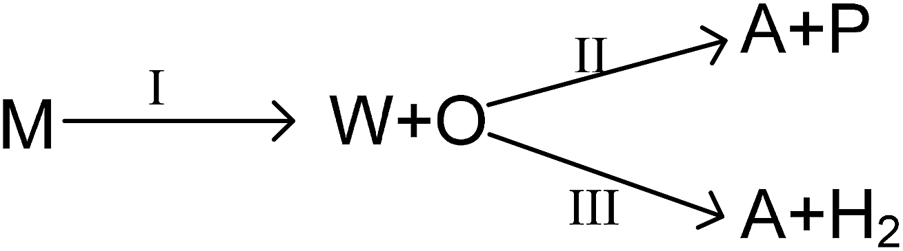
As mentioned above, the main reaction routes in methanol conversion over a Zn and P loaded HZSM-5 can be expressed as follows:
where M, W, O, A and P denote for methanol, water, olefin, aromatic and paraffin. First, methanol is converted into water and olefin over the acidic site (route I), which is a normal MTO process. Then, hydrogen transfer reaction can take place between different olefins to form aromatic and paraffin, mainly over Brønsted acidic site (route II). Meanwhile, olefin can also participate in dehydro-aromatization over L acidic site to form aromatic and hydrogen (route III). Clearly routes II and III are two competitive pathways for olefin consumption and aromatic generation, and the key to obtain high aromatic yield is suppressing the hydrogen transfer process (route II). Olefin, however, is only an intermediate and will finally be converted into paraffin, aromatics or coke as long as the space time is sufficient long.
3.1 Effect of methanol partial pressure
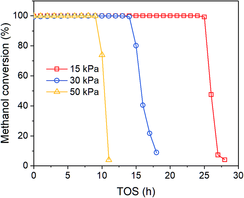
Fig. 1 shows the time-on-stream (TOS) dependent methanol conversion at different inlet methanol partial pressure. Clearly, when increasing reactant concentration, the deactivation proceeds faster, which agrees with other reports. Song et al.32 also reported higher methanol content in the feed leads to more coke formation in the co-reaction of methanol and n-butane over Zn loaded ZSM-5/ZSM-11. Müller et al.33 found methanol concentration is relevant for the deactivation of catalysts in MTO reactions over ZSM-5, as oxygenates generated from methanol can cause fast deactivation. The on-stream time of conversion breakthrough point is 25, 14 and 9 h when feed methanol partial pressure is 15, 30 and 50 kPa, respectively. After that the methanol conversion drops rapidly below 10% within 2–5 h.
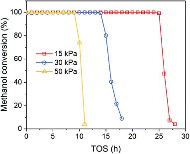 |
| | Fig. 1 Effect of methanol partial pressure on methanol conversion at 450 °C. | |
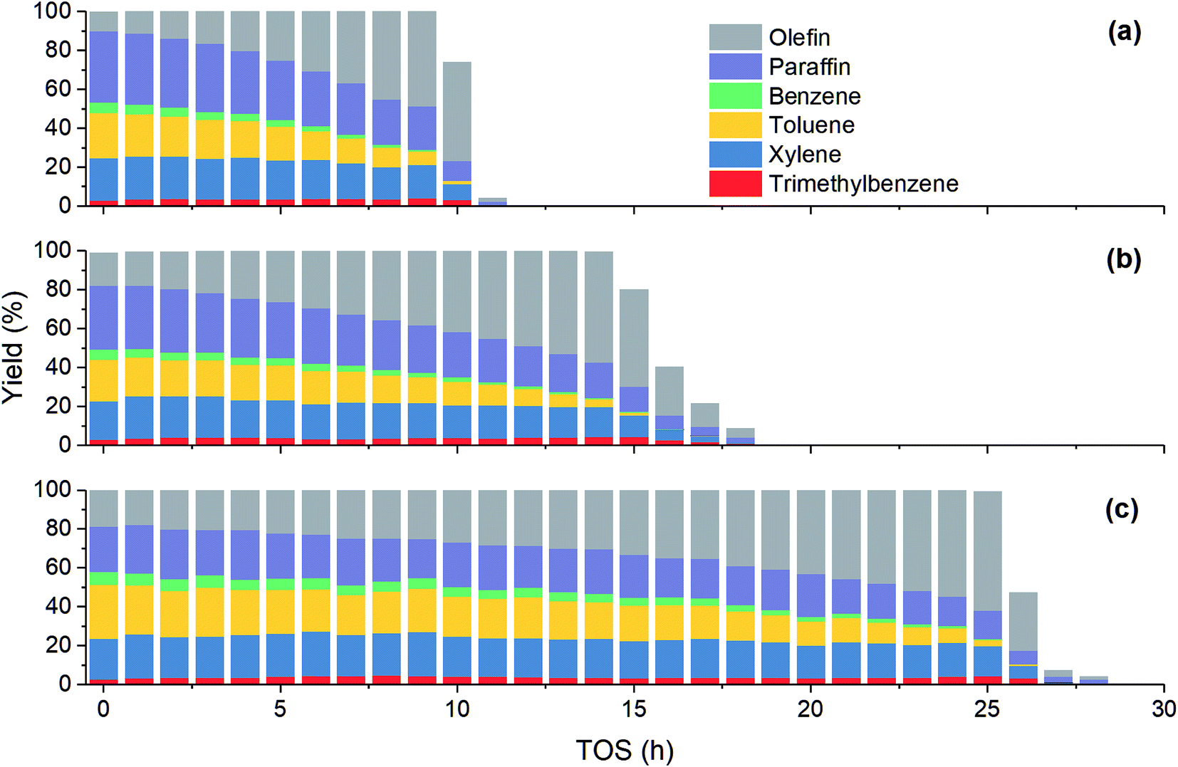
Fig. 2 shows the variation of product yield with TOS at different methanol partial pressure. Under all the three investigated feed conditions, before methanol conversion significantly decreases from 100%, the yield of olefin increases while the yield of other products including paraffin and aromatics decreases. As has been mentioned above, paraffin and aromatics are the terminate products while olefin is the intermediate in MTH process. Therefore, at the early stage of catalyst deactivation, the rest active sites can still completely convert methanol into olefin, but the generation of paraffin and aromatics is impeded due to the less sites available. Unlike other three aromatics, the yield of trimethylbenzene increases slightly with TOS until methanol conversion falls obviously. A possible reason is that such a large molecular can be more easily converted to coke in zeolite, hence its concentration may decrease when olefin concentration becomes low.
 |
| | Fig. 2 Effect of methanol partial pressure on product yield at 450 °C. (a) 15 kPa; (b) 30 kPa; (c) 50 kPa. | |
Table 2 shows the product distribution under different feed conditions. At 450 °C, toluene and xylene are the main aromatic products under various initial methanol concentration, while benzene and trimethylbenzene account for only about 11% and 5% of total aromatics, respectively. When inlet methanol pressure increases from 15 kPa to 50 kPa, the initial yield of olefin decreases because higher reactant concentration results in higher reaction rate. The yield of paraffin also increases, which leads to less aromatic at high methanol concentration. As for individual aromatics, the yield of benzene and toluene with smaller molecular size decreases while that of xylene and C9 aromatics increases slightly, since higher partial pressure makes the oligomerization-cracking equilibrium of olefins shift to heavier intermediate for C8–C9 generation. In a word, to get largest aromatic yield, the feed methanol content should not be too high.
Table 2 Catalytic performance under different reaction conditions
| Exp |
T0 (°C) |
PM,0 (kPa) |
Yield at TOS = 0 h |
Life timea (h) |
| Olefin |
Paraffin |
Aromatic |
Benzene |
Toluene |
Xylene |
C9 |
| Life time is the on-stream time when methanol conversion begins to drop significantly from 100%. |
| 1 |
450 |
15 |
18.94 |
23.18 |
57.88 |
6.79 |
27.64 |
20.91 |
2.54 |
24.00 |
| 2 |
450 |
30 |
13.03 |
32.90 |
54.06 |
6.06 |
24.49 |
20.96 |
2.55 |
14.00 |
| 3 |
450 |
50 |
10.20 |
36.84 |
52.95 |
5.34 |
23.16 |
21.78 |
2.69 |
9.00 |
| 4 |
380 |
30 |
18.31 |
40.87 |
40.82 |
1.70 |
13.38 |
21.51 |
4.23 |
28.00 |
| 5 |
420 |
30 |
12.41 |
38.35 |
49.24 |
3.82 |
20.09 |
22.28 |
3.05 |
21.00 |
| 6 |
480 |
30 |
18.30 |
22.09 |
59.61 |
8.50 |
27.70 |
20.18 |
3.23 |
9.00 |
| 7 |
380 |
50 |
18.39 |
42.31 |
39.30 |
1.52 |
11.96 |
20.79 |
5.03 |
13.00 |
| 8 |
420 |
50 |
11.39 |
41.26 |
47.35 |
3.65 |
18.80 |
21.77 |
3.13 |
12.00 |
| 9 |
480 |
50 |
16.20 |
26.68 |
57.12 |
6.45 |
25.05 |
21.71 |
3.91 |
5.00 |
3.2 Effect of temperature
In order to investigate the effect of temperature on catalyst performance, we also performed the experiment under 380, 420 and 480 °C. As shown in Fig. 3, catalyst life time decreases with reaction temperature, indicating coke is more favored at higher temperature.
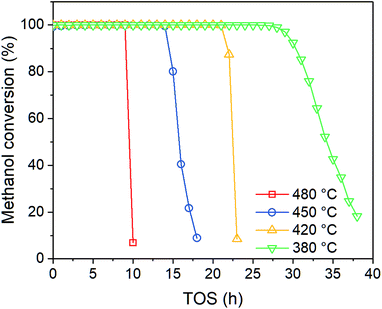 |
| | Fig. 3 Effect of temperature on methanol conversion at PM,0 = 30 kPa. | |
As shown in Fig. 4, the product distribution along with TOS at different temperature changes similarly. As shown in Table 2, at the same methanol feed concentration, when temperature increases from 380 to 420 °C, olefin yield decreases significantly, as the conversion of methanol and the generation of aromatics are accelerated. However, olefin yield increases dramatically from 420 to 480 °C, indicating the total rate of route II and route III is decreased, since the conversion of methanol into olefin over zeolite becomes faster at higher temperature. Paraffin yield decreases continuously with temperature from 380 to 480 °C, meaning the rate of route II is decreased. Huang et al.4 studied the byproduct formation over HZSM-5 and found that the rate of hydrogen transfer decreases with temperature, which was explained by the weaker adsorption of olefins at higher temperature. However, the yield of aromatics always increases with temperature, meaning temperature has positive effect on the rate of route III. For individual aromatics, higher temperature mainly favors the yield of benzene and toluene as their molecular size is smaller, but it decreases the yield of trimethylbenzene with larger size. The yield of xylene with medium size changes very little with temperature.
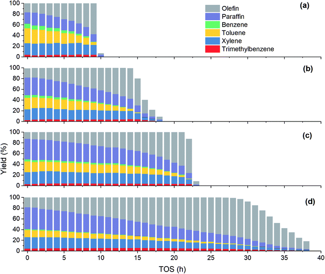 |
| | Fig. 4 Effect of temperature on product yield at PM,0 = 30 kPa. (a) T = 480 °C; (b) T = 450 °C; (c) T = 420 °C; (d) T = 380 °C. | |
4. Kinetic model establishment
4.1 Description of the kinetic model
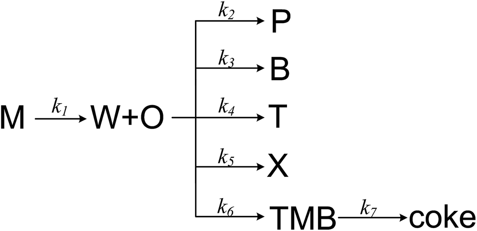
MTA process over Zn and P loaded ZSM-5 involves numerical components and reactions, and it is complex to establish a detail kinetic model by taking every possible step into account. A more realizable solution is to lump components that are similar or irrelevant, which has been widely used in the kinetic modelling of MTO and MTP process.34 Herein we proposed a simple MTA reaction network with eight lumps: methanol (M), olefin (O), paraffin (P), benzene (B), toluene (T), xylene (X), trimethylbenzene (TMB) and water (W), as shown in Fig. 5. Olefin is regarded as a product from methanol through a one-order reaction, while paraffin and BTX are formed through parallel reactions from olefin. The 7th reaction is added in the network to improve its prediction on trimethylbenzene whose concentration was noticed to increase slightly before methanol conversion decreases from 100%. It should be noticed that the 7th reaction is not the only source of coke, as it can be generated from other aromatics and methanol as well. Although this reaction network simplifies the conversion of methanol and the generation of olefin and paraffin, it is still adequate to describe the generation of each aromatic individually, which are the aim products in MTA process.
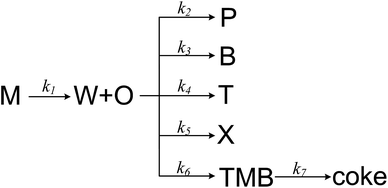 |
| | Fig. 5 The proposed reaction network for MTA process. | |
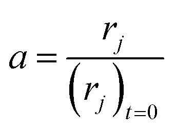
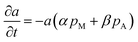
The high linear velocity and small catalyst size minimalize the impact of outer and inner diffusion on catalyst performance, thus the experimental reactor can be treated as a plug flow reactor (PFR).31 Catalyst deactivation at each longitudinal position in the reactor has been characterized by incorporating an activity parameter a, defined as the ratio between the reaction rate at t time on stream and zero time on stream:
| |
 | (2) |
Clearly, a is related to the available active sites for reaction after coke blocks partial acidic sites and pores. There are at least three kinds of active sites in Zn and P co-doped HZSM-5, i.e. (i) Brønsted acid sites, (ii) the original Lewis acid sites of HZSM-5 and (iii) the introduced Lewis acid sites by ZnO incorporation. It has been widely reported that the main reactions such as methanol conversion, hydrogen transfer reaction and olefin aromatization are proceeded over different kinds of active sites, and the coke formation over different acid sites is also diverse from each other.34 That means the effect of deactivation on each reaction is distinct and cannot be quantified by a single parameter a. To balance the accuracy and complexity, we used another factor aO to represent the activity of paraffin and aromatics generation, which is related to activity a with a constant exponent m according to the following expression:
Similar method has been employed by Mier et al.35 in the kinetic modelling of co-reaction of methanol and butane on HZSM-5. As a result, the rate equation of each step is expressed as follows:
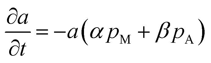
So far, one last problem for model establishment is associating parameter a with operation conditions and TOS. It has been reported that zeolite can be deactivated not only by polyaromatics and less-condensed aromatics, but also by oxygen-containing surface species originated from methanol, and coke deposition is favored by higher-concentrations of oxygenates in the reaction medium (corresponding to a lower-space time).36 Therefore, we take the impact of both methanol and products on coke formation into consideration.
| |
 | (11) |
where
pM and
pA are the partial pressure of methanol and C
6–C
9 aromatics. Here we arbitrarily define
a = 1 at
t = 0.
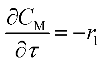
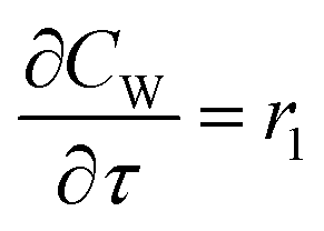
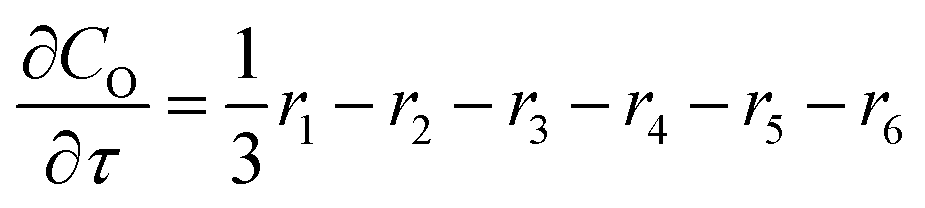
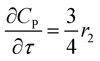
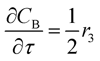
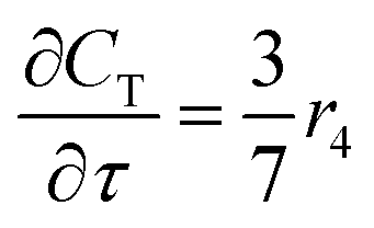
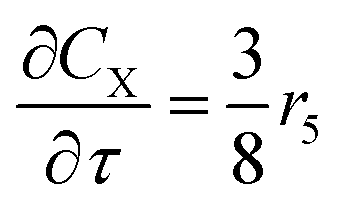
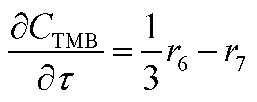
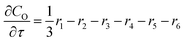
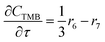
For a further simplification, olefin is represented by propylene while paraffin by butane, as their carbon numbers are close to the average value of corresponding lumped group. Specifically, the generation rates of each lump are as follows:
| |
 | (12) |
| |
 | (13) |
| |
 | (14) |
| |
 | (15) |
| |
 | (16) |
| |
 | (17) |
| |
 | (18) |
| |
 | (19) |
4.2 Numerical method
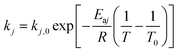
The expression of the rate constant k1–k7 in Arrhenius equation was in the form of reference temperature (723 K), which can reduce the correlation between the pre-exponential factors and activation energies:| |
 | (20) |
Deactivation coefficients α, β were expressed in similar form.
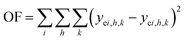
It can be noticed the kinetic model consists of two dimensions: activity a depends on on-stream time t and rate depends on reactor position or space time τ. Here we took the following steps to regress the parameters: first, we discretized τ into n points (in this work, n = 20), and used a 1 × n array a to represent the activity at different reactor position; second, we integrated the activity eqn (11) and calculated the value of a at different on-stream time, and meanwhile solved the rate eqn (12)–(19) with known a at each time step; thirdly, we obtained the calculated reactor outlet composition at different on-stream time. The objective function for optimization is
| |
 | (21) |
where
i denotes for component,
h denote for on-stream time and
k denotes for feed condition.
All the numerical analysis procedure was carried out by Matlab software, during which lsqnonlin function was used for optimization while ode45 function was used for the solution of ordinary differential equation. The confidence interval was obtained from nlparci function with 95% confidence coefficient.
4.3 Parameter results
By fitting the proposed kinetic model with experimental data through the above numerical method, we obtained the pre-exponential factors and the activation energies, as shown in Table 3. The magnitudes of different rate constants agree with the relationship of corresponding experimental yields. The activation energies of C6–C9 aromatics decreases with carbon number, meaning temperature has larger effect on lighter aromatic formation, also in accordance with experimental observation. Compared to α, the smaller value of β indicates the extent of catalyst deactivation with respect to olefin and aromatics is much less significant than methanol, in accordance with previous work.36 The value of m is only 0.13, which means the generation of aromatics and paraffins is less affected by catalyst deactivation than methanol conversion, probably because these two kinds of reactions are proceeded on different active sites.
Table 3 Kinetic parameters determined by fitting the kinetic model to the experimental results
| Parameter |
Pre-exponential factor |
Activation energy, kJ mol−1 |
| k1 |
0.7965 ± 0.0747 mol kg−1 s−1 kPa−1 |
73.18 ± 7.77 |
| k2 |
0.0148 ± 0.0021 mol kg−1 s−1 kPa−1 |
8.89 ± 2.48 |
| k3 |
0.0019 ± 0.0008 mol kg−1 s−1 kPa−1 |
76.83 ± 24.85 |
| k4 |
0.0082 ± 0.0011 mol kg−1 s−1 kPa−1 |
37.50 ± 5.88 |
| k5 |
0.0095 ± 0.0012 mol kg−1 s−1 kPa−1 |
15.45 ± 3.72 |
| k6 |
0.0028 ± 0.0009 mol kg−1 s−1 kPa−1 |
6.60 ± 10.41 |
| k7 |
0.0139 ± 0.0038 mol kg−1 s−1 kPa−1 |
23.18 ± 15.74 |
| α |
0.0800 ± 0.0065 kP−1 h−1 |
104.54 ± 7.83 |
| β |
0.0010 ± 0.0005 kP−1 h−1 |
224.86 ± 25.27 |
| m |
0.13 ± 0.05 |
|
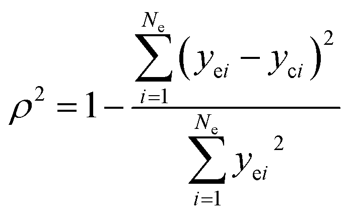
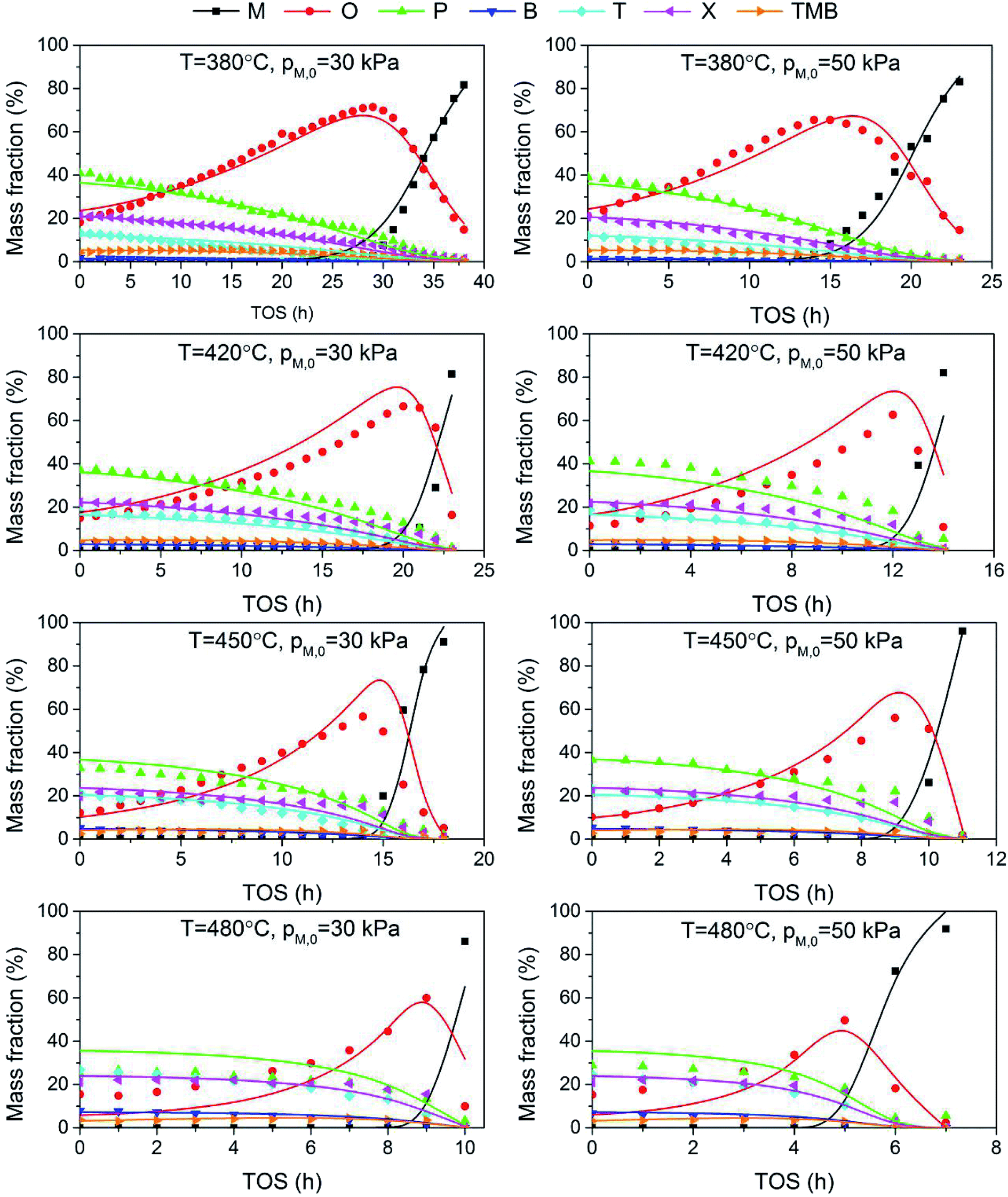
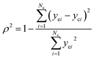
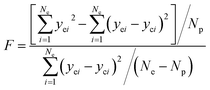
The adequacy of fit is shown in Fig. 6, where the experimental results (points) of lump composition with time on stream are compared with those calculated using the kinetic model (lines). A good agreement between experimental and calculated value can be noticed, in view of the complexity of actual reaction routes. We also adopted two important statistics parameters for the model significance test:25 ρ2 and F, and they are expressed as the following formulas:
| |
 | (22) |
| |
 | (23) |
in which
Ne is the number of experimental points,
Np is the dimension of the model parameters,
yei and
yci are experimental value and calculated value of the dependent variable for the
i-th observation respectively. The larger the two values, the more reliable the model to predict the experimental results. For simplicity,
ρ2 is generally set to be >0.9 as well as
F to be >10
Fα (
Np,
Ne–
Np) (5% significant level). The calculated
ρ2 is 0.944 and
F is 937.74, while the corresponding
Fα is 1.61, which means all the model identification parameters meet the requirements well. Besides, we performed
F-test by Matlab function vartest2 as well, and the returned result shows the null hypothesis is valid likewisely.
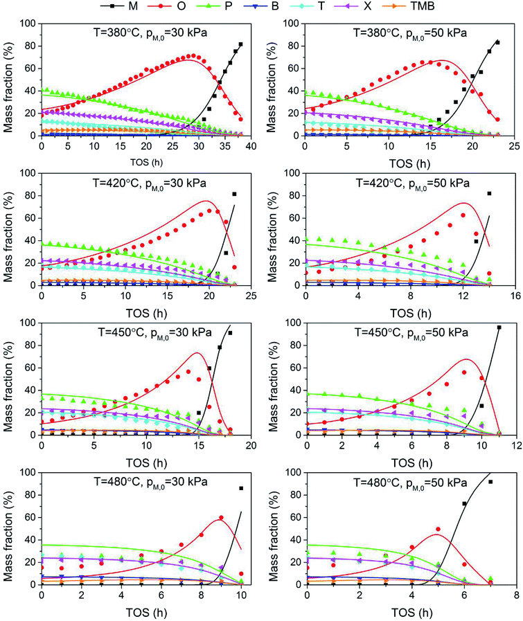 |
| | Fig. 6 Comparison of experimental (points) and calculated (lines) values for the evolution of product composition with time on stream. | |
In the case of MTH process, our previous work established a detailed kinetic model for the generation of paraffins and aromatics from olefin over a high-silica HZSM-5, which gives a good agreement with experimental results in the co-reaction of methanol and olefin. However, as mentioned before, other than the hydrogen transfer over Brønsted acid sites, aromatics can also generate over the Lewis acid sites induced by the adoption of Zn, which complicates the reaction network. Additionally, when feeding methanol alone, how methanol is converted into olefin is still contentious, especially the initial formation of olefin. Some literatures37,38 employed single-event method to establish the micro-kinetic models for MTH process so that the reaction network is simplified into limited number of types of steps, but the model is too complex for process modelling.
The lumped kinetic model simplified the reaction pathway and reduced the number of involved components, and therefore is very useful for large reaction system with ambiguous mechanism. However, it is very tricky to reasonably classify the actual reactants into several homologous lumps, taking accounts of model precision and simplicity. Recently, Li et al.30 proposed a five-lumped kinetic model for methanol conversion to aromatics, but they lumped all the light aromatics (C6–C8) into only one component and therefore it is unable to predict the distribution of key aromatics. On the contrary, we treated the light aromatics individually, which is more useful in practical application. We also associated the activity parameter a with both methanol and products, and a different exponent is used for olefin and aromatics generation, which significantly improved the accuracy of the model prediction.
5. Conclusion
In this work, a reaction network and a corresponding seven-lumped deactivation kinetic model for MTA process have been established based on Zn and P co-modified HZSM-5 in the temperature range of 380–480 °C, including the conversion of methanol into olefin and the generation of paraffin, BTX and trimethylbenzene from olefin. Kinetic experimental data were fitted and analyzed by MATLAB software, and the calculated values agree well with the experiments. Besides, the hypotheses testing indicates that the established model is valid.
Effect of operating conditions on MTA process has also been investigated. Toluene and xylene are the main aromatics while benzene and tryimethylbenzene account for only a small part in all cases. At the same space time, increasing methanol partial pressure and temperature decreases the catalyst lifetime. Higher feed methanol content can lead to less aromatics and more paraffin. Increasing temperature reduces paraffin generation and results in higher aromatic yield, especially benzene and toluene.
Conflicts of interest
There are no conflicts to declare.
Nomenclature
| M, O, W, P, B, T, X, TMB | Methanol, olefin, water, paraffin, benzene, toluene, xylene and trimethylbenzene, respectively |
| a | Activity constant, dimensionless |
| Eaj | Activation energy of j-th reaction, kJ mol−1 |
| kj | Kinetic constant of j-th reaction, mol kg−1 s−1 kPa−1 |
| Ne | Number of experimental points |
| Np | Dimension of the model parameters |
| m | Constant in activity equation |
| OF | Objective function for optimization |
| pi | Partial pressure of i-th component, kPa |
| rj | Rate of j-th reaction, mol kg−1 s−1 |
| wcat | Catalyst weight, kg |
| F | F test parameter |
| FT | Total inlet flow rate, mol s−1 |
| t | On-stream time, h |
| yei | Experimental fraction based on C |
| yci | Caculated fraction based on C |
Greek symbol
| α, β | Deactivation coefficient, kPa−1 |
| ρ2 | Determination factor |
| τ | Space time, kg s mol−1 |
References
- U. Olsbye, S. Svelle, M. Bjørgen, P. Beato, T. V. W. Janssens, F. Joensen, S. Bordiga and K. P. Lillerud, Angew. Chem., Int. Ed., 2012, 51, 5810–5831 CrossRef CAS.
- J. C. Vedrine, P. Dejaifve, E. D. Garbowski and E. G. Derouane, Stud. Surf. Sci. Catal., 1980, 5, 29–37 CrossRef CAS.
- W. O. Haag, R. M. Lago and P. G. Rodewald, J. Mol. Catal., 1982, 17, 161–169 CrossRef CAS.
- X. Huang, H. Li, W.-D. Xiao and D. Chen, Chem. Eng. J., 2016, 299, 263–275 CrossRef CAS.
- C. D. Chang and A. J. Silvestri, J. Catal., 1977, 47, 249–259 CrossRef CAS.
- F. Wang, W. Y. Xiao and G. M. Xiao, Catal. Lett., 2015, 145, 860–867 CrossRef CAS.
- M. Zhao, K. Yuan, Y. Wang, G. Li, J. Guo, L. Gu, W. Hu, H. Zhao and Z. Tang, Nature, 2016, 539, 76–80 CrossRef CAS.
- L. Li, W. Wei, W. Wang, X. Wang, L. Zhang and A. Tian, RSC Adv., 2016, 6, 88277–88286 RSC.
- C. Yang, M. Qiu, S. Hu, X. Chen, G. Zeng, Z. Liu and Y. Sun, Microporous Mesoporous Mater., 2016, 231, 110–116 CrossRef CAS.
- D. Freeman, R. P. K. Wells and G. J. Hutchings, Chem. Commun., 2001, 1754–1755, 10.1039/B104844A.
- P.-C. Lai, C.-H. Chen, H.-Y. Hsu, C.-H. Lee and Y.-C. Lin, RSC Adv., 2016, 6, 67361–67371 RSC.
- D. Freeman, R. P. K. Wells and G. J. Hutchings, J. Catal., 2002, 205, 358–365 CrossRef CAS.
- Y. Ono, K. Osako, G. J. Kim and Y. Inoue, in Studies in Surface Science and Catalysis, ed. H. G. K. H. P. J. Weitkamp and W. Hölderich, Elsevier, 1994, vol. 84, pp. 1773–1780 Search PubMed.
- Y. Inoue, K. Nakashiro and Y. Ono, Microporous Mater., 1995, 4, 379–383 CrossRef CAS.
- D. Zeng, J. Yang, J. Wang, J. Xu, Y. Yang, C. Ye and F. Deng, Microporous Mesoporous Mater., 2007, 98, 214–219 CrossRef CAS.
- M. Conte, J. A. Lopez-Sanchez, Q. He, D. J. Morgan, Y. Ryabenkova, J. K. Bartley, A. F. Carley, S. H. Taylor, C. J. Kiely, K. Khalid and G. J. Hutchings, Catal. Sci. Technol., 2012, 2, 105–112 RSC.
- Y. Gao, G. Wu, F. Ma, C. Liu, F. Jiang, Y. Wang and A. Wang, Microporous Mesoporous Mater., 2016, 226, 251–259 CrossRef CAS.
- Y. Gao, B. Zheng, G. Wu, F. Ma and C. Liu, RSC Adv., 2016, 6, 83581–83588 RSC.
- Y. Ma, D. Cai, Y. Li, N. Wang, U. Muhammad, A. Carlsson, D. Tang, W. Qian, Y. Wang, D. Su and F. Wei, RSC Adv., 2016, 6, 74797–74801 RSC.
- G. F. Froment, K. B. Bischoff and J. D. Wilde, Chemical reactor analysis and design, Wiley, New York, 3rd edn, 2010 Search PubMed.
- X. Huang, D. Aihemaitijiang and W. D. Xiao, Chem. Eng. J., 2015, 280, 222–232 CrossRef CAS.
- X. Huang, D. Aihemaitijiang and W. D. Xiao, Chem. Eng. J., 2016, 286, 150–164 CrossRef CAS.
- B. Jiang, X. Feng, L. Yan, Y. Jiang, Z. Liao, J. Wang and Y. Yang, Ind. Eng. Chem. Res., 2014, 53, 4623–4632 CrossRef CAS.
- P. Pérez-Uriarte, A. Ateka, A. T. Aguayo, A. G. Gayubo and J. Bilbao, Chem. Eng. J., 2016, 302, 801–810 CrossRef.
- M. Wen, J. Ding, C. Wang, Y. Li, G. Zhao, Y. Liu and Y. Lu, Microporous Mesoporous Mater., 2016, 221, 187–196 CrossRef CAS.
- M. Menges and B. Kraushaar-Czarnetzki, Microporous Mesoporous Mater., 2012, 164, 172–181 CrossRef CAS.
- S. N. Khadzhiev, M. V. Magomedova and E. G. Peresypkina, Pet. Chem., 2015, 55, 503–521 CrossRef CAS.
- T.-Y. Park and G. F. Froment, Ind. Eng. Chem. Res., 2001, 40, 4172–4186 CrossRef CAS.
- P. Kumar, J. W. Thybaut, S. Svelle, U. Olsbye and G. B. Marin, Ind. Eng. Chem. Res., 2013, 52, 1491–1507 CrossRef CAS.
- N. Li, C. Meng and D. Liu, Fuel, 2018, 233, 283–290 CrossRef CAS.
- W. Wu, PhD dissertation, East China University of Science and Technology, 2012.
- C. Song, K. Liu, D. Zhang, S. Liu, X. Li, S. Xie and L. Xu, Appl. Catal., A, 2014, 470, 15–23 CrossRef CAS.
- S. Müller, Y. Liu, M. Vishnuvarthan, X. Sun, A. C. van Veen, G. L. Haller, M. Sanchez-Sanchez and J. A. Lercher, J. Catal., 2015, 325, 48–59 CrossRef.
- D. Mier, A. G. Gayubo, A. T. Aguayo, M. Olazar and J. Bilbao, AIChE J., 2011, 2841–2853 CrossRef CAS.
- D. Mier, A. G. Gayubo, A. T. Aguayo, M. Olazar and J. Bilbao, AIChE J., 2011, 57, 2841–2853 CrossRef CAS.
- A. G. Gayubo, A. T. Aguayo, M. Olazar, R. Vivanco and J. Bilbao, Chem. Eng. Sci., 2003, 58, 5239–5249 CrossRef CAS.
- G. F. Froment, Catal. Rev., 2005, 47, 83–124 CrossRef CAS.
- P. J. Becker, N. Serrand, B. Celse, D. Guillaume and H. Dulot, Fuel, 2016, 165, 306–315 CrossRef CAS.
|
| This journal is © The Royal Society of Chemistry 2019 |
Click here to see how this site uses Cookies. View our privacy policy here. 
 Open Access Article
 This Open Access Article is licensed under a Creative Commons Attribution-Non Commercial 3.0 Unported Licence
 *
*