DOI:
10.1039/C9RA02240F
(Paper)
RSC Adv., 2019,
9, 17766-17777
Tailor-made high-performance reverse osmosis membranes by surface fixation of hydrophilic macromolecules for wastewater treatment†
Received
23rd March 2019
, Accepted 30th May 2019
First published on 6th June 2019
Abstract
Polyamide aromatic (PA) reverse osmosis (RO) membranes are currently the most important materials in the seawater desalination and wastewater treatment industry. This study used hydrophilic macromolecular polyvinylpyrrolidone (PVP) in a PA selective layer to develop a new polyamide thin-film composite (TFC), namely PA-g-PVP RO, which will be used for water treatment. The TFC is prepared via an interfacial polymerisation process, and TFC-based PVP can be transplanted on a PA surface by radiation. PA-g-PVP RO was characterised by ATR-FTIR, SEM, XPS, AFM and contact angle test and then evaluated by determining its permeability, salt retention and antifouling performance, among other properties. Results show that the chemical composition and surface morphology of the polyamide film significantly changed. A PVP brush grafted on an RO membrane surface significantly enhanced the hydrophilicity and antifouling performance of the membrane. When the PVP concentration was increased in an aqueous solution to 2%, the water contact angle of the sacrificial layer of the modified membrane decreased to 24.3°, the fouling recovery ratio to 93.4% and the salt retention increased to 99.5% at a small flux change. This combined technology can also be used for other macromolecules to modify the membrane and study the preparation and modification of ultra-filtration and nano-filtration membranes.
1. Introduction
In recent years, increasing population growth and decreasing surface water and usable ground water supply have led to a serious lack of usable fresh water resource all over the world, which has become a global issue that restricts economic development and human survival.1–3 As a saline-alkali water purification process, seawater desalination provides fresh water for human life and industrial and agricultural production and is regarded as a feasible method to mitigate the global water shortage crisis.4,5 In the currently developed membrane-based desalination processes, reverse osmosis (RO) membranes play a leading role in the seawater desalination industry because of their advantages in comprehensive energy consumption, capital cost and so forth.6 As the most frequently used RO membrane, polyamide thin-film composite (TFC) has advantages such as high flux and salt retention, wide operation temperature and pH ranges and convenient operation.7,8 In spite of these advantages, polyamide RO membrane still faces a serious contamination challenge. TFC RO membrane is inherently sensitive to dirt, and the accumulating dirt during seawater desalination and wastewater treatment lead to slower flow, poorer water quality and shorter membrane life. Thus, enhancing the antifouling performance of polyamide RO membrane is a necessary and significant endeavour.9–11
Membrane contamination is a process where dirt settles down or is adsorbed on the membrane surface, depending on multi-interactions between membrane surface and dirt.12 Numerous studies show that membranes with low hydrophilicity and modification surface have good antifouling performance. The possible antifouling mechanism is that nonreversible membrane contamination can be mitigated by preventing dirt adsorption or settlement because high hydrophilicity of the membrane surface helps form a hydration layer on the surface.13–15 The attached dirt is also more easily removed from the membrane surface by hydrodynamic shear force (self-cleaning performance) to reduce the degree of reversible membrane contamination. Thus, many antifouling materials have been used for surface modification, such as polyvinyl alcohol, polyethylene glycol and graphene oxide.11,16,17 As a synthetic water-soluble polymeric compound, PVP has a strong affinity for water molecules and has many good features, including chemical stability, good bioinertia and antifouling before settlement. However, it is very difficult to fix PVP on the RO membrane surface because PVP has no active functional group, which restricts the application of PVP to the RO membrane. PVP is seldom used for RO membrane surface decoration to enhance the hydrophilicity and antifouling performance of the membrane.18
Moreover, the modification methods in many reports may be unpractical for industrial production. During long-term operation and chemical cleaning, the physically applied coating can be unstable. Although many covalent grafting methods can maintain the stability of the modified layer, the modification technique requires complicated synthesis conditions. The modification process may likewise reduce the membrane flux or retention.19 A more efficient, time-saving and appropriate method for membrane modification is the main development trend now. The γ-ray radiation-initiated grafting method is very attractive because of its low cost and ease of operation.20 Most of the radiation energy is absorbed by water when the aqueous solution of a polymer is radiated, resulting in the formation of short reactivity radicals. Interestingly, in this case, OH− radicals and H atoms are capable of abstracting H atoms from macromolecules, resulting in the production of polymer radicals. Davis et al. first proposed the structure of poly(n-vinyl pyrrolidone) produced in the oxygen-free aqueous solution of PVP.21 They studied the radiation-induced inter-molecule and intermolecular cross-linking mechanism of the PVP chain and found that the radicals formed after radiation were methylene (3) and methylidene (4) groups, as shown in Fig. 1. In addition, they provided a theoretical basis for PVP macromolecule grafting on a membrane surface.20,22
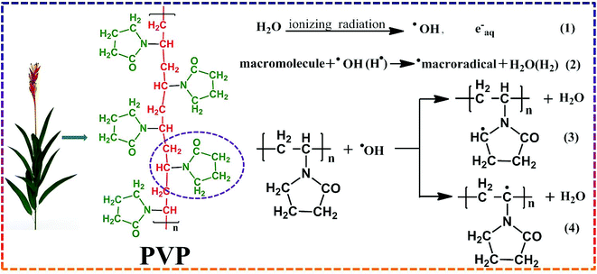 |
| | Fig. 1 Schematic overview of hydrogen abstraction from PVP by hydroxyl radical. | |
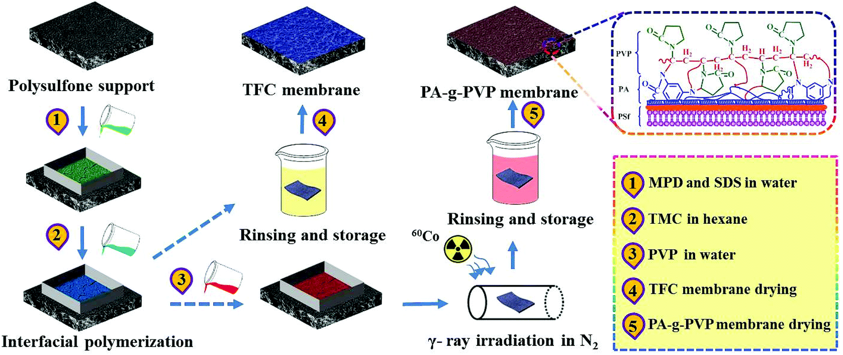
The purpose of this study is to find a simple and efficient method for polyamide RO membrane modification. First, the primary TFC RO membrane was prepared by interfacial polymerisation (IP) technique. Then, the grafting agent (PVP) was added under radiation to prepare the novelty PA-g-PVP RO membrane, which was comprehensively characterised by ATR-FTIR, XPS, SEM, AFM and so on. The radiation condition, grafting agent concentration and gas influencing factors, among other properties, were discussed in detail. Bovine serum albumin (BSA) protein was then used to evaluate the antifouling performance of the membrane. The results suggested that the novel PA-g-PVP RO membrane has great potential in seawater desalination and wastewater treatment.
2. Experimental section
2.1. Materials and reagents
The porous support material of RO membrane was purchased from Beijing OriginWater Technology Co. Ltd. (China) by PSf membrane. The 1,3,5-trimesoyl chloride (TMC, ≥98%), sodium dodecyl sulfate (SDS, 98%) and m-phenylenediamine (MPD, 99%) purchased from Aladdin Reagent Co. Ltd. (Shanghai, China) and West Long Chemical Co. Ltd. (China) respectively and used for prepare PA-TFC RO membrane through interfacial polymerization (IP) technique. Branched polyvinyl pyrrolidone (PVP, with different average molecular weight of 58![[thin space (1/6-em)]](https://www.rsc.org/images/entities/char_2009.gif) 000, 24000 and 8000) were purchased from Aladdin Reagent Co. Ltd. (Shanghai, China). Bovine serum albumin (BSA) with 98% purity supplied by West Long Chemical Co. Ltd. (China) acted as foulants for the assessment of antifouling performance by monitoring its water flux change as a function of filtration time. N-hexane and sodium chloride (NaCl) were provided by Tianjin Kermel Chemical Reagent Co., Ltd. (China). All chemicals were used as received without further purification. All used water was deionized.
000, 24000 and 8000) were purchased from Aladdin Reagent Co. Ltd. (Shanghai, China). Bovine serum albumin (BSA) with 98% purity supplied by West Long Chemical Co. Ltd. (China) acted as foulants for the assessment of antifouling performance by monitoring its water flux change as a function of filtration time. N-hexane and sodium chloride (NaCl) were provided by Tianjin Kermel Chemical Reagent Co., Ltd. (China). All chemicals were used as received without further purification. All used water was deionized.
2.2. Preparation of PA-g-PVP RO membrane
RO membrane modification included two steps as shown in Fig. 2. TFC RO membrane was synthesized on PSf-supported membrane by IP process. Firstly, PSF membrane (13.2 cm × 7.4 cm) was fixed in a polytetrafluoroethylene frame, 2.5% (w/v) MPD and 0.12% (w/v) SDS aqueous solutions were injected to its surface, kept for 120 s, and the excessive aqueous solutions were blown away from the membrane surface. Then, 0.1% (w/v) TMC-containing n-hexane solution was injected to the membrane surface for 60 s' IP reaction at room temperature. The membrane was rinsed with pure n-hexane to remove residual TMC. Finally, the membrane was dried at 70 °C for 5 min, thoroughly flushed and stored in deionized (DI) water. This membrane was named TFC RO membrane. The modified membrane was produced in the similar process to TFC, but in a different modification, as shown in Fig. 2. After IP, TFC RO membrane was placed in a frame, and only the top surface was coated. 0–5% (w/v) PVP aqueous solutions were added to the membrane. The frame and membrane were placed to a glass radiation tube. The membrane and grafting solution were degassed, and radiated by γ-ray at the desired radiation dose (0–100 kGy). After that, the modified membrane was thoroughly washed with deionized water at 45 °C to remove residual PVP and ungrafted polymer. This membrane was named modified PA-g-PVP RO membrane. All the membrane specimens were stored in deionized water for later test.
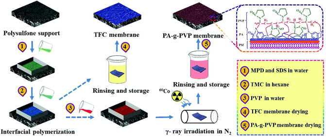 |
| | Fig. 2 Schematic overview of fabrication process for PA-g-PVP RO membrane via multistep interfacial polymerization. | |
2.3. Characterization of RO membrane
The surface chemical composition and structure of the supports were studied by ATR-FTIR (Model: AVATAR360, Thermo Nicolet Corporation, USA) and XPS (Model: Escalab250Xi, Thermo Scientific, USA). Each ATR-FTIR spectrum results in an average of 50 scans in the range of 3600–1050 cm−1 at 1 cm−1 resolution. The XPS scans were described for binding energies ranging from 1000 to 0 eV. High resolution scans were acquired by averaging 10 scans for C (1s) peaks.23 The surface and section morphology of TFC RO membrane and PA-g-PVP RO membrane were described through field emission scanning electron microscopy (FE-SEM, Supra55, Zeiss Co., Germany). Before imaging, RO membranes were soaked in liquid nitrogen, cut by a sharp blade, and then paint a layer of gold. Membrane surface morphology was also measured by atomic force microscopy (AFM, Dimension Fastscan, Bruker Co., USA) analysis and imaging. In the AFM study, the RO membranes with an area of 10 μm × 10 μm were scanned, the average roughness of samples was calculated using software installed on AFM equipment.24 The contact angle and surface energy of the membrane surface were measured using contact angle goniometer (Model: SL200KB, Shanghai Solon Co., China), deionized water and glycol as the liquid.
2.4. Evaluation of RO membrane on filtration performance
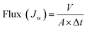
Water flux and NaCl rejection of the prepared virgin TFC RO and the modified PA-g-PVP RO membranes were evaluated using a cross-flow filtration test setup (Model: TYLG-08, Jinan Bono Biotechnology Co. Ltd.), its schematic is shown in Fig. S1.† Both permeate and retentate were recycled back to the feed tank during the tests. All penetrant and retention fluids were recycled back to the feed tank during the test. Testing membrane sample was cut and positioned in the test cell (effective membrane surface area: 6.48 cm−2). First, the membranes were compacted at pressure of 20 bar for 2 h. When the membrane water flux reaches a steady state, the membranes were tested with the NaCl aqueous solution (2000 ppm), temperature of 25.0 ± 0.5 °C, transmembrane pressure (TMP) of 15.5 bar, performance data were collected after 1 h. The water flux was determined from the following eqn (1):| |
 | (1) |
where Jw is the permeate water flux (L m−2 h−1), V is the volume of the penetrant collected for testing (L), Δt (h) is the test time and A is the effective membrane surface area (m2).
The salt rejection performance was assessed with 2000 ppm NaCl feed concentration, and the ratio of desalinization was calculated by using the eqn (2):
| |
 | (2) |
where
Cf and
CP represent the feed and permeate solutions salt concentration, respectively. These two concentrations were measured using a conductance meter (DDSJ-308F, Shanghai Precision Instrument Co. Ltd., China). All membrane samples were tested at least 6 times, and the average value of the data was obtained.
2.5. Evaluation of RO membrane antifouling property and long-term stability
In the experiment on estimating antifouling performance, BSA was used as a protein foulant.25 The antifouling ability of the RO membranes was evaluated via the flux recovery ratio (FRR) [eqn (3)], irreversible flux decline ratio (DRir) [eqn (4)], reversible flux decline ratio (DRr) [eqn (5)] and total flux decline ratio (FDR) [eqn (6)]. The respective equations are as follows:| |
 | (3) |
| |
 | (4) |
| |
 | (5) |
| |
 | (6) |
The experiment was conducted according to the following procedure. Antifouling ability test was conducted in circulation mode and then the NaCl aqueous solution (2000 ppm) was added to the feed liquid (100 ppm of BSA solution) to avoid the influence of concentration polarisation. The initial permeation flux of water (Jw0) was acquired by measuring 2000 ppm NaCl aqueous solution for 1 h. The initial permeation flux of water (Jw0) was 28.6 L m−2 h−1, temperature was 25.0 ± 0.5 °C and pH was 7. The feed solution was then assessed and tested for 4 h, during which the real-time water flow rate and salt retention rate were recorded every 5 min and the foulant solution flux (Jwt) was measured. Finally, all the mixed solution was emptied out and the membrane was rinsed with deionised water for 1 h and re-estimated for water flux (Jwf) under the same TMP. The process of 4 h foulant solution filtration and 1 h deionised water rinsing was defined as one ‘filtration rinsing’ cycle.18,25 This procedure was repeated three times. The stability of the modified RO membrane was studied by conducting a 168 hour cross-flow test with 2000 ppm NaCl as the feed solution at 15.5 bar and 25.0 ± 0.5 °C. All of the penetrating fluids were collected back into the fluid tank to maintain constant salt concentrations.
3. Results and discussion
3.1. Membrane surface characterisation
3.1.1. FTIR analysis. ATR-FTIR was used to verify the PVP-grafted polyamide membrane surface.26 The infrared spectra of TFC as primary membrane (Fig. 3) showed main characteristic peaks of PA layer and polysalfone-supporting layer. A stretching peak of Ar–O–Ar (Ar represents aromatic ring) appeared in the supporting layer at 1245 cm−1.27 At 1540, 1608, 1660 and 3300 cm−1 were the plane bending peak of N–H (amine II), stretching peak of H-bound C![[double bond, length as m-dash]](https://www.rsc.org/images/entities/char_e001.gif) O (amine I), stretching peak of CO (amine I) and stretching vibration peak of N–H, respectively, all of which were the characteristic peaks of polyamide aromatic.28,29 There was no characteristic peak of acyl chloride at 1770 cm−1, indicating that all the monomers completely reacted during membrane formation. FTIR spectra of PA-g-PVP RO membrane clearly showed the absorption peaks from 1420 cm−1 to 1450 cm−1 produced by the wagging vibration of –CH2– in PVP. The peaks from 2900 cm−1 to 2960 cm−1 were attributed to the asymmetric and symmetric stretching vibration of the C–H bond.30 Peak intensity was also enhanced by introducing PVP. The stretching peak of N–H at 3300 cm−1 disappeared, but the relative intensity of the stretching peak of C–N at 1290 cm−1 was enhanced, indicating that the most possible grafting sites were the amido group and carboxylic acid end group in the PA chain, as discussed in the background section.31 The PA-g-PVP RO membrane had higher peak intensity at 1660 and 1608 cm−1 in the FTIR spectra in Fig. 3 than TFC because (1) PVP grafting on the PA membrane surface contributed to carbonyl content, and (2) PVP as hydrophilic macromolecule indirectly led to an increase of peak intensity at 1608 cm−1. All the data showed that PVP molecules could be fixed on the PA membrane surface by radiation.
O (amine I), stretching peak of CO (amine I) and stretching vibration peak of N–H, respectively, all of which were the characteristic peaks of polyamide aromatic.28,29 There was no characteristic peak of acyl chloride at 1770 cm−1, indicating that all the monomers completely reacted during membrane formation. FTIR spectra of PA-g-PVP RO membrane clearly showed the absorption peaks from 1420 cm−1 to 1450 cm−1 produced by the wagging vibration of –CH2– in PVP. The peaks from 2900 cm−1 to 2960 cm−1 were attributed to the asymmetric and symmetric stretching vibration of the C–H bond.30 Peak intensity was also enhanced by introducing PVP. The stretching peak of N–H at 3300 cm−1 disappeared, but the relative intensity of the stretching peak of C–N at 1290 cm−1 was enhanced, indicating that the most possible grafting sites were the amido group and carboxylic acid end group in the PA chain, as discussed in the background section.31 The PA-g-PVP RO membrane had higher peak intensity at 1660 and 1608 cm−1 in the FTIR spectra in Fig. 3 than TFC because (1) PVP grafting on the PA membrane surface contributed to carbonyl content, and (2) PVP as hydrophilic macromolecule indirectly led to an increase of peak intensity at 1608 cm−1. All the data showed that PVP molecules could be fixed on the PA membrane surface by radiation.
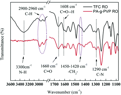 |
| | Fig. 3 ATR-FTIR spectra of nascent membrane TFC RO and PA-g-PVP (PVP-58000-2%) RO membranes. | |
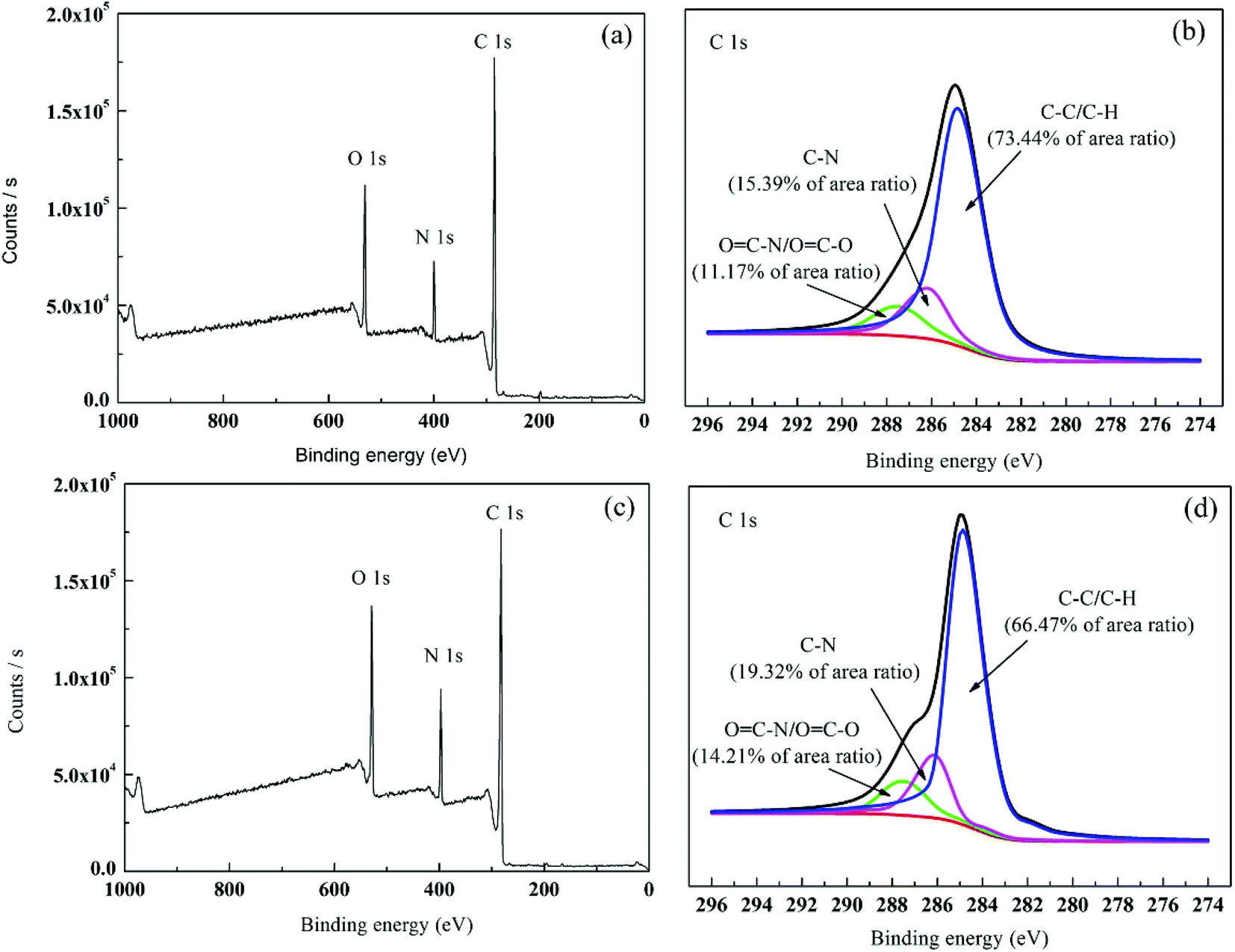
3.1.2. XPS analysis. XPS is highly sensitive to the surface and can determine the element composition and chemical combination at the depth of 1–5 nm in the surface.32 The chemical change of aromatic compound was further determined by XPS analysis of the membrane surface. In general, the elements did not significantly change between primary membrane and modified membrane because the co-polymer in TFC showed the same chemical composition. The elements detected by XPS include oxygen (O), nitrogen (N) and carbon (C). Table 1 summarises the elements in the two membranes. Fig. 4 and Table 1 show that after PVP graft polymerisation, the N and O contents of the membrane significantly increased. For example, the O content increased from 10.52% to 11.80% and the N content increased from 16.10 to 16.59% because PVP had higher N and O atom contents than the primary membrane. An increase in N and O atom concentrations led to more polar groups (such as CO–H) on the modified membrane surface. Therefore, the membrane was more hydrophilic. The measured contact angle in Section 3.1.4 proved the increase in membrane surface hydrophilicity. The C 1s core-level spectra of the TFC and PA-g-PVP RO membranes are shown in Fig. 4. Three peak values with binding energies of 283.3, 284.6 and 286.2 eV (Fig. 4a) were assigned to C–C/C–H, C–N and OC–N/OC–O, respectively.8,31,32 For the modified membrane, the change of peak areas at 283.3, 284.6 and 286.2 eV was observed, suggesting that the chemical structure of the membrane surface changed. The XPS analysis results also proved that PVP was successfully fixed on the membrane surface.
Table 1 Element contents of TFC RO and PA-g-PVP (PVP-58000-2%) RO membranes
| Membrane |
Atomic percentage from XPS (at%) |
| C |
O |
N |
| TFC RO |
73.38 |
10.52 |
16.10 |
| PA-g-PVP RO |
71.61 |
11.80 |
16.59 |
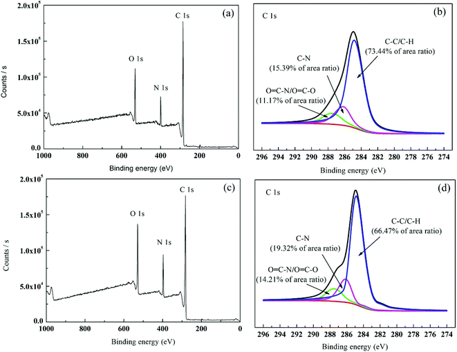 |
| | Fig. 4 XPS survey spectra: (a and b) wide-scan and C1s core-level spectrum for TFC RO membrane; (c and d) wide-scan and C1s core-level spectrum for PA-g-PVP (PVP-58000-2%) RO membrane. | |
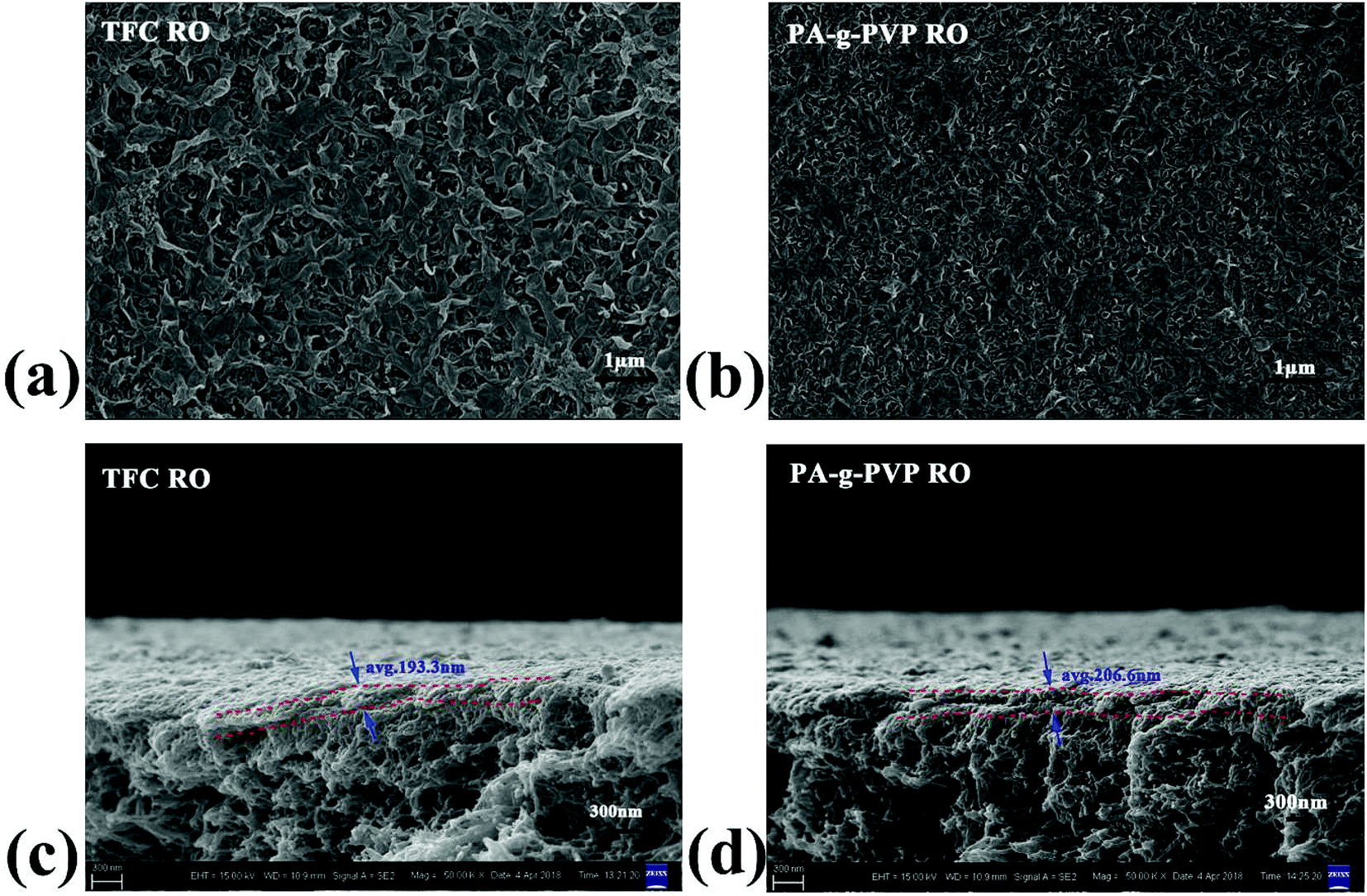
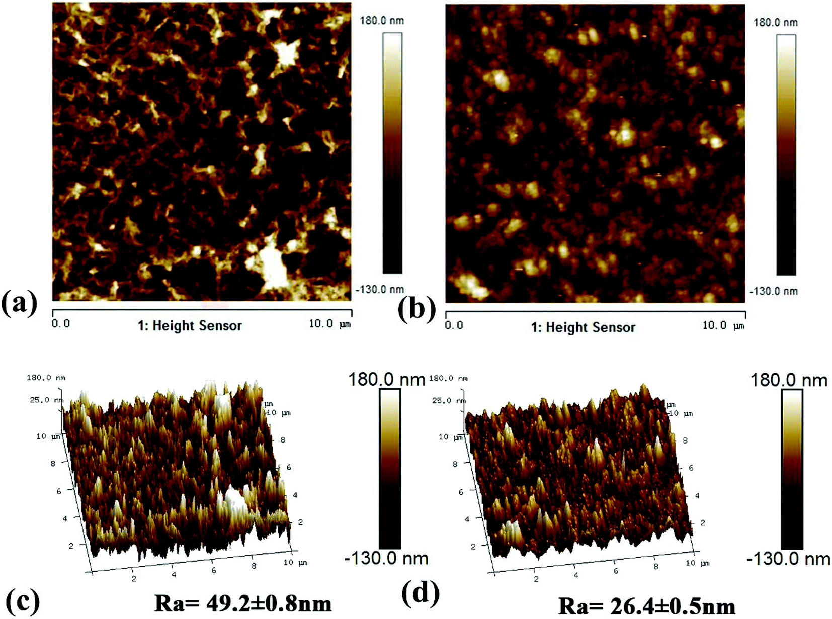
3.1.3. Morphology analysis. The morphological structure of the membrane was studied using SEM and AFM.24,33 Fig. 5 shows the surface and cross-section scanning micrograms of the primary and modified RO membranes. The results indicated that all the composite membranes showed typical surface leaf-like and ridge-and-valley structures.34 The PA-g-PVP RO membrane had thinner PA node and modified surface than the primary TFC RO membrane. The leaf-like and ridge-and-valley microstructures were weakened on the PA-g-PVP membrane (Fig. 5b) surface. In the SEM image of the cross section, the PA-g-PVP membrane (Fig. 5d) showed more uniform skin layer than the traditional TFC RO membrane (Fig. 5c).35,36 When the PVP content reached 2%, the thickness of the selective skin layer of the composite membrane slightly changed and measured 206.6 nm on average. The membrane surface morphology was further observed by AFM to obtain 2D and 3D images and quantify the surface roughness. As shown in Fig. 6, the surface roughness of the traditional TFC RO membrane was 49.2 nm (Fig. 6c), which accorded with the value reported in literature, and the PA-g-PVP RO membrane showed lower Ra at ∼26.4 nm and modified surface (Fig. 6d). Both the primary and modified membranes showed typical peak-and-trough surface morphology, and the PA-g-PVP RO membrane showed more significant physical irregularity.37 Moreover, hydrophilic macromolecules were filled in the surface peak-and-trough so that the membrane surface became modified and showed less roughness, which is one of the key features to reduce the fouling performance of the membrane.38
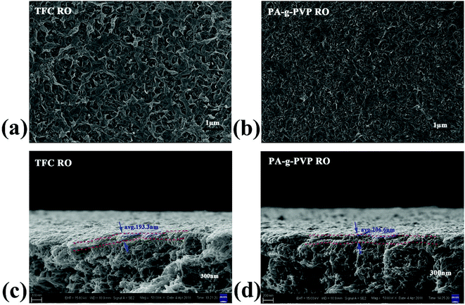 |
| | Fig. 5 Top surface SEM (a) and cross-section SEM (c) images of TFC RO membrane, Top surface SEM (b) and cross-section SEM (d) images of PA-g-PVP RO membrane. | |
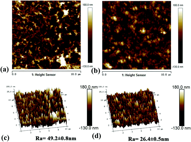 |
| | Fig. 6 AFM 2D (a) and 3D (c) images of the TFC RO membrane, AFM 2D (b) and 3D (d) images of the PA-g-PVP RO membrane. All of membranes for AFM were freeze-dried for 10 h and then tested in a scan size of 10 μm × 10 μm. | |
3.1.4. Contact angle and surface energy analysis. Hydrophilicity of the membrane surface is one of the most important factors that influence the permeability and antifouling performance of the membrane.39 A low contact angle generally represents the high hydrophilicity of the surface, while a high hydrophilicity membrane not only increases the water flux but also decreases the membrane surface contamination.14 As shown in Fig. 7, the static and time-dependent water contact angles of the TFC RO membrane and the modified membrane surfaces were measured to study the hydrophilicity of these membrane surfaces. Obviously, the hydrophilicity of the modified membrane increased by increasing the amount of PVP concentration compared with the TFCRO membrane.39,40 Compared with the TFCRO membrane, water contact angle of the PA-g-PVP RO membrane decreased from 51.4° to 24.4°. Hydrophilicity increased because the synergetic effect of these hydrophilic groups, such as carbonyl, exceeded the effect caused by the roughness reduction after the hydrophilic material was fixed on the membrane surface. Moreover, when the PVP concentration reached 5%, the contact angle slightly increased, which could be caused by the increased PVP re-polymerisation and self cross-linking degree under radiation conditions.41 The hydrophilic angle of the membrane surface likewise decreased with the increasing molecular weight of PVP, while the water contact angle of PVP-58000-2% decreased from 24.4° to 0° within 3 min. To further verify the hydrophilicity of the membrane surface, the energy and adhesive work of the membrane surface were characterised and listed in Table S1.† PA-g-PVP RO membranes showed higher total surface energy and adhesive work than TFC RO membranes. High total surface energy and adhesive work mean stronger polarity and hydrophilicity.42 In addition, the hydrophilic PVP fixed on the membrane surface caused it to adhere to many water molecules, finally forming a hydration layer, promoting the water molecules to quickly penetrate the membrane and helping reduce membrane contamination.39,43
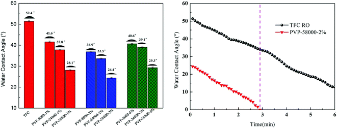 |
| | Fig. 7 Surface water contact angle values and function of time of composite membranes measured with de-ionized water at 25.0 °C. | |
3.2. Membrane fabrication: the effect of polymer composition
The molecular weight of the grafting agent is very important for the formation of the RO membrane.42 PA-g-PVP RO membranes show different structures and properties, even at the same PVP concentration, because the same quantity of PVP with different molecular weights have different molar ratios. Thus, we studied the relationship between the structure and performance of the membrane and the molecular weight of PVP at the same mass concentration. Fig. 8a shows the flux and reject reaction of the RO membrane at different molecular weights of PVP (PVP58000, PVP24000 and PVP8000) at the same mass concentration (2%), radiation dose (20 kGy) and condition (N2 atmosphere). When the molecular weight of PVP was decreased, the flux of the PA-g-PVP RO membrane decreased as well compared with the primary TFCRO membrane. The PA-g-PVP RO membrane showed much higher retention than the TFC RO membrane, and its retention gradually increased with decreasing molecular weight. The PA-g-PVP RO membrane had optimal performance when the molecular weight of PVP was 58000, which could be caused by the different optimal molar ratios of PVP in different studies. In the current study, the molar ratio of PVP58000 was closer to the optimal molar ratio. Thus, the membrane showed optimal performance at the PVP58000 concentration of 2% w/v. Fig. 8b also proves the assumption that the thickness of the top layer increased from 193.3 nm to 207.8 nm and the molecular weight of PVP increased from 58000 to 8000. Considering the increase of relative mole, these findings are rational and prove the re-polymerisation effect of PVP. Many recent studies showed that the increase in thickness of the membrane would lead to a decrease in flux, and the increase in crosslinking degree would lead to an increase in retention.41,44 The PA-g-PVP RO membrane also had a considerably lower surface roughness than the TFC RO membrane, and the modified membrane surface helped prevent contamination.
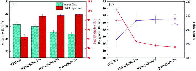 |
| | Fig. 8 (a) Filtration performance (water fluxs and salt rejections) and (b) Separation layer structure (surface roughness and thickness) of the composite membranes by varying the PVP average molecular weight while keeping the 2% (w/v) PVP concentration and irradiation dose (20 kGy) constant. | |
3.3. Membrane fabrication: effect of the grafting agent concentration
Grafting agent concentration during modification is one of the key parameters of the structure and performance of RO membrane.45 Thus, PVP concentration was systematically controlled in order to produce the PA-g-PVP RO membrane with optimal performance. Fig. 9a shows that the water flux and NaCl retention of the RO membrane were controlled by changing the PVP concentration at constant relative molecular weight (PVP58000) and radiation dose (20 kGy). Moreover, the results showed that the NaCl retention was increased to 99.7% (max.) by increasing the PVP concentration, and all the membrane fluxes decreased. As shown in Fig. 9, hydrophilic PVP grafting on the membrane surface strengthened the hydrophilicity, which could theoretically increase the water flux. In addition, higher membrane thickness and crosslinking degree, which inhibited the water flux to some extent but significantly increased salt retention because of the salt rejection of the membrane, mainly depended on the crosslinking density of the PA layer.46 The primary membrane was radiated at the PVP concentration of 0%. Results also showed that the membrane flux slightly decreased and the retention increased, in agreement with the results reported by other researchers.20 Radiation is believed to be capable of causing the PA layer to re-polymerise and crosslink, thus resulting in a higher crosslinking density.
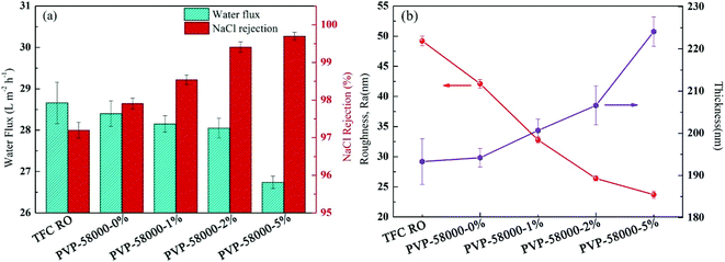 |
| | Fig. 9 (a) Filtration performance (water fluxs and salt rejections) and (b) separation layer structure (surface roughness and thickness) of the composite membranes by varying the PVP concentration while keeping the irradiation dose (20 kGy) constant. | |
To understand the relationship between membrane structure and performance, the surface thickness and roughness of the PA layer at varying PVP concentrations were evaluated (Fig. 9b). The results showed that with increasing PVP concentration, the surface roughness gradually decreased and the thickness of the PA layer gradually increased, in agreement with the results reported in other studies.41 Therefore, a thick PA layer could be formed at high PVP concentration. However, an increase of surface thickness and crosslinking density could influence the water flux, resulting in a decrease of total membrane water flux at higher PVP concentration. Thus, based on the experimental results, PVP concentration was set to 2% as an optimal concentration in all the subsequent studies.
3.4. Membrane fabrication: effect of irradiation doses
The γ-ray radiation during membrane modification could enhance the crosslinking degree, promote re-polymerisation of the grafting agent and PA layer and, therefore, increase the separation efficiency and membrane performance. However, excessive radiation was reported to have an adverse impact on membrane performance, such as membrane degradation.47 Thus, to find the optimal radiation dose, membrane performance was evaluated as the function of radiation dose at constant molecular weight (58000) of PVP and constant PVP concentration (2%), as shown in Fig. 10a. With the increasing radiation dose to 40 kGy, NaCl retention greatly increased to its maximum and then decreased. Philippe Moulin et al. also observed that such salt rejection trend occurs under γ-ray radiation.20,47 As the experiment started at a low radiation dose (5–40 kGy), the dose was increased by strengthening the radiation energy and promoting the radical formation to promote the grafting reaction, resulting in an increase of PA crosslinking density and, therefore, an increase in salt retention. However, a further increase of radiation dose would lead to the production of micelles, which would sharply increase the PA layer thickness. An excess of dose would likewise lead to polyamide degradation, which results in unwanted defects or a damaged crosslinking network of the PA layer because of more serious membrane repulsion at a higher radiation dose. In addition, the water flow changed in a similar trend to retention. Fig. 10b illustrates that with increasing radiation dose, the surface roughness increased, Ra gradually decreased, though insignificantly, and PA layer thickness gradually increased. A high radiation dose would lead to a thick reaction zone, which is not good for water permeation. At a higher radiation dose (above 60 kGy), an increase of crosslinking density and thickness and possible formation of micelles and degradation would lead to a decrease of water flow and retention of the membrane.20,47 Based on the experimental results, the optimal radiation dose was determined as 20 kGy.
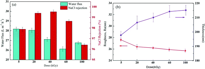 |
| | Fig. 10 (a) Filtration performance (water fluxs and salt rejections) and (b) Separation layer structure (surface roughness and thickness) of the composite membranes by varying the irradiation dose while keeping the 2% (w/v) PVP concentration constant. | |
3.5. Membrane fabrication: effect of different gas conditions
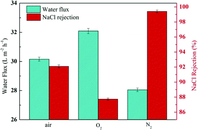
The N–H bond of the amide and amino groups on the TFC RO membrane could be further induced for self-polymerisation and polyamide grafting on PVP by radiation, which was performed during modification after IP reaction and resulted in further densification of the PA layer. However, it was also reported that radiation under different gas conditions might lead to support and sacrificial layer collapse and even cracking, resulting in decreased membrane performance.22 Thus, finding the suitable gas conditions for radiation is crucial. The membrane performance at constant radiation dose and PVP concentration was monitored to find the optimal modification conditions, as shown in Fig. 11. A membrane was modified in oxygen, nitrogen and air by radiation. Results indicated that the modified membrane flux greatly increased and the retention decreased from 97.2%, and those of primary membrane to 92.1% and 87.7% in air and oxygen, respectively, because oxygen could oxidatively degrade PA and PVP under radiation conditions to form collapsing caves, resulting in serious deterioration of the modified membrane performance. These findings were found to be in agreement with the results reported in other studies.47 Thus, we selected nitrogen atmosphere to modify the membrane. As shown in Fig. 11, based on the unchanged and even a slight increase of the flux, the modified membrane retention was increased to 99.4%. The experimental result indicated that the optimal radiation atmosphere was determined as nitrogen.
 |
| | Fig. 11 Filtration performance (water fluxs and salt rejections) of the composite membranes by varying the gas conditions while keeping the PVP concentration and irradiation dose (20 kGy) constant. | |
3.6. Evaluation of membrane antifouling performance and long-term stability
To study the antifouling performance of membranes, BSA (100 mg L−1) was used as the dirt for the model protein to perform the filtration, cleaning and circulation tests on membranes.48 The test was performed at the same initial flow by adjusting TMP to minimise the effect of transverse hydrodynamic force (permeation resistance) on the contamination degree.25 Fig. 12a shows the change of the normalised flux as the function of fouling time. These data were the averages of three groups of membrane specimens. Overall, all the membrane fluxes decreased, but the decrease was different from flux recovery. After three fouling cycles and physical washing, the TFC RO membrane showed a sharp decrease of flux, while the PA-g-PVP RO membrane showed slow and stable change of flux and a stable retention and high flux after cleaning. The increase in antifouling performance of the modified membrane was attributed to an increase of membrane surface hydrophilicity and a decrease of roughness.14,39 A greater hydrophilic surface would be good for forming the pure water layer on the membrane surface, resulting in the inhibition of dirt settlement and adsorption on the membrane surface. However, the contamination degree depends on roughness, and a smooth membrane surface can provide better antifouling performance.40,49 Table S2† lists the antifouling performance after filtration and cleaning cycles. After three fouling cycles and physical washing, the TFC RO membrane showed DRr and FDR of 5.5% and 40.7%, respectively, while the PA-g-PVP RO membrane showed DRr and FDR of 19.5% and 26.0%, respectively. These data expressly show that the PA-g-PVP RO membrane could significantly reduce the physically reversible fouling degree. The PA-g-PVP RO membrane also show the FRR and DRir of 93.4% and 6.6%, respectively. Excellent antifouling performance was achieved mainly because the increase in membrane surface hydrophilicity could minimise the effect of the physically reversible process.12 Generally speaking, a membrane with lower FDR and higher FRR has good antifouling performance. In three rinse cycles, the TFC RO membrane provided FRR of 88.9%, 73.2% and 64.8%, respectively, while the PA-g-PVP RO membrane provided FRR of 97.4%, 95.0% and 93.4%, respectively. In three cycle tests, the PA-g-PVP RO membrane showed much lower FDR than the TFC RO membrane because of the following conditions. (1) Assembling of the hydrophilic brush of PVP on the membrane surface led to an increase of membrane surface hydrophilicity and a significant decrease of roughness. (2) Their synergic effect could easily resist and release the membrane surface, making the dirt more difficult adhere to and settle down on the membrane surface. (3) Higher FRR of the PA-g-PVP RO membrane meant that most dirt loosely adhered to the membrane surface, so highly hydrodynamic shearing water could easily remove the dirt from the membrane surface. The antifouling membranes, which are unnecessarily washed frequently, usually have a long service life and, therefore, many potential applications in seawater desalination. Durability is an important technical index to evaluate the performance of reverse osmosis membrane.37 Hence, a cross-flow filtration test was conducted to check the long-term stability performance of the modified RO membrane. Fig. 12b shows the change in water flux and salt rejection performance of the PA-g-PVP RO membrane during the 168 hour investigation. The figure shows that the flux and rejection of the modified RO membrane is stable over time. This finding proves that the PA-g-PVP separation layer formed by free radical polymerization is stable. Table 2 compares the antifouling and separating properties of the TFC RO membranes incorporated with different kinds of graft materials in the PA selective layer. Incorporation of hydrophilic macromolecules, in particular PVP, significantly improved the NaCl rejection and antifouling properties without compromising the permeate flux.
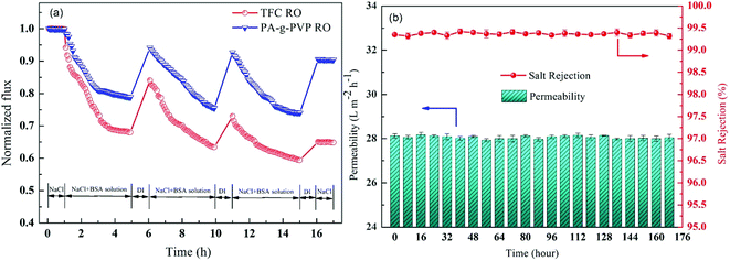 |
| | Fig. 12 (a) Effect of fouling (BSA, 100 ppm) on water fluxs of virgin membrane TFC RO and PA-g-PVP RO membrane; one-cycle “filtration-rinsing” condition: Equal initial water flux (TMP: virgin membrane TFC RO 15.0 bar, PA-g-PVP RO membrane 15.5 bar), 25.0 ± 0.5 °C, pH: 7.0. (b) Long-term cross-flow permselectivity test of the modified membrane during the 168 hour investigation. | |
Table 2 Comparison of antifouling and separating properties of RO membranes
| Starting membrane |
Modification method |
Separating properties |
Antifouling properties |
Reference |
| J (L m−2 h−1) |
R (%) |
FRR (%) |
| PA-g-TAEA |
One-step bimodel grafting via Ugi-4CR |
38.9 |
98.5 |
97.2 |
50 |
| gCN |
gCN or aCN incorporated PA |
25.1 |
98.8 |
81.9 |
16 |
| GOQD/PSf membrane |
(GOQD)-incorporated TFN |
24.7 |
98.5 |
90.0 |
51 |
| SHN |
Dip coating of PEI |
31.5 |
99.3 |
95.4 |
52 |
| Lab-made |
Preparation of MPD-terminated PEG |
38.0 |
93.0 |
92.0 |
53 |
| MCM-41 |
Porous MCM-41 silica nanoparticles (NPs) |
28.5 |
98.1 |
97.5 |
54 |
| PA-g-PVP |
Surface grafting via PVP |
28.6 |
99.5 |
97.4 |
This work |
4. Conclusions
In this work, the PVP of hydrophilic macromolecules was grafted onto the PA layer of aromatic polyamide RO membrane through the combination of ray irradiation and IP technology, and the novel PA-g-PVP RO membrane was successfully prepared. Results of ATR-FTIR, SEM, AFM and XPS analysis confirmed the successful grafting of PVP on the RO membrane surface. The effects of PVP grafting polymerization condition parameters on membrane structure and separation performance, such as grafting concentration, irradiation measurement and gas atmosphere, were investigated as well. Results showed that the surface hydrophilicity of the PA-g-PVP RO membrane was obviously enhanced, salt retention rate was improved and pollution prevention performance was increased. The improvement of membrane performance is mainly attributed to the excellent hydrophilicity of the PVP. Among all the prepared membranes, the PVP-58000-2% membrane (molecular weight: 58000, concentration: 2%, irradiation dose: 20 kGy and N2) showed the best results. When the performance of the RO membrane was tested, the PA-g-PVP RO membrane salt retention increased to 99.5% without affecting the water flux. At the same time, compared with the membrane without PVP, it shows good performance in pollution prevention. The novelty of this high-performance membrane has great potential in the field of seawater desalination and sewage treatment.
Conflicts of interest
There are no conflicts to declare.
Acknowledgements
This work was supported by the following: Heilongjiang Province Natural Science Foundation (No. QC2018070), National Natural Science Foundation of China (No. 91860120), Harbin Application Technology Research and Development Projects (Outstanding Subject Leaders Type A) (No. 2015RAXXJ028) and State Key Laboratory of Urban Water Resource and Environment (Harbin Institute Technology).
References
- C. J. Vorosmarty, P. B. McIntyre, M. O. Gessner, D. Dudgeon, A. Prusevich, P. Green, S. Glidden, S. E. Bunn, C. A. Sullivan, C. R. Liermann and P. M. Davies, Nature, 2010, 467, 555–561 CrossRef CAS PubMed.
- M. Elimelech and W. A. Phillip, Science, 2011, 333, 712–717 CrossRef CAS PubMed.
- D. Rana, Y. Kim, T. Matsuura and H. A. Arafat, J. Membr. Sci., 2011, 367, 110–118 CrossRef CAS.
- M. A. Shannon, P. W. Bohn, M. Elimelech, J. G. Georgiadis, B. J. Marinas and A. M. Mayes, Nature, 2008, 452, 301–310 CrossRef CAS PubMed.
- F. Foglia, S. Karan, M. Nania, Z. Jiang, A. E. Porter, R. Barker, A. G. Livingston and J. T. Cabral, Adv. Funct. Mater., 2017, 27, 1701738 CrossRef.
- A. F. Ismail and T. Matsuura, Desalination, 2018, 434, 2–11 CrossRef CAS.
- W. J. Lau, A. F. Ismail, N. Misdan and M. A. Kassim, Desalination, 2012, 287, 190–199 CrossRef CAS.
- S. Gholami, A. Rezvani, V. Vatanpour and J. L. Cortina, Desalination, 2018, 443, 245–255 CrossRef CAS.
- S. S. Shenvi, A. M. Isloor and A. F. Ismail, Desalination, 2015, 368, 10–26 CrossRef CAS.
- D. Li, Y. Yan and H. Wang, Prog. Polym. Sci., 2016, 61, 104–155 CrossRef CAS.
- X. Zhao, R. Zhang, Y. Liu, M. He, Y. Su, C. Gao and Z. Jiang, J. Membr. Sci., 2018, 551, 145–171 CrossRef CAS.
- G. D. Kang and Y. M. Cao, Water Res., 2012, 46, 584–600 CrossRef CAS PubMed.
- Q. L. Li, Z. H. Xu and I. Pinnau, J. Membr. Sci., 2007, 290, 173–181 CrossRef CAS.
- G. Ozaydin-Ince, A. Matin, Z. Khan, S. M. J. Zaidi and K. K. Gleason, Thin Solid Films, 2013, 539, 181–187 CrossRef CAS.
- P. Marchetti, M. F. Jimenez Solomon, G. Szekely and A. G. Livingston, Chem. Rev., 2014, 114, 10735–10806 CrossRef CAS PubMed.
- X. Gao, Y. Li, X. Yang, Y. Shang, Y. Wang, B. Gao and Z. Wang, J. Mater. Chem. A, 2017, 5, 19875–19883 RSC.
- M. Safarpour, A. Khataee and V. Vatanpour, J. Membr. Sci., 2015, 489, 43–54 CrossRef CAS.
- J. Wu, Z. Wang, W. Yan, Y. Wang, J. Wang and S. Wang, J. Membr. Sci., 2015, 496, 58–69 CrossRef CAS.
- J. Imbrogno, J. J. Keating, J. Kilduff and G. Belfort, Desalination, 2017, 401, 68–87 CrossRef CAS.
- M. Meng, F. Pellizzari, S. O. B. Boukari, N. K. Vel Leitner and B. Teychene, J. Membr. Sci., 2014, 471, 1–8 CrossRef CAS.
- J.-C. An, A. Weaver, B. Kim, A. Barkatt, D. Poster, W. N. Vreeland, J. Silverman and M. Al-Sheikhly, Polymer, 2011, 52, 5746–5755 CrossRef CAS.
- S. Kadlubowski, P. Ulanski and J. M. Rosiak, Polymer, 2012, 53, 1985–1991 CrossRef CAS.
- C. Y. Y. Tang, Y. N. Kwon and J. O. Leckie, Desalination, 2009, 242, 149–167 CrossRef CAS.
- X. Song, S. Qi, C. Y. Tang and C. Gao, J. Membr. Sci., 2017, 540, 10–18 CrossRef CAS.
- Y. Wang, Z. Wang, J. Wang and S. Wang, J. Membr. Sci., 2018, 549, 495–506 CrossRef CAS.
- F. Asempour, D. Emadzadeh, T. Matsuura and B. Kruczek, Desalination, 2018, 439, 179–187 CrossRef CAS.
- J. Xu, Z. Wang, L. Yu, J. Wang and S. Wang, J. Membr. Sci., 2013, 435, 80–91 CrossRef CAS.
- T. V. Plisko, A. S. Liubimova, A. V. Bildyukevich, A. V. Penkova, M. E. Dmitrenko, V. Y. Mikhailovskii, G. B. Melnikova, K. N. Semenov, N. V. Doroshkevich and A. I. Kuzminova, J. Membr. Sci., 2018, 551, 20–36 CrossRef CAS.
- S.-H. Park, S. J. Kwon, M. G. Shin, M. S. Park, J. S. Lee, C. H. Park, H. Park and J.-H. Lee, Desalination, 2018, 436, 28–38 CrossRef CAS.
- P. S. Singh, S. V. Joshi, J. J. Trivedi, C. V. Devmurari, A. P. Rao and P. K. Ghosh, J. Membr. Sci., 2006, 278, 19–25 CrossRef CAS.
- X. Wei, Z. Wang, Z. Zhang, J. Wang and S. Wang, J. Membr. Sci., 2010, 351, 222–233 CrossRef CAS.
- C. Tang, Y. Kwon and J. Leckie, J. Membr. Sci., 2007, 287, 146–156 CrossRef CAS.
- X. Wang, H. Ma, B. Chu and B. S. Hsiao, Desalination, 2017, 420, 91–98 CrossRef CAS.
- S.-J. Park, W.-G. Ahn, W. Choi, S.-H. Park, J. S. Lee, H. W. Jung and J.-H. Lee, J. Mater. Chem. A, 2017, 5, 6648–6655 RSC.
- Y. Hu, K. Lu, F. Yan, Y. Shi, P. Yu, S. Yu, S. Li and C. Gao, J. Membr. Sci., 2016, 501, 209–219 CrossRef CAS.
- V. Vatanpour, M. Sheydaei and M. Esmaeili, Desalination, 2017, 420, 1–11 CrossRef CAS.
- M. E. A. Ali, F. M. Hassan and X. Feng, J. Mater. Chem. A, 2016, 4, 6620–6629 RSC.
- R. Jamshidi Gohari, W. J. Lau, T. Matsuura and A. F. Ismail, J. Membr. Sci., 2013, 446, 326–331 CrossRef CAS.
- S. Mu, S. Wang, S. Liang, K. Xiao, H. Fan, B. Han, C. Liu, X. Wang and X. Huang, J. Membr. Sci., 2019, 570–571, 1–8 CrossRef CAS.
- N. K. Saha and S. V. Joshi, J. Membr. Sci., 2009, 342, 60–69 CrossRef CAS.
- T. Wang, L. Dai, Q. Zhang, A. Li and S. Zhang, J. Membr. Sci., 2013, 440, 48–57 CrossRef CAS.
- Y. C. Xu, Z. X. Wang, X. Q. Cheng, Y. C. Xiao and L. Shao, Chem.
Eng. J., 2016, 303, 555–564 CrossRef CAS.
- H.-R. Chae, J. Lee, C.-H. Lee, I.-C. Kim and P.-K. Park, J. Membr. Sci., 2015, 483, 128–135 CrossRef CAS.
- X. Wang, D. Fang, B. S. Hsiao and B. Chu, J. Membr. Sci., 2014, 469, 188–197 CrossRef CAS.
- I. J. Roh, A. R. Greenberg and V. P. Khare, Desalination, 2006, 191, 279–290 CrossRef CAS.
- W. Xie, G. M. Geise, B. D. Freeman, H.-S. Lee, G. Byun and J. E. McGrath, J. Membr. Sci., 2012, 403–404, 152–161 CrossRef CAS.
- N. Combernoux, L. Schrive, V. Labed, Y. Wyart, E. Carretier, A. Benony-Rhodier and P. Moulin, J. Membr. Sci., 2015, 480, 64–73 CrossRef CAS.
- Z. Liu, X. An, C. Dong, S. Zheng, B. Mi and Y. Hu, J. Mater. Chem. A, 2017, 5, 23190–23197 RSC.
- V. Vatanpour, M. Esmaeili and M. H. D. A. Farahani, J. Membr. Sci., 2014, 466, 70–81 CrossRef CAS.
- Y. Pan, L. Ma, S. Lin, Y. Zhang, B. Cheng and J. Meng, J. Mater. Chem. A, 2016, 4, 15945–15960 RSC.
- X. Song, Q. Zhou, T. Zhang, H. Xu and Z. Wang, J. Mater. Chem. A, 2016, 4, 16896–16905 RSC.
- H. Choi, Y. Jung, S. Han, T. Tak and Y.-N. Kwon, J. Membr. Sci., 2015, 486, 97–105 CrossRef CAS.
- A. Bera, R. M. Gol, S. Chatterjee and S. K. Jewrajka, Desalination, 2015, 360, 108–117 CrossRef CAS.
- J. Yin, E.-S. Kim, J. Yang and B. Deng, J. Membr. Sci., 2012, 423–424, 238–246 CrossRef CAS.
Footnote |
| † Electronic supplementary information (ESI) available. See DOI: 10.1039/c9ra02240f |
|
| This journal is © The Royal Society of Chemistry 2019 |
Click here to see how this site uses Cookies. View our privacy policy here. 
 Open Access Article
 This Open Access Article is licensed under a Creative Commons Attribution-Non Commercial 3.0 Unported Licence
 a,
Yongqiang Guob,
Jiaming Zhangc,
Bo Tiand,
Oukai Lina,
Yawei Liua and
Chunhua Zhang
a,
Yongqiang Guob,
Jiaming Zhangc,
Bo Tiand,
Oukai Lina,
Yawei Liua and
Chunhua Zhang