
 Open Access Article
 This Open Access Article is licensed under a Creative Commons Attribution-Non Commercial 3.0 Unported Licence
New surgical meshes with patterned nanofiber mats
Pengbi Liu ab,
Nanliang Chena,
Jinhua Jiang*a and
Xuejun Wen*bcd
ab,
Nanliang Chena,
Jinhua Jiang*a and
Xuejun Wen*bcd
aCollege of Textiles, Donghua University, Shanghai 201620, P. R. China. E-mail: jiangjinhua@dhu.edu.cn
bDepartment of Chemical and Life Science Engineering, School of Engineering, Virginia Commonwealth University, Richmond, VA 23284, USA. E-mail: xwen@vcu.edu
cBeijing Ditan Hospital, Capital Medical University, Beijing, 100015, China
dSchool of Pharmaceutical Sciences, Guangzhou Medical University, Guangzhou, 511436, China
First published on 5th June 2019
Abstract
Abdominal wall hernia repair is one of the most common general surgeries nowadays. Surgical meshes used in hernia repair indeed improved the outcomes, but complications like chronic pain or hernia recurrence partly caused by mechanical mismatch cannot be ignored. This work designed six warp-knitted polypropylene (PP) meshes and found the properties of surgical meshes could be improved to better mimic the performances of human abdominal wall by designing meshes with appropriate textile structures. Poly-caprolactone was electrospun onto newly designed PP meshes and formed a thin layer of patterned nanofiber mat. The pattern of nanofiber mats was affected by the structure of meshes. Diverse nanofiber morphology (straight aligned, straight random or spiral random pattern) and fiber diameters (50–70 nm ultra-thin nanofibers or from 330 nm to 700 nm nanofibers) were observed in different regions of a single patterned nanofiber scaffold. The addition of electrospinning nanofibers enhanced cell adherence and proliferation as compared with naked PP meshes. Cell actin filaments spread along the nanofibers and formed a morphology exactly similar with the patterned mats on day 7. Furthermore, cells on thin and aligned patterned nanofibers showed much more elongation and better orientation than that of the spiral random fibers, suggesting that cell morphology can be altered by changing the patterns of scaffolds. This study helps us in further understanding the properties of hernia repair meshes with their textile structures and the biological interactions of cells with different substrates in order to develop new biomedical scaffolds with desired properties.
1. Introduction
Nowadays, hernia repair is one of the most common general surgeries performed in the world and affects millions of people each year in America.1 Many surgical meshes have appeared ever since Usher et al. firstly used a mesh material to reinforce the hernia defect in 1950s.2 The previous reports have shown that the use of meshes indeed improved surgical outcomes.3,4 However, complications like chronic pain, infections, fistula and mechanical failures are still common after surgeries.5–7 One of the major reasons that causes these complications is the mechanical mismatch between repair materials and host tissues. Thus, the development of new material that can mimic the mechanical properties of host tissues is greatly needed.Warp-knitted surgical meshes and meshes with barriers are the widely used scaffolds in the hernia repair surgeries.8,9 While satin tricot stitch is the mostly used structure among these warp-knitted surgical meshes. As the development of surgical meshes, the relation between textile structure and the mechanical properties of surgical meshes has drawn more and more attention. In 2015, Zhu et al. has emphasized the importance of textile structures to the inflammatory reaction to the mesh and suggested that synthetic meshes knitted with monofilament and large pore exhibit advantages over that of multifilament and small pore.10 Meanwhile, many previous studies have found that meshes with large pore over 1 mm showed an improved tissue response and were considered as favorable to prevent inflammatory responses.11,12 What's more, selecting an appropriate surgical mesh is a difficult task to general surgeons today due to the various hernia sites and individual patient's actual situation. Hence, diversified surgical meshes need to be developed to solve the problem. In the current study, six polypropylene (PP) monofilament warp-knitted meshes with large pore over 1 mm and different textile structures are designed and evaluated.
Electrospun nanofibers have been used widely in biomedical field. They are similar to extracellular matrix (ECM) in morphology and can mimic the native ECM to provide cell attachment sites and to improve cell proliferation.13 Additionally, it has been observed that the microstructures of scaffolds have influences on cell adhesion, cellular orientation and cell differentiation.14 To prepare nanofibers with special microstructures, Hu et al. used photolithography to pattern the electrospun nanofiber mats,15 while Xu et al. prepared anisotropically and heterogeneously aligned patterns by using wire spring templates as electrospinning collectors.16 Herein, we plan to fabricate new patterned nanofiber mats through electrospinning poly-caprolactone (PCL) onto newly designed large pore PP meshes. Since PCL is a biodegradable material utilized in many United States Food and Drug Administration (US FDA) approved medical devices,17,18 the PP/PCL nanofiber composite meshes were prepared in order to enhance the cell attachment and growth on the meshes. Scanning electron microscope and optical microscope were used to observe the morphology of thin layer of patterned nanofiber mats. Then human dermal fibroblasts were utilized to investigate the biocompatibility of PP mesh and PP/PCL composite mesh and the cellular responses of different patterned nanofiber mats.
2. Materials and methods
2.1. Materials
PP monofilament was obtained from Shandong Xinhua Medical Device Co., LTD, China. Poly(ε-caprolactone) (PCL, Mn = 80![[thin space (1/6-em)]](https://www.rsc.org/images/entities/char_2009.gif) 000), phosphate buffered saline (PBS) tablets, glutaraldehyde and paraformaldehyde were ordered from Sigma-Aldrich (St. Louis, MO, USA). Hexafluoro-2-propanol (HFIP) was acquired from Oakwood Inc., West Columbia, SC, USA. Hank's balanced salt solution (HBSS) was obtained from Gibco, USA. Human dermal fibroblasts (HDFs) were purchased from ScienCell Research Laboratories, Inc., USA. Fibroblast Medium was obtained from Biomaterials USA (Catalog # FC-10 × 50 mL, Richmond, VA, USA). 1,1′-Dioctadecyl-3,3,3′3′-tetramethylindocarbocyanine perchlorate (DiI), LIVE/DEAD™ Reduced Biohazard Cell Viability Kit, AlexaFluor 488/546 Phalloidin and 4′-6-diamidino-2-phenylindole (DAPI) were purchased from ThermoFisher (Carlsbad, CA, USA). Alamar Blue™ reagent was obtained from VWR, USA.
000), phosphate buffered saline (PBS) tablets, glutaraldehyde and paraformaldehyde were ordered from Sigma-Aldrich (St. Louis, MO, USA). Hexafluoro-2-propanol (HFIP) was acquired from Oakwood Inc., West Columbia, SC, USA. Hank's balanced salt solution (HBSS) was obtained from Gibco, USA. Human dermal fibroblasts (HDFs) were purchased from ScienCell Research Laboratories, Inc., USA. Fibroblast Medium was obtained from Biomaterials USA (Catalog # FC-10 × 50 mL, Richmond, VA, USA). 1,1′-Dioctadecyl-3,3,3′3′-tetramethylindocarbocyanine perchlorate (DiI), LIVE/DEAD™ Reduced Biohazard Cell Viability Kit, AlexaFluor 488/546 Phalloidin and 4′-6-diamidino-2-phenylindole (DAPI) were purchased from ThermoFisher (Carlsbad, CA, USA). Alamar Blue™ reagent was obtained from VWR, USA.
2.2. Meshes knitting stitch design
All the meshes here were designed to be macroporous and light weight. Meshes were warp knitted via medical grade polypropylene monofilament with a diameter of 0.1527 mm on a raschel machine, RS4EL (Runyuan Medical Supplies Technology Co., LTD, China), gauge E12 with an electronic guide bar control system. Meshes were heat-set at 130 °C for 10 minutes before test. The knitting schemas and chain notation of newly designed meshes are presented in Table 1. A stereoscopic microscope (CH-2 NIKON, ECLIPSE E200, Japan) was used to take photos of each mesh. Mesh thickness was measured via a YG141N digital fabric thickness tester (Nantong Hongda Instrument Co., LTD, China). Each mesh was tested 10 times at different points on the fabric. While mesh density was the mesh weight per square meter measured by a FA2004A electronic balance (BS124S, Germany) (n = 5 per group). Results were reported as mean ± standard deviation (STD).| Sample | Chain notation | Large pore size (mm) | Thickness (mm) | Density (g m−2) | Knitting schemas |
|---|---|---|---|---|---|
| LLM-1 | GB1: 1-0/1-2/2-3/2-1// | 2.66 × 2.92 | 0.527 ± 0.016 | 44.74 ± 0.34 | 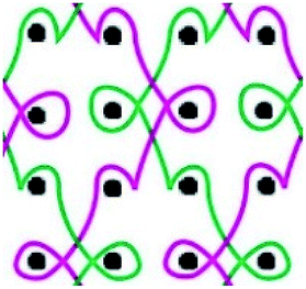 |
| GB2: 2-3/2-1/1-0/1-2// | |||||
| LLM-2 | GB1: 0-1/1-0/3-2/2-3// | 2.12 × 2.50 | 0.525 ± 0.004 | 48.85 ± 0.90 |  |
| GB2: 3-2/2-3/0-1/1-0// | |||||
| LLM-3 | GB1: 1-0/0-1/1-2/2-3/3-2/2-1// | 2.51 × 3.83 | 0.476 ± 0.008 | 39.67 ± 0.57 |  |
| GB2: 2-3/3-2/2-1/1-0/0-1/1-2// | |||||
| LLM-4 | GB1: 1-0/1-2/2-3/2-1// | 2.25 × 1.19 | 0.548 ± 0.014 | 55.88 ± 0.72 |  |
| GB2: 2-3/2-1/1-0/1-2// | |||||
| GB3: 2-2/0-0/3-3/0-0// | |||||
| LLM-5 | GB1: 1-0/0-1/1-2/2-3/3-2/2-1// | 2.45 × 3.60 | 0.667 ± 0.025 | 51.53 ± 1.39 |  |
| GB2: 2-3/3-2/2-1/1-0/0-1/1-2// | |||||
| GB3: 1-1/1-1/3-3/0-0/0-0/3-3// | |||||
| LLM-6 | GB1: 2-1/2-3/2-1/3-4/3-2/3-4// | 2.73 × 1.13 | 0.584 ± 0.004 | 63.10 ± 1.12 |  |
| GB2: 3-4/1-0/3-4/2-1/4-5/2-1// |
2.3. Fabrication of patterned PCL electrospinning mats
PCL was dissolved in HFIP (10% w/v) and stirred overnight to obtain homogenous solution. Meanwhile, to observe the morphology of patterned mats, DiI, a hydrophobic cyanine dye, was dissolved in the PCL solution at a concentration of 0.03 mg mL−1 to label the nanofibers. 13 kV high voltage was applied to a 23 G blunt tipped needle that was attached to a syringe filled with PCL solution. Newly designed meshes on a piece of aluminium foil connected to the ground electrode were used as working collectors for patterned electrospinning. The distance of needle tip to working collector was 15 cm and PCL solution was fed at a rate of 25 μL min−1 to obtain bead-free fibers. After electrospinning for 15 minutes, a thin layer of patterned PCL film was formed on the PP mesh. Patterned mats were carefully collected on thin 25 mm inner diameter 316L stainless steel rings for further studies.2.4. Surface morphology characterization
The morphology of PCL electrospun film was observed by a Field-Emission Scanning Electron Microscopy (FE-SEM, Hitachi SU-70, Japan). The patterned architecture of PCL film was observed by a microscope (OLYMPUS CKX 41, Japan). DiI loaded PCL film was investigated under a confocal laser scanning microscope (Olympus IX81, Japan).2.5. Mechanical properties evaluation
Mechanical tests of all meshes were processed as we reported previously.19 To the uniaxial tensile strength test (based on ISO/DIS 13934.1-94), samples were cut into 250 × 50 mm in the warp or weft direction. Gauge length was set as 200 mm and a pre-load of 1 N was applied. Samples were stretched at a speed of 100 mm min−1 until mechanical failure of the material.The tear resistance test was based on ISO 9073-4: 1997, Textiles – Test methods for nonwovens – Part 4: Determination of tear resistance using the trapezoidal tearing method. Samples were cut into 150 × 75 mm specimens in both directions. A 15 mm slit was cut from the midline of the 150 mm edge of the specimen. Either side of the slit was clamped in the upper or lower grip, yielding a 25 mm gauge length at the slit side and a 100 mm specimen length at the opposite side. The pre-tension was set as 1 N, then sample was tested at a strain rate of 100 mm min−1 until mechanical failure of the material.
Ball burst strength test was performed by reference to ISO 3303:1990 “Rubber-or Plastic-coated Fabric-Determination of Bursting Strength” and EN 12332-1:1998 “Rubber-or Plastic-coated Fabric-Determination of Bursting Strength – Part 1: Steel Ball Method”. Samples were cut into round shape with a diameter of 60 mm. The clamping length was set as 400 mm. The stainless-steel ball utilized here was 20 mm in diameter and burst through meshes at a speed of 100 mm min−1 until mechanical failure of the material.
Suture retention test was processed as previously described.19 Briefly, samples were cut into 50 × 50 mm along the warp or weft direction, then a high strength polyester suture was passed through the midline of the mesh and 5 mm from the edge and another polyester suture was passed through the mesh symmetrically from the opposite edge. Then one of the suture went up at a speed of 100 mm min−1 until tore out of the material.
Uniaxial tensile strength, tear resistance and ball burst strength test were performed on a HD 026N+ electronic fabric strength tester (Nantong Hongda Instrument Co., LTD, China), while the suture retention test was processed on a YG (B) 026H-500 multifunctional medical textiles strength tester (Wenzhou Darong Textile Instrument Co., LTD, China). All experiments were performed 5 times. A one-way analysis of variance (ANOVA) was performed using Minitab software (version 17), followed by Tukey's post-test. The statistical significance was set at the p < 0.05 level, and all results were reported as the mean ± STD.
2.6. Biocompatibility test
3. Results and discussion
3.1. General physical properties of six meshes
The large pore size of each sample was measured via Image J software and the largest pore diameter in weft and warp direction was recorded and shown in Table 1. Samples LLM-1, LLM-2, LLM-3 and LLM-6 were warp-knitted by two guide bars. As the knitting schemas shown, all the knitting loops of LLM-3 are open and LLM-6 are entirely consisted of closed loops, while LLM-1 and LLM-2 are comprised of equal number of open and closed knitting loops. LLM-4 and LLM-5 were knitted by three guide bars and the third guide bar was used to insert inlays into LLM-1 and LLM-3, respectively. Therefore, LLM-4 and LLM-5 were thicker and heavier than LLM-1 and LLM-3 due to the third inlays, and also the pore size of the former meshes was reduced as compared with the latter ones. But all the meshes own large pore size over 2 mm. LLM-3 exhibited the largest pore size of 2.51 × 3.83 mm and the lightest mesh here at a density of 39.67 ± 0.57 g m−2. LLM-6 was thicker and heavier than the other three two-guide bars knitted meshes mainly by reason of its special textile structure: the second guide bar has to move a longer stitch distance to form the next loop than that of the other guide bars.The newly designed meshes here are from “very thin” to “thin” in thickness as compared with the commercially available meshes.8 LLM-1, LLM-2 and LLM-3 are light weight (35–50 g m−2) and the rest three meshes here are medium weight (50–90 g m−2) in mesh density. All the meshes here are lighter than BardMesh (102.40 ± 0.8 g m−2, Davol, Inc), PROLENE (79.50 ± 1.3 g m−2, Ethicon, Inc), ProLite (85.00 ± 1.0 g m−2, Atrium Medical Corp), C-QUR Lite “Small” (69.19 ± 0.8 g m−2, Atrium Medical Corp), INFINIT Mesh (65.63 ± 1.5 g m−2, WL Gore & Associates, Inc) and other meshes.20 Therefore, these meshes are potential to use as new surgical meshes in terms of general physical properties.
Six meshes here all exhibited large pore over 2 mm, as shown in Fig. 1. The warp direction mentioned in this work is paralleled with the loop orientation and the weft is perpendicular to the loop orientation of the warp-knitted meshes.
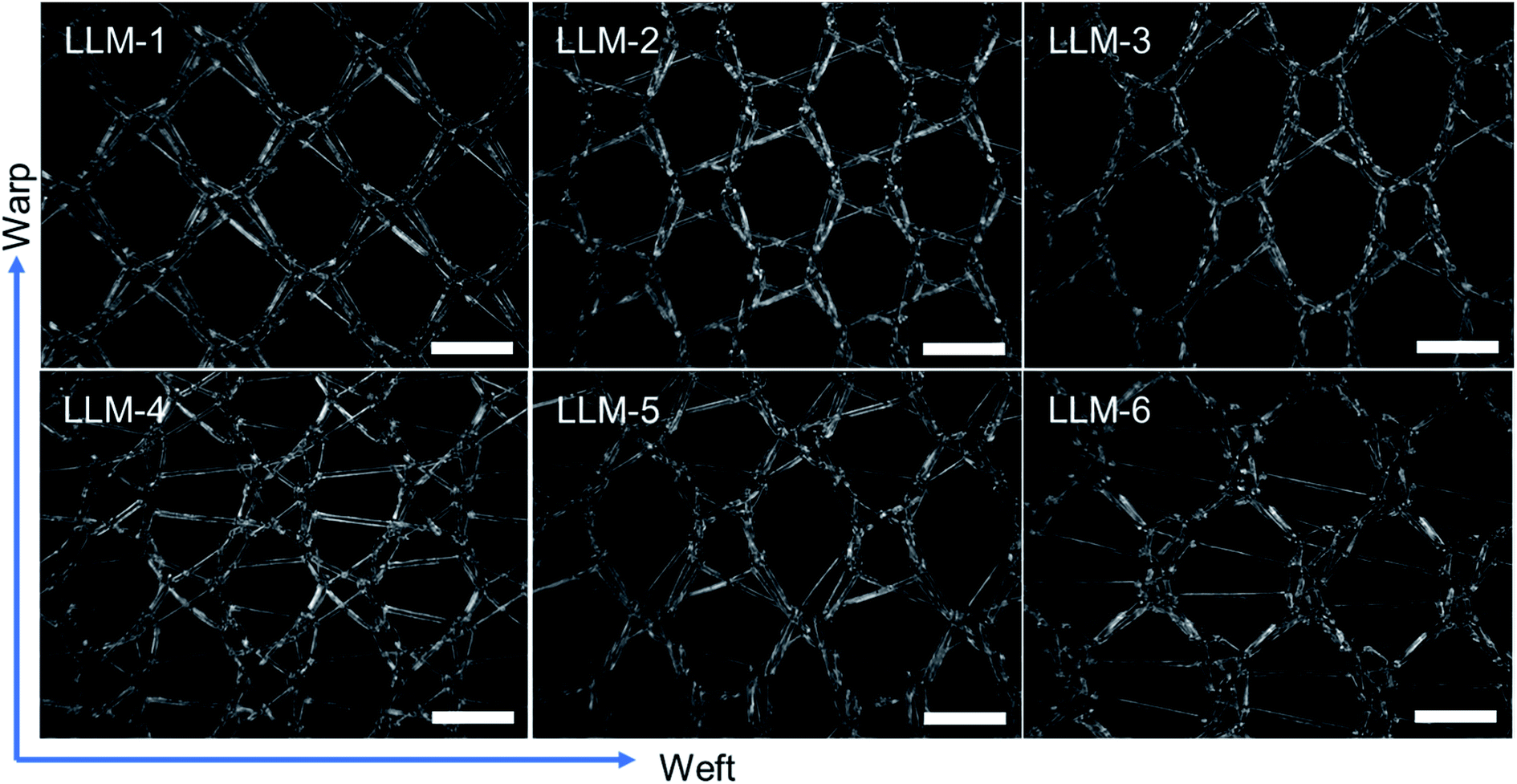 | ||
| Fig. 1 Microscopy photos of six meshes, scale bar represents 2 mm. The longitudinal direction is the warp direction of the meshes and the transverse is the weft direction. | ||
3.2. Mechanical properties of six meshes
In vitro mechanical performance is a crucial factor in a successful hernia repair. In this work, six meshes exhibited different physical–mechanical properties due to their diverse textile structures (Fig. 2). Uniaxial tensile strength is the mostly investigated character in the research of soft tissue repair scaffolds. Herein, in Fig. 2A, the warp tensile strength of LLM-4 displayed statistically significant difference with LLM-2 (P = 0.000), LLM-5 (P = 0.044) and LLM-6 (P = 0.000), but showed no statistical difference with LLM-1 and LLM-3. While the weft tensile strength of LLM-6 was markedly different with that of LLM-1 (P = 0.009), LLM-3 (P = 0.000) and LLM-5 (P = 0.000). The uniaxial tensile strength of LLM-4 was the overall strongest among these meshes at 280.2 ± 19 N in warp direction and 193.8 ± 17 N in weft direction. Since LLM-4 and LLM-5 were knitted by adding a third partly-threaded inlay guide bar in the basal structure of LLM-1 and LLM-3, they exhibited similar tensile strength with the corresponding basal meshes.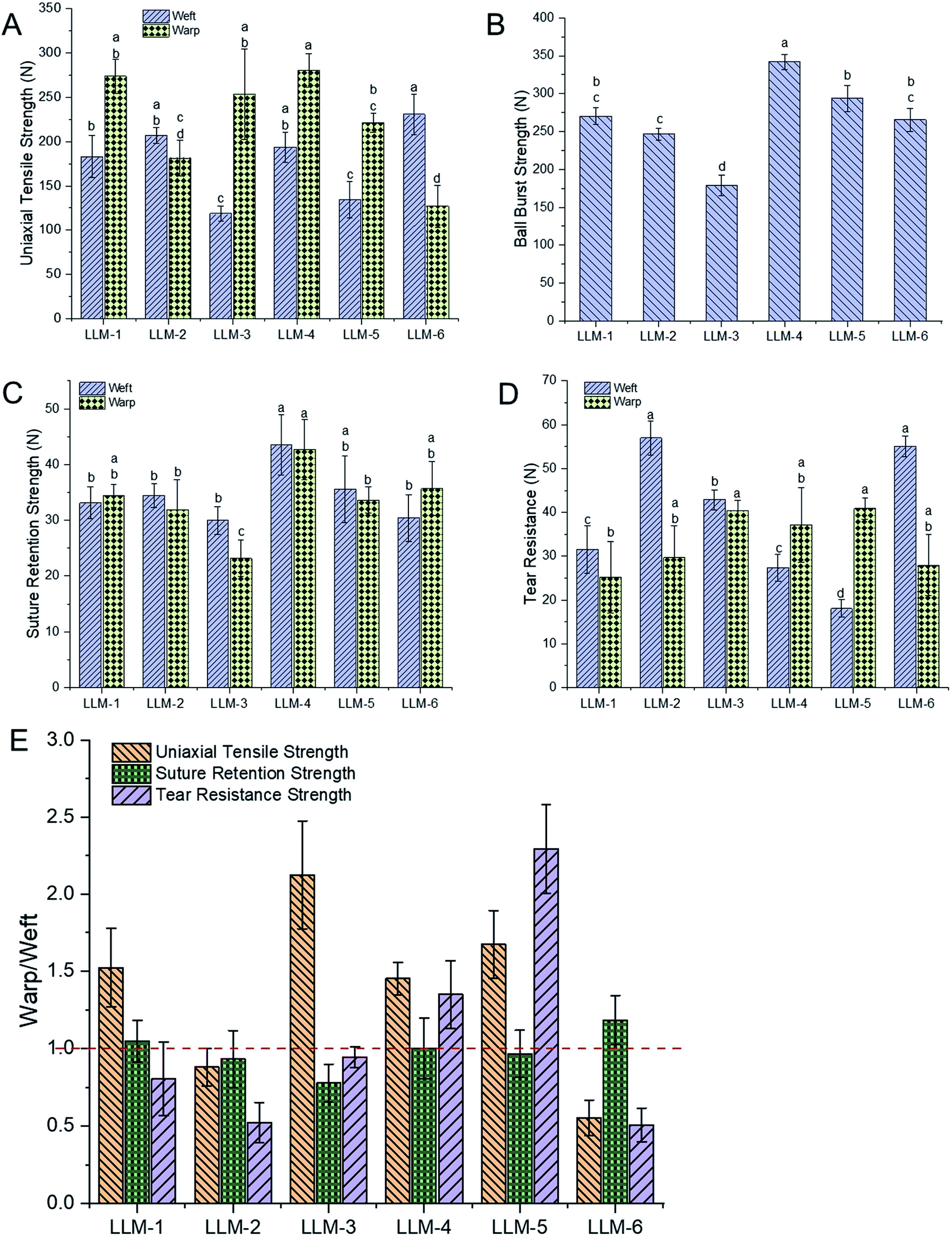 | ||
| Fig. 2 Mechanical properties of six meshes. (A) Uniaxial tensile strength, (B) ball burst strength, (C) suture retention strength, (D) tear resistance, (E) the warp and weft strength ratio of uniaxial tensile strength, suture retention strength and tear resistance strength of six samples. Different letters (a–d) in figure (A)–(D) represent statistically significant differences at P < 0.05 level. | ||
As shown in Fig. 2B and C, LLM-4 displayed the strongest ball burst strength and suture retention strength than others. While LLM-3 seemed to be not as tough as other meshes to resist ball burst and suture retention force. Other meshes were in the moderate level. In these two tests, LLM-4 and LLM-5 exhibited higher strength than LLM-1 and LLM-3 in the orthogonal directions due to the appearance of the third guide bar of inlays. While the tear resistance presented different phenomena (Fig. 2D) with the uniaxial tensile strength. LLM-6 and LLM-2 displayed similar and the overall strongest tear resistance in these meshes. The warp tear resistance of LLM-3 and LLM-5 had no significant difference with each other but were higher than that of the others.
Fig. 2E illustrates the warp to weft ratio of six meshes in uniaxial tensile strength, suture retention strength and tear resistance strength. For the uniaxial tensile strength, LLM-3 showed the highest warp to weft strength ratio at 2.13, followed by LLM-5, LLM-1 and LLM-4 at a ratio of 1.67, 1.52 and 1.45, respectively. While mesh LLM-6 and LLM-2 seemed to possess opposite properties. The tensile strength of LLM-6 in the weft direction is 1.8 times the value of the warp direction, and the transverse tensile strength of LLM-2 is slightly higher than the longitudinal direction. While to the tear resistance strength, LLM-5 was the most nonisotropic one at a warp to weft ratio of 2.29. The warp tear resistance of LLM-4 was 1.35 times the strength of the weft direction. On the contrary, the rest four samples all presented higher weft tear resistance than warp direction. Specially, the weft to warp ratio of tear resistance of LLM-6 and LLM-2 were much higher, namely 1.97 and 1.92, respectively. All samples showed a warp to weft ratio of 1 or so of suture retention strength, namely that these meshes could bear the similar suture tension force at the longitudinal and transverse directions.
In general, the addition of the third guide bar of inlays enhanced the ball burst strength and suture retention strength as compared with the basal structures. The effective number of monofilaments involved in test will directly affect the ball burst strength, while, as we can see from Fig. 1, LLM-4 displayed much more monofilaments in a repetition of weave, which probably is the reason why the ball burst strength of LLM-4 is statistically significantly higher than others. As to LLM-3, the knitting loops of it were all open loops, as shown in Table 1, which impacted the stability during the ball bursting test. The uniaxial tensile strength and tear resistance of LLM-4 were also slightly improved as compared with that of LLM-1, while this phenomenon was not found between LLM-5 and LLM-3. As shown in Fig. 1, unlike LLM-4 and LLM-6, the inlays were not uniformly distributed in LLM-5. Thus, the corresponding fibers of LLM-5 will not bear the stress as evenly as LLM-3 when stretched, and meshes will break from the weakest point, resulting in a lower strength. The knitting stitch of the third guide bar of LLM-5 can be altered to fabricate uniformly distributed meshes to improve the mechanical performances.
Overall, the mechanical properties of meshes designed here are equal or even slightly superior to that of some commercially available meshes reported in previous studies.8 Six meshes all exhibited anisotropy and LLM-5 and LLM-6 seemed to be the most anisotropic ones in these meshes. Although the addition of the third guide bar of inlays increased the thickness and mesh area density and decreased the pore size as compared with corresponding basal meshes, the mechanical performances were improved. LLM-6 possess higher mechanical properties in the weft direction than that of warp direction, while LLM-5 and LLM-4 are much stronger in the warp direction. The form of knitting loops (open or closed) and the addition of inlays or not will also affect the mechanical properties of meshes.
Human abdominal wall is consisted of many different layers with diverse mechanical properties. It is reported that the linea alba, anterior and poster or rectus sheath, umbilical and transversal is fascia are all anisotropic.21–23 What's more, the anisotropy index of different layers was also different, varying from 2.0 to 14.5, and the ultimate tensile strength of the transverse direction was found larger than that of the longitudinal direction of different human abdominal layers.20,24,25 However, the composite layers of human abdominal wall displayed different anisotropy ratio, about 1.3 to 1.4.26 Six meshes fabricated here also exhibited anisotropy at 1.25 to 2.29 (Fig. 2E), suggesting that meshes here have the potential to mimic the different individual layer or composite layers of human abdominal wall. What's more, the mesh direction with larger tensile strength should be paralleled to the transverse direction of human abdominal wall during surgeries. Different meshes with appropriate textile structures can be selected for different hernia site repairs.
3.3. Surface morphology of patterned nanofibers
PCL nanofibers were deposited onto the PP meshes on the collector and formed different patterns. As seen in Fig. 3A, there were two types of patterned nanofibers due to the difference of pore morphology of the six meshes knitted here: pore with inlays and pore without inlays. In the large pore with inlays situation (Fig. 3A(a)), most nanofibers gathered onto PP monofilament and formed a pattern exactly like the PP mesh as a collector. While to the large pore without inlays (Fig. 3A(b)), nanofibers mainly deposited on the pore area due to the higher electric potential difference than that of the monofilament region. The distribution schematics of nanofibers assembling on PP meshes were illustrated in Fig. 3A(a1) and (b1), and the patterns were hereafter referred to as LPWIP and LPP, respectively. The nanofibers assembled neighboring PP monofilaments were relatively aligned pattern, as shown in Fig. 3A(c), either loosely aligned (Fig. 3B(B1 and B3)) or densely aligned (Fig. 3B(B2)). While nanofibers assembled on the PP monofilament were random and straight pattern (Fig. 3A(d)). In the central area of large pore without inlays pattern (LPP), nanofibers appeared to be random and spiral architecture (Fig. 3A(e), B(B4) and C(C3)). While nanofibers deposited on LPWIP were almost all straight fibers, as presented in the optical microscope images Fig. 3C(C1 and C2). The average diameter of PCL nanofibers deposited on PP monofilament, near PP monofilament and in the central area of large pore were 553 nm, 391 nm and 663 nm, respectively. Ultra-thin nanofibers at a diameter of 50–70 nm were also observed nearby the monofilament regions (the red circle in Fig. 3A(c1)).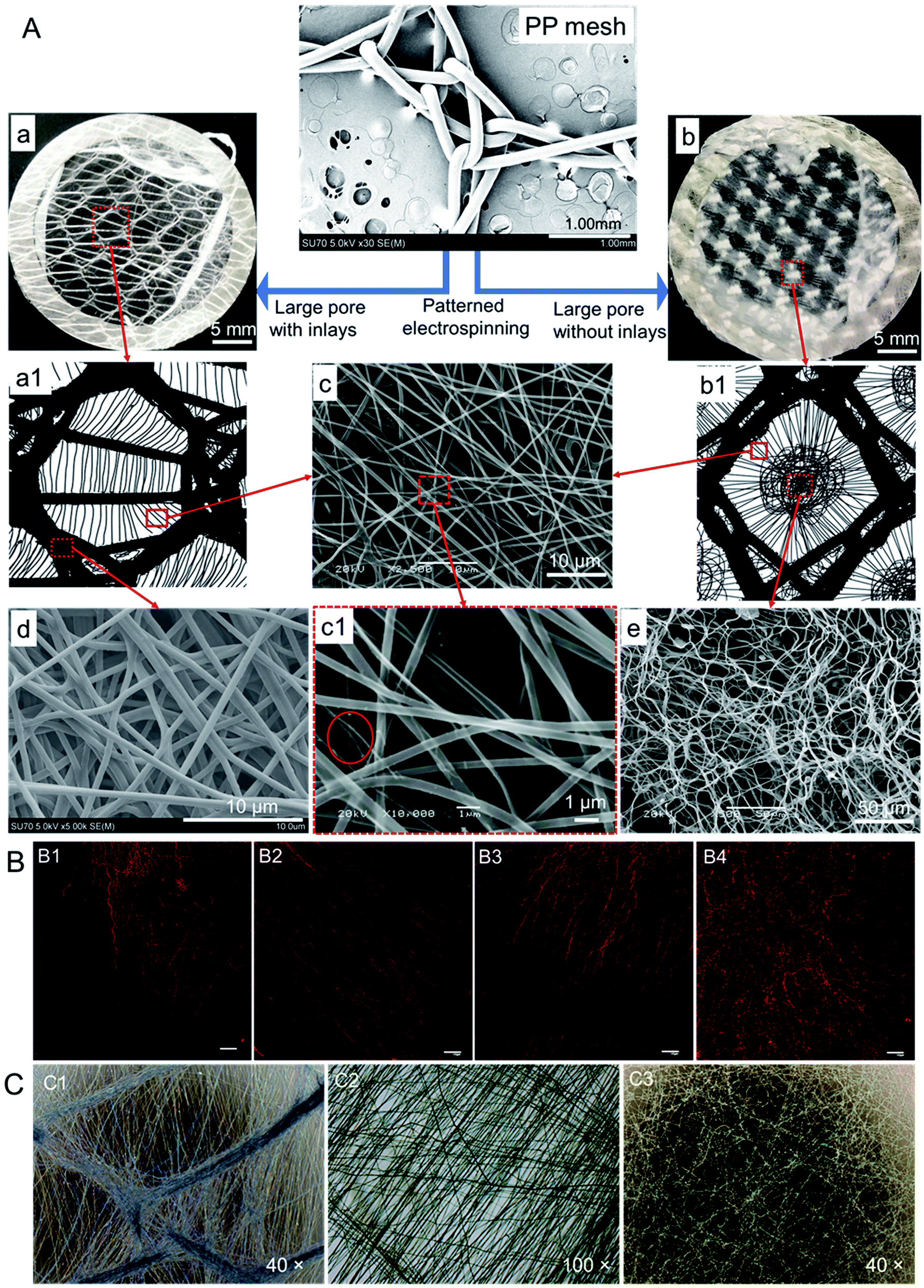 | ||
| Fig. 3 (A) Illustration and SEM photos of patterned electrospinning PCL nanofibers. Patterned architectures of PCL nanofibers are formed on mesh pore with inlays (a) and without inlays (b). (a1) and (b1) are the illustration pictures of nanofibers deposited on the PP mesh. Diverse patterns appeared on different area of mesh. (c) Relatively aligned fibers. (d) Random orientation and straight fibers. (e) Random and spiral fibers. (c1) Magnified area of panel (c), ultra-thin fibers were found here in the red circle. (B) Fluorescent images of patterned PCL nanofibers in different pattern. Loosely aligned pattern (B1) and (B3). Densely aligned pattern (B2). Random and spiral pattern (B4). PCL was dyed with DiI and scale bar represents 100 μm. (C) Patterned PCL nanofibers images photo by optical microscope. (C1) Patterned architecture formed around the knitting point of PP monofilaments. (C2) Random and straight orientation pattern. (C3) Random orientation pattern formed in the central area of large pore of meshes. | ||
Studies show that different patterned architectures can be achieved by using corresponding collectors. Zhang et al. fabricated three-dimensional fibrous tubes by electrospinning fibers onto different working collectors and patterned tubes were prepared, e.g., single tubes with multiple micropatterns, multiple interconnected tubes or tubes with different cross-section shapes.27 While Rogers and co-workers found that the microstructures of the formers have influence on the microfiber pattern. In their study, sinusoidal, sawtooth, re-entrant honeycomb and hexagonal patterned mats were fabricated successfully, and the fiber average diameters were also found different in the peak and in the valley regions within a single scaffold (saw-tooth or re-entrant honeycomb pattern).28
In the current study, patterned nanofiber sheets were prepared by electrospinning PCL nanofibers on different PP meshes designed here. Nanofibers deposited on meshes with large pore form a pattern like Fig. 3A(b), and a pattern like Fig. 3A(a) formed in the case of large pore with inlays. Random orientation and spiral-like configuration (Fig. 3B(B4)) formed in the central of large pore region and presented thicker fiber diameters than other areas. While fibers near PP monofilament turn out to be straight aligned with thinner fiber diameter than the rest. More importantly, ultrathin fibers of 50–70 nm nanofibers formed in these straight aligned fibers, which will improve cell proliferation by providing more cell attachment sites.29,30 While fibers deposited directly onto PP monofilament were straight and dense and displayed moderate fiber diameter.
As mentioned in Table 1, the large pore diameters of PP meshes in this study were over 2 mm and the thickness of them was in the range of 460 to 670 μm. Thus, the nanofibers deposited onto PP monofilament displayed larger fiber diameters than that of the nanofibers deposited near PP monofilament, just like that of the peak region and valley region in the sawtooth pattern.28 In the case of the large pore central area, the nanofibers possessed the largest fiber diameter here mainly due to the over 2 mm large pore. PP mesh was put onto aluminum foil directly and connected to the ground electrode, so the electric potential of the large pore area was lower than the PP monofilament areas, which will attract the charged fibers to deposit with priority. Herein, the electrospinning collector pattern will affect the electromagnetic field distribution and then influence the nanofiber distribution and form different patterned nanofiber mats. Many researches have figured out that the applied voltage, electrospun solution feeding rate, concentration or drop height will affect the fiber diameter or morphology,31–33 while the diverse nanofiber patterns here revealed that the electrospinning collector not only affects where the nanofibers deposit and the configuration of nanofibers, but also influences the diameters distribution of fibers. Therefore, PP meshes with appropriate textile structures can be utilized as electrospinning collectors to tailor corresponding nanofiber patterns to mimic the diverse morphology of extracellular matrix.
3.4. Biocompatibility evaluation of meshes
The in vitro biocompatibility test of composite meshes is necessary to evaluate scaffolds for biomedical application. Herein, HDFs were used to compare the difference of biocompatibility between naked PP mesh and PP/PCL composite meshes. As shown in Fig. 4A, the surface of PP or PP/PCL mesh is completely covered with cell layers on day 21, suggesting that PP and PP/PCL composite meshes were all biocompatible to HDFs. However, the number of cells on PP mesh was very low as compared to PP/PCL composite meshes on day 7. What's more, much more dead cells (stained red in the Live/Dead assay) were observed on PP mesh than the PP/PCL group. Most areas of PP monofilament were covered with HDFs on naked PP mesh and cells began to spread and fill the small pore area in monofilaments on day 14. In the case of the PP/PCL nanofiber composite meshes, most cells were found proliferated not on the monofilament but on the nanofibers on day 7. However, some cells were observed spread on the PP monofilament after 14 days culture, and cells on the nanofibers seem to be a little more aligned than that of day 7. On day 21, almost all the surface of PP monofilament or PCL nanofibers in both groups were covered with HDFs, and even the small pores in monofilaments were filled with cell actin filaments. Additionally, cells seem to proliferate quickly from day 7 to day 14 on both meshes and PP/PCL composite mesh exhibited better cell viability than naked PP mesh. This complied well with the Alamar Blue data in Fig. 4B and the cell viability difference between two groups turned out to be significantly different at each time point. Thus, PP/PCL nanofiber composite mesh improved cell proliferation at the primary stage and development stage as compared with the naked PP meshes.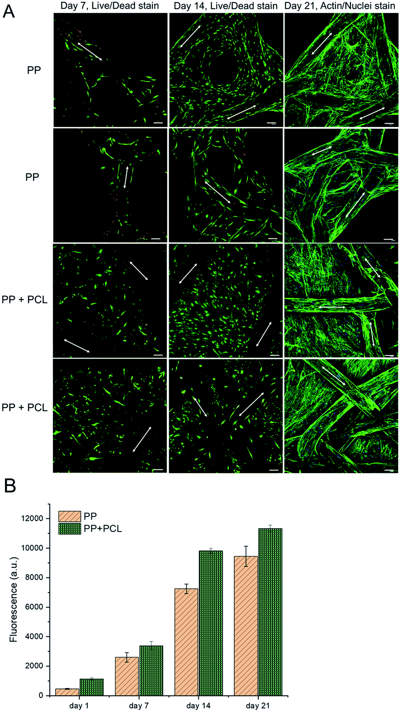 | ||
| Fig. 4 The biocompatibility of PP and PP/PCL composite meshes to HDFs. (A) HDFs morphology after grown on different meshes for 7, 14 and 21 days. On day 7 and day 14, cells were treated with Live/Dead assay and on day 21, cells actin filament and nuclei were stained with AlexaFluor 488 Phalloidin and DAPI, respectively. The white arrows indicate the PP monofilament orientation. Scale bars represent 100 μm. (B) Cell viability of HDFs on PP and PP/PCL composite meshes on days 1, 7, 14 and 21 by Alamar Blue assay. | ||
Nanofibers have been used in biomedical field widely due to the high ratio of surface area to volume,34,35 and presented good cell–materials interactions to plenty of cells.36–39 However, there is a disadvantage of nanofiber sheet applied in hernia repair, the relatively weak mechanical properties.40 Thus, we designed a new composite mesh by using newly designed PP meshes as substrate to provide mechanical support and a thin layer of biodegradable PCL nanofibers to enhance the biocompatibility. The thin layer of nanofibers was more feasible to observe cell behaviors on composite meshes. The biocompatible evaluation here proved that the electrospinning layer improved cell viability of composite meshes from the initial stage as compared with naked PP mesh. Obviously, cells proliferated on the nanostructures firstly and then spread onto PP monofilament in the condition of the presence of both materials, indicating that the microstructure of nanofibers was more suitable for cells to adhere and proliferate than that of PP meshes.
3.5. Analysis of cellular morphology on patterned nanofiber mats
Fig. 5 illustrated the morphology transformation of HDFs from 2 h to 7 days after seeding on different patterned nanofiber mats. Cells normally began to attach to nanofibers after 2 hours incubation, as shown in the optical microscopy pictures in Fig. 5A. Some cell skeletons were observed adhered to the nanofibers and began to spread in the 200 × picture in Fig. 5A. Obviously spreading and alignment of cells on the nanofibers were found after 3 days incubation (Fig. 5B). Fig. 5C and D represent cells morphology on different regions of the two patterned nanofiber mats fabricated in this study, LPWIP and LPP, respectively. | ||
| Fig. 5 HDFs morphology on patterned nanofibers. (A) Cells optical microscopy images after seeding on fibers for 2 h. (B) Optical microscopy photos of cells grow on fibers after cultured for 3 days. Fluorescent images of HDFs on patterned fibers for 7 days were captured. Cell nuclei was stained with DAPI and cell actin filament was stained with 546 (C) or 488 (D) Phalloidin. (C1) and (C2) Cell actin and nuclei morphology on different area of large pore with inlays patterned (LPWIP) film. (D1) Typical cell morphology on the loosely aligned fiber area. (D2) Cell morphology on the transition region of LPP nanofiber mats. (D3) Cells grow on the central of large pore area of LPP film. Red or green arrows indicate the nanofiber orientations. Scale bars = 100 μm. | ||
In the case of LPWIP, nanofibers were also dyed with DAPI solution and fluorescent imaged in Fig. 5C. We may figure out that cells grew evenly on different regions of patterned fiber mats but displayed different configurations. In the straight aligned fibers region (Fig. 5C(C2)), cell skeleton displayed the same orientation and alignment with the nanofibers. Likewise, in the fibers intersection region (Fig. 5C(C1)), clear similar morphology was observed between cell actin filament and patterned nanofiber sheet. In the LPP central area, cell actin filament also exhibited random orientation like the nanofibers (Fig. 5D(D3)). Cells in the loosely aligned pattern area (Fig. 5D(D1)) showed much more distinct elongation morphology than that of random and spiral pattern in the central area (Fig. 5D(D3)).
The previous study has shown that cells grow on patterned substrate displayed higher elongation than flat substrate and cells orientation would also change along with culture time.14 Herein, in the straight aligned area, cells grow along the loosely aligned nanofibers and also spread onto the neighboring fibers (Fig. 5B), and eventually form a pattern like Fig. 5D(D1)) on day 7. During this time, cells orientation also changed gradually. Additionally, cell skeletons of the aligned area (Fig. 5D(D1)) and transition area (Fig. 5D(D2)) elongated more than that of the central area (Fig. 5D(D3)). It has been found that nanofibers with thinner diameter will improve cell proliferation and cell spreading and decrease cell aggregation.41 The current study also proved that aligned nanofibers with thinner diameter increased the actin filament elongation of HDFs. Therefore, aligned fibers indeed trigger cell skeleton to spread and stretch more than the random oriented fibers, which probably caused by the difference of fiber diameters and orientations in different regions.
4. Conclusions
Six new warp knitted polypropylene meshes were designed and evaluated in this work for the potential application in hernia repair. Two patterned nanofiber mats were obtained by electrospinning 10% PCL onto newly designed meshes. The mechanical properties of six meshes are comparable to commercially available meshes and the anisotropy of them is able to mimic the properties of human abdominal wall, suggesting that these meshes are promising to use for hernia repair. The addition of inlays increased the ball burst strength and suture retention strength of basal structures. Different regions of a patterned nanofiber mat here present diverse fiber morphology and even the fiber diameters are different in a single scaffold. The in vitro biocompatibility evaluation of PP and PP/PCL composite meshes revealed that PCL nanofibers were more suitable for cells to attach and proliferate than naked PP meshes and cells covered almost all the surface of both materials after seeding for 21 days. As to the cellular response on the patterned mats, cells showed much more elongation and aligned orientation on the loosely aligned nanofibers than that of the random and spiral patterned areas. Thus, the properties of meshes or the pattern of nanofiber mats can be tailored by utilizing meshes with appropriate textile structures to mimic the human abdominal wall or the diverse morphology of extracellular matrix.Conflicts of interest
There are no conflicts of interest in this work.Acknowledgements
This work was supported by the National Key R&D Program of China, grant number 2016YFB0303300; the China Scholarship Council, grant number 201706630077, the international visiting program from Donghua University and the Alice T. and William H. Goodwin Jr. Endowment.References
- B. K. Poulose, J. Shelton, S. Phillips, D. Moore, W. Nealon, D. Penson, W. Beck and M. D. Holzman, Hernia, 2012, 16, 179–183 CrossRef CAS PubMed.
- F. C. Usher, J. Ochsner and L. L. Tuttle Jr, Am. Surg., 1958, 24, 969–974 CAS.
- E. H. T. Collaboration, Br. J. Surg., 2000, 87, 854–859 CrossRef PubMed.
- R. W. Luijendijk, W. C. Hop, V. D. T. Mp, D. C. de Lange, M. M. Braaksma, J. N. Ijzermans, R. U. Boelhouwer, B. C. de Vries, M. K. Salu and J. C. Wereldsma, N. Engl. J. Med., 2000, 343, 392 CrossRef CAS PubMed.
- T. N. Robinson, J. J. Clarke and M. D. Walsh, Surg. Endosc., 2005, 19, 1556–1560 CrossRef CAS PubMed.
- M. Basoglu, M. I. Yildirgan, I. Yilmaz, A. Balik, F. Celebi, S. S. Atamanalp, K. Y. Polat and D. Oren, Acta Chir. Belg., 2004, 104, 425–448 CrossRef CAS PubMed.
- D. Berger, M. Bientzle and A. Müller, Surg. Endosc., 2002, 16, 1720–1723 CrossRef CAS PubMed.
- C. R. Deeken, M. S. Abdo, M. M. Frisella and B. D. Matthews, J. Am. Coll. Surg., 2011, 212, 68–79 CrossRef.
- C. R. Deeken, K. M. Faucher and B. D. Matthews, Surg. Endosc., 2012, 26, 566–575 CrossRef PubMed.
- L. M. Zhu, P. Schuster and U. Klinge, World J. Gastrointest. Surg., 2015, 7, 226–236 CrossRef PubMed.
- B. Klosterhalfen and U. Klinge, J. Biomed. Mater. Res., Part B, 2013, 101, 1393–1399 CrossRef CAS PubMed.
- F. H. Greca, Z. A. Souza-Filho, A. Giovanini, M. R. Rubin, R. F. Kuenzer, F. B. Reese and L. M. Araujo, Hernia, 2008, 12, 45–49 CrossRef CAS PubMed.
- V. Beachley and X. Wen, Prog. Polym. Sci., 2010, 35, 868–892 CrossRef CAS.
- E. Huethorst, M. P. Hortigon-Vinagre, V. Zamora-Rodriguez, P. M. Reynolds, F. Burton, G. L. Smith and N. Gadegaard, ACS Biomater. Sci. Eng., 2016, 2, 2231–2239 CrossRef CAS PubMed.
- H. Hu, J. V. Buddingh, Z. Wang, B. B. Nienhause and G. Liu, J. Mater. Chem. C, 2018, 6, 808–813 RSC.
- H. Xu, H. Li, Q. Ke and J. Chang, ACS Appl. Mater. Interfaces, 2015, 7, 8706–8718 CrossRef CAS PubMed.
- D. Kai, S. S. Liow and X. J. Loh, Mater. Sci. Eng., C, 2014, 45, 659–670 CrossRef CAS PubMed.
- J. Hu, L. Tian, M. P. Prabhakaran, X. Ding and S. Ramakrishna, Polymers, 2016, 8, 54 CrossRef PubMed.
- P. Liu, H. Shao, N. Chen and J. Jiang, Fibres Text. East. Eur., 2018, 26, 79–86 CrossRef.
- C. R. Deeken and S. P. Lake, J. Mech. Behav. Biomed. Mater., 2017, 74, 411–427 CrossRef CAS PubMed.
- A. M. Rath, J. Zhang and J. P. Chevrel, Hernia, 1997, 1, 139–142 CrossRef.
- D. Gräβel, A. Prescher, S. Fitzek, D. G. V. Keyserlingk and H. Axer, J. Surg. Res., 2005, 124, 118–125 CrossRef.
- M. Kirilova, S. Stoytchev, D. Pashkouleva and V. Kavardzhikov, Medical Engineering & Physics, 2011, 33, 1–6 Search PubMed.
- A. Kureshi, P. Vaiude, S. N. Nazhat, A. Petrie and R. A. Brown, J. Biomech., 2008, 41, 3462–3468 CrossRef PubMed.
- C. Hollinsky and S. Sandberg, Clin. Biomech., 2007, 22, 88–92 CrossRef CAS.
- F. Podwojewski, M. Otténio, P. Beillas, G. Guérin, F. Turquier and D. Mitton, J. Mech. Behav. Biomed. Mater., 2014, 38, 126–133 CrossRef CAS.
- D. Zhang and J. Chang, Nano Lett., 2012, 10, 3283–3287 Search PubMed.
- C. M. Rogers, G. E. Morris, T. W. Gould, R. Bail, S. Toumpaniari, H. Harrington, J. E. Dixon, K. M. Shakesheff, J. Segal and F. R. Rose, Biofabrication, 2014, 6, 035003 CrossRef.
- A. Greiner and J. H. Wendorff, Angew. Chem., Int. Ed. Engl., 2007, 46, 5670–5703 CrossRef CAS PubMed.
- L. He, S. Liao, D. Quan, K. Ma, C. Chan, S. Ramakrishna and J. Lu, Acta Biomater., 2010, 6, 2960–2969 CrossRef CAS PubMed.
- V. Beachley and X. Wen, Mater. Sci. Eng., C, 2009, 29, 663–668 CrossRef CAS.
- N. Bhardwaj and S. C. Kundu, Biotechnol. Adv., 2010, 28, 325–347 CrossRef CAS PubMed.
- L. Liverani and A. Boccaccini, Nanomaterials, 2016, 6, 75 CrossRef.
- E. Katsanevakis, B. Whatley, V. Beachley, X. Wen and Z. Ning, J. Biomater. Tissue Eng., 2013, 3, 448–460 CrossRef CAS.
- O. Hakimi, P. A. Mouthuy, N. Zargar, E. Lostis, M. Morrey and A. Carr, Acta Biomater., 2015, 26, 124–135 CrossRef CAS.
- P. Kuppan, S. Sethuraman and U. M. Krishnan, Mater. Sci. Eng., C, 2017, 81, 191–205 CrossRef CAS PubMed.
- R. Khajavi, M. Abbasipour and A. Bahador, J. Appl. Polym. Sci., 2015, 133, 42883 Search PubMed.
- T. K. Dash and V. B. Konkimalla, Mol. Pharm., 2012, 9, 2365–2379 CrossRef CAS PubMed.
- F. Yang, R. Murugan, S. Wang and S. Ramakrishna, Biomaterials, 2005, 26, 2603–2610 CrossRef CAS PubMed.
- G. C. Ebersole, E. G. Buettmann, M. R. MacEwan, M. E. Tang, M. M. Frisella, B. D. Matthews and C. R. Deeken, Surg. Endosc., 2012, 26, 2717–2728 CrossRef PubMed.
- G. T. Christopherson, H. Song and H.-Q. Mao, Biomaterials, 2009, 30, 556–564 CrossRef CAS.
| This journal is © The Royal Society of Chemistry 2019 |