 Open Access Article
Spinel oxide CoFe2O4 grown on Ni foam as an efficient electrocatalyst for oxygen evolution reaction†
Shasha Zhua,
Jinglei Lei *a,
Yonghan Qina,
Lina Zhanga and
Lijuan Lub
aCollege of Chemistry and Chemical Engineering, Chongqing University, Chongqing 400044, China. E-mail: leijlei@163.com
bCollege of Computer Science and Technology, Chongqing University of Posts and Telecommunications, Chonqing 400065, China
First published on 30th April 2019
Abstract
The effect of the oxygen evolution reaction (OER) is important in water splitting. In this work, we develop sphere-like morphology spinel oxide CoFe2O4/NF by hydrothermal reaction and calcination, and the diameter of the spheres is about 111.1 nm. The CoFe2O4/NF catalyst exhibits excellent electrocatalytic performance with an overpotential of 273 mV at a current density of 10 mA cm−2 and a Tafel slope of 78 mV dec−1. The cycling stability of CoFe2O4/NF is remarkable, and it only increased by 5 mV at a current density of 100 mA cm−2 after 3000 cycles. Therefore, this simple method to prepare CoFe2O4/NF can enhance the OER properties of electrocatalysts, which makes CoFe2O4/NF a promising material to replace noble metal-based catalysts for the oxygen evolution reaction.
1. Introduction
Electrochemical water splitting has been considered a viable approach to produce clean hydrogen fuel through the use of renewable energy. Electrochemical water splitting consists of two half reactions: the hydrogen evolution reaction (HER) of the cathode and the oxygen evolution reaction (OER) of the anode.1–4 Due to the OER involving four-proton-coupled electron transfer and O![[double bond, length as m-dash]](https://www.rsc.org/images/entities/char_e001.gif) O band formation, the overpotential of the OER is higher than that of the HER in electrochemical water splitting, and the OER is the bottleneck of electrochemical water splitting.5–11
O band formation, the overpotential of the OER is higher than that of the HER in electrochemical water splitting, and the OER is the bottleneck of electrochemical water splitting.5–11
In order to reduce the overpotentials of the OER, efficient electrocatalysts with excellent catalytic activity and stability are needed. Noble metal-based materials like Ru- and/or Ir-based catalysts have been well-known as prominent catalysts for OER, but Ru- and/or Ir-based catalysts still require larger overpotential to deliver a current density of 10 mA cm−2. Moreover, the scarcity, high cost and poor durability seriously hamper large-scale application of noble metal-based materials.12–19
Recently, due to the low cost and earth-abundant reserves, many efforts have been made to develop high activity non-noble metal based electrocatalysts. Non-noble transition metals such as Fe, Co, Ni and Mn have attracted a lot of attention, and the compounds of transition-metals have been suggested as replaceable electrocatalysts in OER. As OER catalysts, spinel oxides, such as N-CG–CoO,20 Co3O4,21 Co3O4/N-rmGO,22 LiCoO2,23 NiFeOx,24 NiCo2O4 (ref. 25) and CoFe2O4 (ref. 26) have been widely studied as advanced electrocatalysts because of their unique crystal structure and remarkable properties. Among the various spinel oxides, CoFe2O4 is one of the most interesting compounds due to its high abundance, low cost, low toxicity, rich redox chemistry and high electrochemical activity. There are a few reports on the research of CoFe2O4 as an OER electrocatalyst.27,28 Zhang et al. reported CoFe2O4 nanofibers which were prepared by electrospinning technique with an overpotential of 340 mV to deliver a current density of 10 mA cm−2 in 1.0 M KOH.26 Ding et al. prepared CoFe2O4/SWNTs nanorods via hydrothermal method and compound with SWNTs by sonication, which required an overpotential of 310 mV to achieve a current density of 10 mA cm−2 in 1.0 M KOH.28 The CoFe2O4/biomass carbon hybrid catalyst has been synthesized from sulfate reducing bacteria via enrichment of Co with porous structure and rough surfaces, and required 300 mV for generating the current density of 10 mA cm−2 in 1.0 M KOH.27 Although many advances have been made, the electrical conductivity and surface area are low, resulting in poor catalytic performance, and the catalytic performances need to be improved.29
In general, to ensure the electrocatalyst working at high electrochemical activity, the catalyst is usually attached to a conducting surface to ensure fast electron transport. The nickel foam (NF) has conductive surface with three-dimensional (3D) porous structure, and such 3D architecture is beneficial for increasing the number of reaction sites.30,31 In this work we design sphere-like morphology spinel oxide CoFe2O4 grown on Ni foam (NF) through hydrothermal and calcination method using urea, iron chloride tetrahydrate, cobalt nitrate hexahydrate and sodium chloride. During the process of hydrothermal, the sodium chloride not only acts as crystal template but also adjusts the morphology of the catalyst. The electrode has excellent electrochemical conductivity, small charge transfer resistance, large active surface area and outstanding stability.
2. Experimental
2.1 Chemicals
Ferrous chloride tetrahydrate (FeCl2·4H2O, >99.7%) was obtained from Chemical Reagent factory of Tianjin. Cobalt nitrate hexahydrate (Co(NO3)2·6H2O, >98.5%), sodium chloride (NaCl, >99.5%) and urea (CO(NH2)2, >99.0%) were provided by Chemical Reagent factory of Chengdu Kelong. Ni foams (99.99% purity, 1.0 mm thickness, 110 PPI pore size) were purchased from Lifeixin Metal Co. Ltd. All the reagents were analytical grade and used without further purification.2.2 Catalyst synthesis
The CoFe2O4/NF catalyst was synthesized by hydrothermal reaction and annealing treatment. Typically, NF (1 cm × 1 cm) was cleaned by sonication in acetone, 3.0 M HCl and ethanol for 5 min each to remove the surface oxide layer, the pre-cleaned NF was transferred into 30 mL of the mixture solution containing 0.5 mmol Co(NO3)2·6H2O, 1.0 mmol FeCl2·4H2O, 3.0 mmol CO(NH2)2 and 3.0 mmol NaCl for 6 h at 120 °C. After hydrothermal reaction, rinsed the NF with distilled water and absolute ethanol to remove the residual reactants, and dried in vacuum oven for overnight. Finally, the NF was put into quartz boat, and the NF was annealed to 300 °C at 5 °C min−1 in static argon environment for 1 h. For the comparison, the CoOx/NF and FeOx/NF were prepared by the same procedure without FeCl2·4H2O and Co(NO3)2·6H2O.2.3 Catalysts characterization
The morphology and elemental mapping distribution of the samples were examined using a field-emission scanning electron microscope (FESEM) equipped with an energy dispersive spectrometer (EDS) (JEOL JSM-7800F, Japan). The phase composition of the samples was identified by using an X-ray diffractometer (XRD, X'pert PRO, PANalytical B.V., Holland) using Cu Kα radiation (0.15418 nm). The chemical composition of the sample was analyzed by X-ray photoelectron spectroscopy (XPS, Thermo electron ESCALAB250, USA) using Al Kα radiation.2.4 Electrode preparation and electrochemical characterization
The measurement of electrochemical impedance spectroscopy was tested at 25 °C in a standard three-electrode system connected to an autolab (PGSTAT302N) electrochemical workstation, and other electrochemical measurements were performed with the three-electrode system using a CHI760B electrochemical workstation at 25 °C. The three-electrode system includes a sample coated on Ni foam as the working electrode, a graphite plate as the counter electrode and an Hg/HgO electrode as the reference electrode, respectively. Electrolyte of 1.0 M KOH aqueous solution was saturated with oxygen bubbles at least 30 min prior to experiment, and OER polarization curves were obtained by linear sweep voltammetry (LSV) with a scan rate of 5 mV s−1. The resistance R was tested by electrochemical impedance spectroscopy (EIS). EIS measurements were carried out in the configuration from the frequency range of 105 to 0.1 Hz, and conducted under oxygen evolution voltage, which corresponds to the potential at 10 mA cm−2. The stability test was performed by the cyclic voltammetry (CV) method with a scan rate of 40 mV s−1.3. Results and discussion
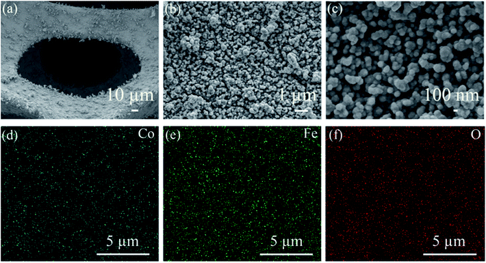
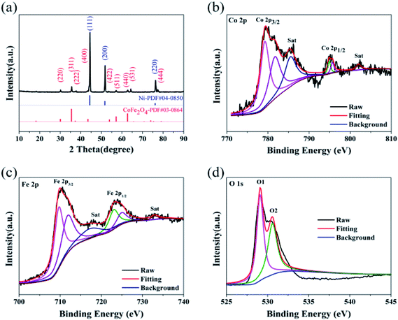
The crystal structure of CoFe2O4/NF was investigated by XRD, as shows in Fig. 1a. Selected area electron diffraction pattern at 44.507°, 51.846° and 76.370° reflect of NF to (111), (200) and (220) diffraction lattice faces, respectively. The prominent peaks at 30.0°, 35.4°, 37.3°, 43.5°, 53.9°, 57.2°, 62.7°, 65.7° and 77.8° are defined as the (220), (311), (222), (400), (422), (511), (440), (531) and (444) diffraction lattice faces, respectively, which are in good accordance with the standard patterns of CoFe2O4/NF.32–35 X-ray photoelectron spectroscopy (XPS) was performed to classify the elemental compositions and chemical valences of CoFe2O4/NF (Fig. 1b–d). Fig. 1b displays the Co 2p3/2, Co 2p1/2 and satellite peaks for Co3+ (779.3 and 794.8 eV), Co2+ (781.6 and 794.8 eV) and satellite features (785.5 and 802.1 eV).36,37 The peaks originated at 709.7, 711.8, 722.9 and 724.9 eV are attributed to Fe2+ 2p3/2, Fe3+ 2p3/2, Fe2+ 2p1/2 and Fe3+ 2p1/2 states, respectively (Fig. 1c).38,39 Fig. 1d shows the high resolution O 1s spectrum, and the O 1s spectrum in Fig. 1d exhibited two peaks at 529.1 and 530.6 eV, which due to the metal–oxygen bonds and oxygen in the hydroxyl group on the outside of catalyst.40–42 The XRD and XPS test results confirmed that the main component of the catalyst is the spinel oxide CoFe2O4.The morphology of CoFe2O4/NF characterized by SEM. Fig. 2a shows that CoFe2O4/NF also retained the NF framework morphology, and the catalytic material of CoFe2O4/NF was uniformly grown on the surface of NF substrate (Fig. 2b). Fig. 2c revealed that the catalyst of CoFe2O4/NF displayed sphere-like structure. The sphere and sphere closely connected to more ideal sphere-like crystals of CoFe2O4/NF, and the diameter of the sphere is about 111.1 nm. The images of CoFe2O4/NF precursors were shown in Fig. S1 (ESI, ESI†). The morphology of precursor is the same as CoFe2O4/NF catalyst, which confirms that only the composition of the final catalyst is changed and the morphology don't change after calcination. During the formation of the spherical structure of the catalyst, NaCl acts as crystal template and plays a role in regulating the morphology. Using NaCl as crystal template has the following advantages: (i) it is one of the most soluble salts in water; (ii) the high melting point of NaCl ensures that the template does not collapse during calcination; (iii) NaCl is the most abundant salt on earth.43–45 The carbonate and hydroxyl anions are provided by the hydrolysis of urea, which have an important effect on the anisotropy growth of the catalyst crystals.46 The elemental maps of CoFe2O4/NF were shown in Fig. 2d–f. The Fe, Co and O elements uniformly decorated with the NF substrate, which means that the catalyst of CoFe2O4/NF is successfully prepared and uniformly grown on the NF substrate.
 | ||
| Fig. 2 (a)–(c) FESEM images of CoFe2O4/NF at different magnifications. (d)–(f) The elemental mapping of the CoFe2O4/NF. | ||
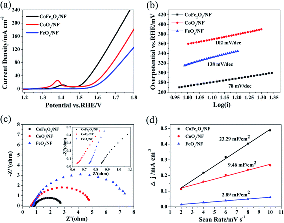
The OER performances of CoFe2O4/NF, CoOx/NF and FeOx/NF were assessed in 1.0 M KOH (Fig. 3a). The overpotentials at 10, 50 and 100 mA cm−2 for CoFe2O4/NF are 273, 341 and 400 mV, respectively, while the overpotentials of CoOx/NF (FeOx/NF) are 317 (360) mV, 413 (449) mV and 478 (529) mV at the current density of 10, 50 and 100 mA cm−2, respectively (Table S1†).These results demonstrate that the CoFe2O4/NF is superior to CoOx/NF and FeOx/NF in activity. The Tafel slope for CoFe2O4/NF is 78 mV dec−1, which is smaller than that of CoOx/NF (102 mV dec−1) and FeOx/NF (138 mV dec−1), indicating that CoFe2O4/NF has a more favorable OER kinetics.47 To investigate the kinetics leading to the catalytic enhance, electrochemical impedance spectroscopy (EIS) was used. Fig. 3c shows that the charge transfer resistance (Rct) values of the CoFe2O4/NF, CoOx/NF and FeOx/NF are estimated to be 2.08, 4.49 and 7.24 Ω from the diameter of semicircle, respectively, so the CoFe2O4/NF catalyst has smaller Rct than CoOx/NF and FeOx/NF, and the CoFe2O4/NF catalyst has rapider reaction rate during the catalytic process.48 Fig. 3d shows the double-layer capacitance (Cdl) to evaluate the ECSA. The Cdl is obtained by CV measurement, and CV measurement is recorded at different scan rates: from 2 mV s−1 to 10 mV s−1 (Fig. S2†). The Cdl value of CoFe2O4/NF (23.29 mF cm−2) is much higher than those of CoOx/NF (9.46 mF cm−2) and FeOx/NF (2.89 mF cm−2), indicating that CoFe2O4/NF own much higher ECSA than CoOx/NF and FeOx/NF.49 The OER catalytic performance of CoFe2O4/NF is compared with reported CoFe2O4 catalysts, as in Table S2.†
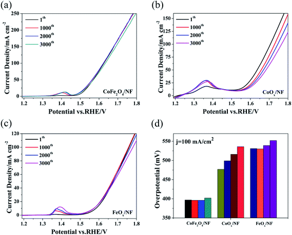
The test method for cycling stability is CV with the scan rate of 40 mV s−1 for 3000 cycles, and Fig. 3a–c show the OER polarization curves of CoFe2O4/NF, CoOx/NF and FeOx/NF at different sweeping cycles. The overpotential of CoFe2O4/NF was mostly retained up to 3000 cycles, and the overpotential of CoFe2O4/NF at the current density of 100 mA cm−2 only increased 5 mV after cycling for 3000 cycles. However, the overpotential of CoOx/NF and FeOx/NF investigation of cycling stability is further proved that the catalyst increased 21 and 16 mV at the current density of 100 mA cm−2, respectively. The CoFe2O4/NF has excellent stability.50–52 The superior OER performance of CoFe2O4/NF can be explained to the following factors: (i) the sphere morphology of CoFe2O4/NF can expose rich edge active sites; (ii) the binder-free catalyst and beneficial contacts between CoFe2O4/NF and NF can provide low resistance pathways for electrons (Fig. 4).
 | ||
| Fig. 4 The cycling stability of catalysts CoFe2O4/NF (a), CoOx/NF (b) and FeOx/NF (c), (d) for the above polarization curve, the corresponding overpotential of 100.00 mA cm−2. | ||
4. Conclusions
In this work, spinel oxide CoFe2O4 was successfully prepared on NF substrate by hydrothermal reaction and calcination. In the process of hydrothermal, NaCl not only acts as crystal template but also plays a role in regulating the morphology, and the addition of urea is beneficial to the anisotropic growth of the catalyst crystal. The morphology of CoFe2O4 on NF substrate is sphere-like, and the diameter of the sphere is about 111.1 nm. Electrochemical tests showed that CoFe2O4/NF has excellent catalytic activity toward OER, and CoFe2O4/NF catalyst delivered current density of 10 mA cm−2 at overpotential of 273 mV. Moreover, the catalyst of CoFe2O4/NF has outstanding cycling stability and the overpotential of the CoFe2O4/NF at the high current density of 100 mA cm−2 almost stable after 3000 cycles CV stability test. As a result, the CoFe2O4/NF catalyst showed improved OER performance due to the decreased charge transfer resistance and increased number of active sites to the reference sample. These results make CoFe2O4/NF a promising material to replace noble metal-based catalysts for OER.Conflicts of interest
There are no conflicts to declare.Acknowledgements
This study was supported by the Project No. CDJXS11221171 supported by the Fundamental Research Funds for the Central Universities, and the sharing fund of Chongqing University's Large-scale Equipment. We also thank Dr Jianxin He for improving the analysis of X-ray photoelectron spectroscopy. We would also like to acknowledge the reviewers and editor for helpful feedback and ideas for improving the quality of our manuscript.References
- Y. Li, L. Hu, W. Zheng, X. Peng, M. Liu, P. K. Chu and L. Y. S. Lee, Nano Energy, 2018, 52, 360–368 CrossRef CAS.
- Y. Liu, X. Liang, L. Gu, Y. Zhang, G.-D. Li, X. Zou and J.-S. Chen, Nat. Commun., 2018, 9, 2609 CrossRef PubMed.
- A. Pirkarami, S. Rasouli and E. Ghasemi, Appl. Catal., B, 2019, 241, 28–40 CrossRef CAS.
- J.-T. Ren, G.-G. Yuan, C.-C. Weng, L. Chen and Z.-Y. Yuan, Nanoscale, 2018, 10, 10620–10628 RSC.
- S. Shit, S. Chhetri, W. Jang, N. C. Murmu, H. Koo, P. Samanta and T. Kuila, ACS Appl. Mater. Interfaces, 2018, 10, 27712–27722 CrossRef CAS PubMed.
- Y. Teng, X.-D. Wang, J.-F. Liao, W.-G. Li, H.-Y. Chen, Y.-J. Dong and D.-B. Kuang, Adv. Funct. Mater., 2018, 28, 1802463 CrossRef.
- H. Wu, T. Yang, Y. Du, L. Shen and G. W. Ho, Adv. Mater., 2018, 30, 1804341 CrossRef PubMed.
- W. Xi, G. Yan, Z. Lang, Y. Ma, H. Tan, H. Zhu, Y. Wang and Y. Li, Small, 2018, 14, 1802204 CrossRef PubMed.
- H. Xu, B. Wang, C. Shan, P. Xi, W. Liu and Y. Tang, ACS Appl. Mater. Interfaces, 2018, 10, 6336–6345 CrossRef CAS PubMed.
- D. Zhong, L. Zhang, C. Li, D. Li, C. Wei, Q. Zhao, J. Li and J. Gong, J. Mater. Chem. A, 2018, 6, 16810–16817 RSC.
- Z. Ma, H. Fu, C. Gu, Y. Huang, S. Hu, Q. Li and H. Wang, RSC Adv., 2018, 8, 28209–28215 RSC.
- F. Jing, Q. Lv, J. Xiao, Q. Wang and S. Wang, J. Mater. Chem. A, 2018, 6, 14207–14214 RSC.
- V. R. Jothi, R. Bose, H. Rajan, C. Jung and S. C. Yi, Adv. Energy Mater., 2018, 8, 1802615 CrossRef.
- Y. Li, F.-M. Li, X.-Y. Meng, X.-R. Wu, S.-N. Li and Y. Chen, Nano Energy, 2018, 54, 238–250 CrossRef CAS.
- G. Ren, Q. Hao, J. Mao, L. Liang, H. Liu, C. Liu and J. Zhang, Nanoscale, 2018, 10, 17347–17353 RSC.
- X. Wang, W. Ma, C. Ding, Z. Xu, H. Wang, X. Zong and C. Li, ACS Catal., 2018, 8, 9926–9935 CrossRef CAS.
- Z. Zhang, X. Ma and J. Tang, J. Mater. Chem. A, 2018, 6, 12361–12369 RSC.
- X. Zheng, Y. Zhang, H. Liu, D. Fu, J. Chen, J. Wang, C. Zhong, Y. Deng, X. Han and W. Hu, Small, 2018, 14, 1803666 CrossRef PubMed.
- J. Wang, L. Li, L. Meng, L. Wang, Y. Liu, W. Li, W. Sun and G. Li, RSC Adv., 2018, 8, 35131–35138 RSC.
- S. Mao, Z. Wen, T. Huang, Y. Hou and J. Chen, Energy Environ. Sci., 2014, 7, 609–616 RSC.
- J. Zhao, Y. He, Z. Chen, X. Zheng, X. Han, D. Rao, C. Zhong, W. Hu and Y. Deng, ACS Appl. Mater. Interfaces, 2019, 11, 4915–4921 CrossRef CAS PubMed.
- Y. Liang, Y. Li, H. Wang, J. Zhou, J. Wang, T. Regier and H. Dai, Nat. Mater., 2011, 10, 780–786 CrossRef CAS PubMed.
- T. Maiyalagan, K. A. Jarvis, S. Therese, P. J. Ferreira and A. Manthiram, Nat. Commun., 2014, 5, 3949 CrossRef CAS PubMed.
- C. C. L. McCrory, S. Jung, J. C. Peters and T. F. Jaramillo, J. Am. Chem. Soc., 2013, 135, 16977–16987 CrossRef CAS PubMed.
- W. Q. Zaman, W. Sun, M. Tariq, Z. Zhou, U. Farooq, Z. Abbas, L. Cao and J. Yang, Appl. Catal., B, 2019, 244, 295–302 CrossRef CAS.
- Z. Zhang, J. Zhang, T. Wang, Z. Li, G. Yang, H. Bian, J. Li and D. Gao, RSC Adv., 2018, 8, 5338–5343 RSC.
- S. Bi, J. Li, Q. Zhong, C. Chen, Q. Zhang and Y. Yao, RSC Adv., 2018, 8, 22799–22805 RSC.
- Y. Ding, J. Zhao, W. Zhang, J. Zhang, X. Chen, F. Yang and X. Zhang, ACS Appl. Energy Mater., 2018, 2, 1026–1032 CrossRef.
- H. Xu, J. Wei, M. Zhang, C. Liu, Y. Shiraishi, C. Wang and Y. Du, Nanoscale, 2018, 10, 18468–18472 RSC.
- Y. Li, S. Yang, H. Li, G. Li, M. Li, L. Shen, Z. Yang and A. Zhou, Colloids Surf., A, 2016, 506, 694–702 CrossRef CAS.
- J. Liang, Y. Wang, C. Wang and S. Lu, J. Mater. Chem. A, 2016, 4, 9797–9806 RSC.
- W. Bian, Z. Yang, P. Strasser and R. Yang, J. Power Sources, 2014, 250, 196–203 CrossRef CAS.
- S. Li, S. Sirisomboonchai, A. Yoshida, X. An, X. Hao, A. Abudula and G. Guan, J. Mater. Chem. A, 2018, 6, 19221–19230 RSC.
- Y. Xu, W. Bian, J. Wu, J.-H. Tian and R. Yang, Electrochim. Acta, 2015, 151, 276–283 CrossRef CAS.
- W. Yan, W. Bian, C. Jin, J.-H. Tian and R. Yang, Electrochim. Acta, 2015, 177, 65–72 CrossRef CAS.
- C. Mahala, M. D. Sharma and M. Basu, Electrochim. Acta, 2018, 273, 462–473 CrossRef CAS.
- Y. Niu, X. Huang, L. Zhao, W. Hu and C. M. Li, ACS Sustainable Chem. Eng., 2018, 6, 3556–3564 CrossRef CAS.
- Y. Wang, Q. Liu, T. Hu, L. Zhang and Y. Deng, Appl. Surf. Sci., 2017, 403, 51–56 CrossRef CAS.
- Y. Wang, Q. Liu, L. Zhang, T. Hu, W. Liu, N. Liu, F. Du, Q. Li and Y. Wang, Int. J. Hydrogen Energy, 2016, 41, 22547–22553 CrossRef CAS.
- W. Yan, X. Cao, J. Tian, C. Jin, K. Ke and R. Yang, Carbon, 2016, 99, 195–202 CrossRef CAS.
- T. Zhang, Z. Li, L. Wang, Z. Zhang and S. Wang, Int. J. Hydrogen Energy, 2019, 44, 1610–1619 CrossRef CAS.
- S. C. Sekhar, G. Nagaraju and J. S. Yu, Nano Energy, 2018, 48, 81–92 CrossRef.
- S. Xiong, J. S. Chen, X. W. Lou and H. C. Zeng, Adv. Funct. Mater., 2012, 22, 861–871 CrossRef CAS.
- W. Wang, W. Chen, P. Miao, J. Luo, Z. Wei and S. Chen, ACS Catal., 2017, 7, 6144–6149 CrossRef CAS.
- G. Fu, Z. Liu, J. Zhang, J. Wu, L. Xu, D. Sun, J. Zhang, Y. Tang and P. Chen, Nano Res., 2016, 9, 2110–2122 CrossRef CAS.
- B. Wang, T. Zhu, H. Wu, R. Xu, J. Chen and X. Lou, Nanoscale, 2012, 4, 2145–2149 RSC.
- Z.-Q. Jiang, Y.-F. Li, X.-J. Zhu, J. Lu, L. Zhang and T. Wen, RSC Adv., 2018, 8, 38562–38565 RSC.
- T. G. Novak, O. Prakash, A. P. Tiwari and S. Jeon, RSC Adv., 2019, 9, 234–239 RSC.
- F. Wang, J. Zhao, W. Tian, Z. Hu, X. Lv, H. Zhang, H. Yue, Y. Zhang, J. Ji and W. Jiang, RSC Adv., 2019, 9, 1562–1569 RSC.
- H. Lin, N. Liu, Z. Shi, Y. Guo, Y. Tang and Q. Gao, Adv. Funct. Mater., 2016, 26, 5590–5598 CrossRef CAS.
- P. S. Toth, M. Velicky, M. A. Bissett, T. J. Slater, N. Savjani, A. K. Rabiu, A. M. Rakowski, J. R. Brent, S. J. Haigh, P. O'Brien and R. A. W. Dryfe, Adv. Mater., 2016, 28, 8256–8264 CrossRef CAS PubMed.
- Y. Guo, L. Gan, C. Shang, E. Wang and J. Wang, Adv. Funct. Mater., 2017, 27, 1602699 CrossRef.
Footnote |
| † Electronic supplementary information (ESI) available: Additional experimental, additional FESEM images, cyclic voltammograms and tables. See DOI: 10.1039/c9ra01802f |
| This journal is © The Royal Society of Chemistry 2019 |


