
 Open Access Article
 This Open Access Article is licensed under a
 Creative Commons Attribution 3.0 Unported Licence
Cellulose nanofibrils prepared by gentle drying methods reveal the limits of helium ion microscopy imaging
Annika E. Ketola a,
Miika Leppänenb,
Tuomas Turpeinena,
Petri Papponenb,
Anders Strandc,
Anna Sundbergc,
Kai Arstilab and
Elias Retulainen*a
a,
Miika Leppänenb,
Tuomas Turpeinena,
Petri Papponenb,
Anders Strandc,
Anna Sundbergc,
Kai Arstilab and
Elias Retulainen*a
aVTT Technical Research Centre of Finland Ltd, P. O. Box 1603, FI-40101 Jyväskylä, Finland. E-mail: elias.retulainen@vtt.fi
bUniversity of Jyväskylä, Nanoscience Centre, Department of Physics and Department of Biological and Environmental Science, FI-40014 Jyväskylä, Finland
cÅbo Akademi University, Johan Gadolin Process Chemistry Centre, Porthansgatan 3, FI-20500 Åbo/Turku, Finland
First published on 20th May 2019
Abstract
TEMPO-oxidized cellulose nanofibrils (TCNFs) have unique properties, which can be utilised in many application fields from printed electronics to packaging. Visual characterisation of TCNFs has been commonly performed using Scanning Electron Microscopy (SEM). However, a novel imaging technique, Helium Ion Microscopy (HIM), offers benefits over SEM, including higher resolution and the possibility of imaging non-conductive samples uncoated. HIM has not been widely utilized so far, and in this study the capability of HIM for imaging of TCNFs was evaluated. Freeze drying and critical point drying (CPD) techniques were applied to preserve the open fibril structure of the gel-like TCNFs. Both drying methods worked well, but CPD performed better resulting in the specific surface area of 386 m2 g−1 when compared to 172 m2 g−1 and 42 m2 g−1 of freeze dried samples frozen in propane and nitrogen, respectively. HIM imaging of TCNFs was successful but high magnification imaging was challenging because the ion beam tended to degrade the TCNFs. The effect of the imaging parameters on the degradation was studied and an ion dose as low as 0.9 ion per nm2 was required to prevent the damage. This study points out the differences between the gentle drying methods of TCNFs and demonstrates beam damage during imaging like none previously reported with HIM. The results can be utilized in future studies of cellulose or other biological materials as there is a growing interest for both the HIM technique and bio-based materials.
1 Introduction
Cellulose nanofibrils (CNFs) have been under intensive investigation due to their unique properties, such as high tensile strength, large specific surface area, rheology and tendency for film formation.1 CNFs can be prepared from natural cellulose wood fibres by mechanical and chemical treatments,2 which makes them a biodegradable and renewable material. Various different application fields exist for CNFs ranging from paper, composites and food additives to bio-film material for printed electronics or packaging, biomedical applications and aerogels.3–8 Thus, proper characterisation of CNFs is important for quality control and safety assessment.9 The nanoscale size, the branched fibril structure and the high water content make the characterisation of CNFs challenging and demand sophisticated techniques. Scanning electron microscopy (SEM) is often used for characterisation of the morphology of CNFs and fibril dimensions in the mm to nm scale.9–13 Transmission electron microscopy (TEM) is the most powerful imaging technique and can be utilized for detailed nanoscale evaluation of single fibril dimensions of CNFs.9,14–17 SEM usually requires a conductive coating before imaging and the TEM method is limited to thin samples like single fibrils, and because of that, the new imaging method scanning helium ion microscopy (HIM) has aroused interest during recent years.In the HIM method, a focused helium ion beam releases secondary electrons (SE) from the sample surface and creates an image in a similar way to SEM.18–20 Because of the HIM single atom source, the probe is smaller compared to SEM, which together with the smaller excited surface volume makes higher imaging resolution possible.18,21 Another advantage is that non-conductive samples do not need coating because the charging can be compensated for with an electron flood gun. HIM is widely utilized as a nanofabrication tool because helium ion beams can modify surfaces in the nanoscale by ion sputtering or implantation;22–24 however, it is reported that in imaging applications the beam damage for organic samples is negligible.20,25,26
Thus far the HIM-imaging method has been used for cellulose-based materials usually with low to intermediate resolutions. Li et al. (2016)27 used HIM for successful imaging of paper-like composites of activated carbon and mechanically fibrillated CNFs whereas Torvinen et al. (2017)4 studied kaolin—CNF composites of different CNF-types. Virtanen et al. (2018)28 studied mechanically fibrillated CNF-aerogels, and HIM had a good depth of view for the freeze-dried CNF-aerogel when compared to SEM. The only study with high-resolution imaging of cellulose-based materials is by Postek et al. (2011)21 where cellulose nanocrystals on mica were imaged. Because of that, the high-resolution imaging capabilities of HIM for cellulosic materials are still unclear.
Vacuum based imaging methods require dry samples and in order to obtain images that represent the nanocellulose structure in the wet-state, a gentle drying procedure is necessary. Improper drying will result in the collapse of the pores and coalescence of fibrils.29 This can be prevented, for example, by using cryofixing, in which the sample is rapidly frozen in a cryoliquid, followed by drying of the frozen sample under a vacuum, where the ice sublimates into a gas without collapsing the structure. Liquid nitrogen (LN2) is commonly used for freezing of various samples but is known to be affected by the Leidenfrost-effect where the boiling liquid forms an insulating gas layer between the sample and the coolant. This delays the freezing process, giving time for unwanted structural changes caused by ice crystal formation. With liquid propane (LPGS), used near its freezing point, this effect is reduced.15 Another method for the preservation of the wet structure of the material is the critical point drying (CPD), where the collapse of the sample structure is prevented by passing the liquid–gas interphase in the drying by replacing the solvent with the supercritical fluid which is then turned into gas.30
Gentle drying of CNFs from water using cryofixing or CPD results an aerogel-like materials with large surface area.11,31,32 Porous aerogels are often used as an insulators or adsorbents, but unlike brittle silica or carbon, native CNF-aerogels have been shown to possess mechanical toughness, flexibility and softness.11,33–35 CNF-aerogel studies have involved CNFs of different types, drying techniques and applications, including conductive enzymatic-CNF aerogels dried with cryo-LPGS,33 insulating and transparent TEMPO-oxidized liquid crystalline CNF aerogels dried with CPD,34 magnetic bacterial-CNF aerogels dried with freeze drying,35 soft enzymatic-CNF and TCNF aerogels dried with CPD11 and hydrophobic mechanically fibrillated CNF aerogels dried with freeze drying.31 The effect of drying techniques on CNFs structure31,36 and properties37,38 has been demonstrated showing unambiguously how the CPD drying is able to preserve the open fibril structure of CNFs better than freeze drying. TCNF aerogels have been also shown to have higher specific surface area (SSA)39 than bacterial-CNF when dried with the same technique.11 A high SSA indicates that the original open fibril structure has been well preserved during and SSA as high as 480 m2 g−1 has been reported for TEMPO-oxidized CNFs after CPD.40 Also freeze drying can achieve relatively high (100–300 m2 g−1) SSA values for CNFs depending on the applied procedure.10–12,32,41
The objective of this study was to find the optimal preparation methods for wet TEMPO-oxidized CNFs (TCNFs) in order to preserve its fine fibril structure and evaluate the suitability of HIM for imaging the porous CNF-material with high resolution. TCNFs were selected for the work over other CNF-types as they have well-characterized fine and homogeneous structure, large specific surface area and high charge;14 thus, they can be considered to be the most delicate structures to reveal the convenience of the methods. Also, TCNFs alone have not been imaged with HIM and the effect of different drying techniques on TCNF aerogel structures has not been evaluated before.
TCNFs were dried with four different drying procedures including cryofixing with LN2 or LPGS followed by freeze drying and solvent exchange followed by CPD including two different solvent exchange procedures. The first CPD procedure involved sample fixation with glutaraldehyde (GA) and osmium tetroxide (OsO4) and dehydration with ethanol (EtOH) before CPD. The second procedure involved only dehydration using EtOH and acetone (AE) prior to CPD. Nitrogen (N2)-sorption and BET-analysis were used to determine the SSA of the TCNFs samples in order to quantify the differences between the drying methods. The results are expected to give useful information for the future studies of delicate bio-based structures with HIM.
2 Experimental
2.1. Materials
2.2. Methods
Solvent exchange with EtOH and AE was done first by dehydrating drops of TCNF-gel in an EtOH stepwise, as explained earlier. After the last step in 99.5% EtOH the sample was placed in AE overnight. CPD (Leica CPD 300, University of Jyväskylä, Finland) was the last step from EtOH or AE to the ambient conditions. The CPD programme included 16 exchange cycles of CO2 at medium speed (speed value 5) without stirring. Slow speed was used for gas filling, heating, and venting steps. The dried samples were attached to metal stubs using carbon tape and kept in a desiccator until HIM-imaging.
The dried TCNFs was weighed in sample flasks and de-gassed in a vacuum at 110 °C for 30 min. After that the temperature was raised to 125 °C for 4 h. Finally, the temperature was increased to 150 °C for 15 min. The samples were then placed in a N2-sorption device (Micromeritics 3Flex Version 4.04, VTT Espoo) and the adsorption data was collected at −196 °C by adjusting the relative nitrogen pressure from 0 to 0.99 and back. The Barrett–Joyner–Halenda (BJH) theory was used to calculate the average equivalent pore size of the TCNFs based on the N2-sorption isotherms.43 The model is based on an assumption of spherically shaped pores, which is not the case in a fibril network system. Thus, the obtained values were mainly used as relative guidelines when comparing the samples. The average equivalent fibril diameter (d) was also estimated from the SSA values using eqn (1). The density of cellulose was assumed to be 1600 kg m−3 (ref. 44 and 45) and fibrils were assumed to be infinitely long rods with a cylindrical cross section.
 | (1) |
3 Results and discussion
3.1. HIM-imaging of TCNF-gel
Both cryofixation and CPD preserved well the shape of the TCNFs. The samples could be handled without being fractured and not any clear shrinkage of the samples were observed. Cryofixed samples were white in colour and resembled dry polystyrene foam in appearance (Fig. 1a and b). CPD dried samples were light blue, transparent and resembled fine-structured cottonwool (Fig. 1c and d). Blue colour could be a result of the Rayleigh scattering in the material with small length scales, previously observed also with TEMPO-oxidized liquid crystalline CNF-aerogels dried by using CPD34 and silica-based aerogels.46 | ||
| Fig. 1 Dried TCNFs attached on black carbon tape ready for HIM imaging. (a) cryo-LN2, (b) cryo-LPGS (white epoxy glue shows underneath the slightly transparent sample), (c) CPD (EtOH, AE) (d) CPD (GA, OsO4, EtOH). | ||
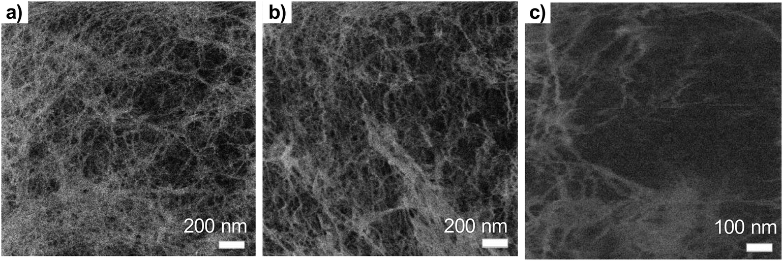
Low magnification HIM images of dried TCNFs with a field of view (FoV) of 400 and 100 μm presents dense and wavy surfaces (Fig. 2a–k). Waviness was most probably caused by sample handling and liquid fluctuations during the drying. In order to see the differences between the actual fibril structures, a closer investigation with higher magnification (FoV 10 μm) was needed. High magnification HIM images (Fig. 1c, f, i and l) show that TCNF-surfaces consisted of a very fine fibrillar material. The CPD-dried samples resembled each other also at higher magnification. Rough estimation of fibril dimensions from the HIM images showed approximately 20 nm-wide fibrils, or fibril bundles, in all samples. Accurate statistical analysis of fibril dimensions and distributions was not possible as the sample degraded during imaging or pictures were too noisy (Fig. 3). TCNFs are found to consist of single fibrils of 3–4 nm in width14 but fibrils of those dimensions could not be distinguished here. There were also much thicker 100 nm wide fibril bundles in the cryofixed samples. Similar structural differences between freeze dried and CPD dried commercial-CNF36 and enzymatic-CNF15 have been observed before with SEM.
 | ||
| Fig. 2 HIM-images of dried TCNFs with different magnifications. (a), (b), (c) cryo-LN2, (d), (e), (f) cryo-LPGS, (g), (h), (i) CPD (EtOH, AE) and (j), (k), (l) CPD (GA, OsO4, EtOH). Top row FoV 400 μm, middle row FoV 100 μm and bottom row FoV 10 μm. Fig. 1i and l show clearly the holes caused by the ion beam. | ||
 | ||
| Fig. 3 The effect of the ion dose to the beam damage on the TCNFs (a) ion dose 4 × 10¹³ ions per cm2 (b) 9 × 10¹³ ions per cm2 (c) 4 × 10¹⁴ ions per cm2 (eqn (2)). | ||
The formation of clear TCNF-films was more severe in cryo-LN2 samples than cryo-LPGS samples. The heterogeneous structure and the film formation indicated that there was ice crystal formation during cryofixing of the sample that pushed the fine material to the edges of the ice crystals.10,16,40,47 The CPD-dried samples showed a more homogenous microstructure. In addition to the small size, TCNFs have high negative charge and high specific surface area,14 meaning that they bind a lot of water in their structure. Removal of the water in such a way that the fine fibril structure remains open is challenging and was not fully achieved with the used cryofix-methods.
Detection of single fibrils turned out to be challenging because of the sample degradation during the imaging. Especially, the CPD-dried TCNFs were sensitive at higher magnifications. Imaging, as in Fig. 2c, f, i and l, was conducted by first using the 2 μm FoV to focus a beam and align the flood gun and then the actual image was taken with 10 μm FoV. Because of the focusing step, a clear hole was formed to the center of the image as can be seen in Fig. 2i and l. Smaller FoV had a higher ion dose per area and to confirm that the effect was dose based, the imaging was done to the fresh areas with different doses by adjusting the amount of averaging. The total ion dose was calculated with eqn (2):
 | (2) |
With dose of 4.9 × 10¹³ ions per cm2 some fibrillar network could be resolved, but the noise level was quite high, which caused the graininess of the image (Fig. 3a). When the dose was doubled (Fig. 3b), some deformations of the fibril structure was detected already. Interestingly, this dose was under the theoretical limit of the sub-nanometer imaging because there were 0.9 ions per nm2. When tenfold dose was used (Fig. 3c) the structure of the fibril network was collapsed leaving some individual fibrils drift over the imaging area.
Degradation of the bio-based materials during the HIM-imaging has not been described in the literature previously. For example, Joens et al. (2013)26 demonstrated how biological organisms can be imaged with high magnifications without damage and in the study by the Leppänen et al. (2017)22 the dose 1.1 × 10¹⁶ ions per cm2 was used to image the dried agar gel network of 10 nm fibrils with no clear damage. Comparison of the ion doses among the literature is challenging because usually not all the imaging parameters are listed. Fox et al. (2013)48 studied a graphene flakes with HIM and Raman spectroscopy and found that dose of 1017 ions per cm2 was required for proper edge contrast to obtain sub-nanometer resolution and 5 × 10¹⁴ ions per cm2 already caused significant damage to graphene lattice. Livengood et al. (2009)49 studied the defect formation in the silicon and copper by HIM and found that with over 5 × 10¹⁵ ions per cm2, subsurface lattice dislocations are found from the TEM cross-sections. These materials are quite different compared to the polymeric CNFs and the direct comparison is not possible.
CNFs consist of cellulose chain bundles with alternating amorphous and crystalline regions having intermolecular hydrogen bonding between the chains on the crystalline part.50,51 The amorphous regions of the network can be considered the weakest points of the structure. Most probably, the ionization of the cellulose by the ion beam, especially in the amorphous regions collapses the structure. Actually, single ion can cause several ionizations because it is known that secondary electron yield of helium ranges from 3 to 10 depending on the material18 Crystalline CNCs, in which the amorphous regions are no longer present, have been imaged with HIM without similar degradation.21,28 However, the quality and magnification of the images and sample preparation methods cannot be directly compared to this work.
Cellulose-based materials have been found to be a highly sensitive also to the electron beams and the imaging of the single cellulose nanofibril or cellulose nanocrystal is challenging with TEM.52 More specifically, a critical dose where the diffraction from the crystalline part of nanocellulose has been halved as the sign of destruction has been found to be about 6 × 10¹⁵ electrons per cm2. This is about 10-times more than the helium ion dose causing the collapse of the fibrillar network in our experiment.
An interesting application of the beam damage is demonstrated in Fig. 4, which shows the time series over the sample area with 0.3 pA ion current with total imaging time of couple of minutes. The overall structure in the first figure was quite plain with no individual fibrils observed. When the same area was imaged multiple times, a hole started to form in the right-upper corner as a loosely bound film-like fibril layer on top of the sample milled away revealing the underlying fibril network. This, so-called “unwrapping” property of the ion beam could be generally utilized to detect different materials based on the milling rate. The image area shifts a little bit upward and right during the imaging, which was also a common finding. The fibril network underneath was most likely collapsing and resulted in an overall change of shape. In principle, helium ions can penetrate tens of μm deep with this acceleration voltage, which means that also the structure underneath the surface can be damaged.
 | ||
| Fig. 4 Time series of the same area of TCNFs dried with CPD (GA, OsO4, EtOH) showing the effect of beam damage (or ion milling) on the sample surface within seconds when using the 0.3 pA ion current. Total imaging time 80 seconds (8 s per image). Imaged using a 16-line average with FoV 1 μm. Scale bar is 100 nm for all the images. | ||
Traditionally OsO4 has been used to reduce sample charging during imaging with SEM.53,54 In the current study the fixation with glutaraldehyde and OsO4 (Fig. 1l) did not protect the TCNFs against degradation. Atomic layer deposition or chemical vapour deposition of titanium oxide16,31 or sputtering of a Pt or Au/Pd layer on the sample surface could provide a protective layer for fibrils and enable imaging with high magnifications; however, metal sputtering can distort the fibril dimensions26,55,56 and possibly damage the finer fibril structure.
3.2. Specific surface area (SSA) of TCNFs
Quantitative evaluation of the differences between the gentle drying methods of TCNFs was done by using BET-analysis, which determines the specific surface area (SSA) of a material that is accessible to nitrogen. In the case of TCNFs, the higher the SSA, the more open the structure and the less coalescence of fibrils has taken place during drying. All of the samples had a type IV N2-sorption isotherm curves with a type H3 hysteresis loop (Fig. 5), which means monolayer-multilayer adsorption of nitrogen on mesoporous structure with pore widths between 2–50 nm.57,58 This hysteresis type typically indicates that the structure was formed of aggregates of platy particles with slit-shaped pores (Fig. 6).11,32,57–60 This slit-shape possibly makes pores prone to collapse during drying, as surfaces want to minimize their energies by binding to each other and the closer they are, the stronger are the surface energies leading to collapse.61 Samples dried with cryo-LN2 did not show any hysteresis loop in the N2-sorption isotherms. When the adsorbed quantities were plotted as relative values (Fig. 5b; the adsorbed quantity divided by the highest detected adsorption), a small hysteresis loop could be detected. There was a steep increase in the isotherms after the relative pressure of 0.82, and because capillary condensation in mesopores occurs at the higher pressure values, the result indicates that most of the pores were larger in size. This was also seen in the pore size distribution (Fig. 7.) of the samples where most of the pores were in the mesopore and micropore range (15–100 nm). Over 50 nm pores or pores under 2 nm cannot be detected accurately by BET, and for this reason, it is probably not the most suitable method for fibrillated materials like TCNFs, but the results were still useful for comparing differences between the samples in the current study. | ||
| Fig. 5 (a) N2-sorption isotherms of TCNFs dried with gentle drying methods (b) relative N2-sorption isotherms of cryo-N2 and CPD (EtOH, Ac) dried TCNFs. | ||
 | ||
| Fig. 6 A sketch of possible configuration of a slit-shaped pore between two cellulose nanofibrils. | ||
 | ||
| Fig. 7 Estimated pore size distribution obtained using BET method of the TCNFs dried with different gentle drying methods. Average pore width (nm) on the x-axis at logarithmic scale and pore volume (cm3 g−1) on the y-axis. | ||
Table 1 shows the mean values of SSA, equivalent pore size, pore volume, and fibril diameter values. The Barrett–Joyner–Halenda (BJH) method was used to calculate the pore size distributions of the samples. The CPD-dried samples adsorbed more nitrogen than cryofixed samples and had higher SSA, equivalent pore size and pore volume. CPD (EtOH, Ac) samples had the largest SSA (386 m2 g−1), equivalent pore size (14.3 μm) and pore volume (1.4 cm3 g−1). The equivalent pore size was similar to the rest of the samples (around 11 μm) but the pore volume was significantly lower for cryofixed samples than for CPD samples. Less than 2% of all pores in all samples were of micro scale, and the rest of the pores were mesopores or larger (Table 1 and Fig. 7). This could mean that even though the volume of the pores in cryofixed samples was lower than in CPD samples, the pore structure was similar. According to the results, CPD drying was able to prevent the coalescence of the fibril structure better than cryofixing; however, most of the micropores in the structure were not preserved or could not be detected. As high SSA values as 500–600 m2 g−1 have been reported for TEMPO-oxidized liquid crystalline CNF-aerogels dried by using CPD and EtOH–solvent exchange.34 The liquid crystalline arrangement achieved by acid-treatment could have promoted the structure stability, which was also observed as high toughness of the dried material. CPD has been reported to be a promising drying method also for TCNF-nanopapers, yielding SSA values of 480 m2 g−1 measured by N2-sorption40 and TCNFs dehydrated with EtOH and AE before CPD showed higher nitrogen adsorption and SSA than samples fixed with GA and OsO4 before dehydration in EtOH. The last AE step could be more beneficial for CPD as the CO2-gas is more miscible with AE than with EtOH.62 In electron microscopy, GA in combination with OsO4 is a commonly used protein fixative of both plant and animal samples.53,63 On the other hand, it has been observed to be more efficient in preservation of internal plant structures than surfaces,63 and did not provide any significant support for cellulose-fibril structures against the ion beam damage in the current study.
| BET surface area | Pore sizeb | Fibril diameter | Pore volumea | Micropore volume <2 nm | |
|---|---|---|---|---|---|
| m2 g−1 | nm | nm | cm3 g−1 | cm3 g−1 | |
| a Single point desorption total pore volume of pores less than 193.5 nm width at p/po = 0.990.b Desorption average pore diameter (4V/A by BET). | |||||
| Cryo-N2 | 41.8 | 10.7 | 59.8 | 0.11 | 0.0012 |
| Cryo-LPGS | 171.8 | 11.6 | 14.6 | 0.50 | 0.0036 |
| CPD (EtOH, Ac) | 385.7 | 14.3 | 6.5 | 1.38 | 0.0193 |
| CPD (GA, OsO4, EtOH) | 375.0 | 11.2 | 6.7 | 1.05 | 0.0176 |
Again, cryo-LPGS samples showed higher nitrogen adsorption and SSA (172 m2 g−1) than cryo-LN2 samples (SSA 42 m2 g−1). LN2 is known to suffer from the Leidenfrost-effect, and the low SSA was probably a result of the coalescence of fibrils by the ice crystal formation. The corresponding results of drying efficiency of cellulose microfibrils (CMF) with CPD, LN2 and LPGS have been previously reported.15 Sehaqui et al. (2011)11 reported a SSA of 150–280 m2 g−1 for TCNFs dried from water using solvent exchange to EtOH and tert-butanol and cryofixing with LN2. Exchanging the water inside the material to a solvent with low surface tension has been shown to increase the SSA also for regenerated cellulose (160–190 m2 g−1).10 Thus, it could be possible to increase the SSA of cryo-LPGS samples by first conducting a solvent-exchange of the samples, like it is done with samples prepared for CPD. On the other hand, if the target is to image TCNFs as they appear in water, where certain charges and interactions between fibrils occur, the solvent-exchange from water to a non-polar solvent could also change these interactions and the surface structure. Thus, it is not obvious that the higher SSA value of the solvent-exchanged samples really describes the sample structure in aqueous conditions.
The calculated equivalent fibril diameters of TCNFs were approximately 7 nm, 15 nm and 60 nm for CPD, cryo-LPGS and cryo-LN2 dried samples, respectively. Large fibril diameters of cryofixed TCNFs can be explained by the fibril agglomeration during drying. Multilayer adsorption of nitrogen can increase the detected surface area, which decreases the calculated fibril diameters, and the actual diameters were most likely larger. The BET results (Table 1) supported the observations from the HIM images of TCNFs (Fig. 2). CPD resulted more homogeneous and finer fibril structure, with less intensive film formation compared to cryofixing. As mentioned before, the smallest fibrils observed from the HIM images were approximately 20 nm in width (Fig. 2c, f, i and l), which was significantly larger than the width estimates from the BET-analysis. This could be due to beam damage during the imaging, making the smallest fibrils disappear or due to the multilayer adsorption of nitrogen in the BET-analysis that affected the SSA calculations. In addition, the HIM-images show only the surfaces of the samples and do not represent the whole structure.
Quantitative differences between different drying methods was not obtained by microscopy, and for that N2-sorption and BET-analysis were needed. Based on these results (Fig. 2 and Table 1), the solvent exchange in EtOH/AE combined with CPD drying is the most preferred method, and also involves less hazardous chemicals and liquid exchange steps than treatment with GA/OsO4/EtOH. Solvent exchange with AE combined with CPD is found to result in a high SSA also with the fibres;64 however, is worth to keep in mind that solvent exchange could modify the interactions between the fibrils that occur in water. TCNFs have added carboxyl groups on the cellulose chain, which increases their hydrogen bonding ability in water. When water is exchanged to the less polar media the hydrogen bonding is hindered and can be responsible for more open fibril structure in the dried material. Cryofixing in LPGS surpasses LN2 in SSA values, but cryofixing in LN2 is more simple and faster than cryofixing in LPGS. In order to select a suitable drying method for TCNFs one needs to consider if a highly preserved structure is necessary, and how much time and effort is practical to use.
4 Conclusions
The suitability of HIM for imaging the porous TCNF-aerogels with high resolution was evaluated and different aerogel preparation methods using gentle drying were compared. High-resolution HIM-imaging of TCNFs was compromised by the dose-related damage as not described before with ion beams. Further research is needed about ion beam induced damage on the organic materials to have reliable imaging methods in the future. Comparison of the different gentle drying methods showed that all methods preserved the wet structure of TCNFs at some degree. CPD was considered to be the best method for drying delicate samples with SSA of 386 m2 g−1. Cryo-LPGS provided moderate result with SSA of 172 m2 g−1, but SSA for cryo-LN2 was only 42 m2 g−1, and should be carefully considered if detailed surface structures of wet cellulose fibril materials are studied. Sample handing procedure in the preparation phase seemed also to affect the large-scale structures of the sample, but clear systematic differences between the samples was seen only in nanoscale.Conflicts of interest
There are no conflicts to declare.Acknowledgements
This research was part of the Academy of Finland funded project ExtBioNet (Tailored fibre–fibre interactions for boosted extensibility of bio-based fibre networks, decision No. 285627). The authors thank Mr Panu Lahtinen (Biomass processing, VTT, Espoo) for providing the fibrillated cellulose materials and Ms Mirja Muhola (Thermochemical conversions, VTT, Espoo) for the BET-analysis of the CNF samples.References
- N. Lavoine, I. Desloges, A. Dufresne and J. Bras, Carbohydr. Polym., 2012, 90, 735–764 CrossRef CAS PubMed.
- T. Saito and A. Isogai, Biomacromolecules, 2004, 5, 1983–1989 CrossRef CAS PubMed.
- S. Ahola, M. Österberg and J. Laine, Cellulose, 2008, 15, 303–314 CrossRef CAS.
- K. Torvinen, F. Pettersson, P. Lahtinen, K. Arstila, K. Vinay, R. Österbacka, M. Toivakka and J. J. Saarinen, Flexible Printed Electron., 2007, 2, 024004 CrossRef.
- F. W. Brodin, Ø. W. Gregersen and K. Syverud, Nord. Pulp Pap. Res. J., 2014, 29, 156–166 CAS.
- H. Orelma, I. Filpponen, L.-S. Johansson, M. Österberg, O. J. Rojas and J. Laine, Biointerphases, 2012, 7, 61 CrossRef CAS PubMed.
- M. Hubbe, O. J. Rojas, M. A. Hubbe, A. Ferrer, P. Tyagi, Y. Yin and C. Salas, Bioresources, 2017, 12, 2143–2233 CAS.
- M. A. Hubbe, P. Tayeb, M. Joyce, P. Tyagi, M. Kehoe, K. Dimic-Misic and L. Pal, Bioresources, 2017, 12, 9556–9661 CAS.
- H. Kangas, P. Lahtinen, A. Sneck, A.-M. Saariaho, O. Laitinen and E. Hellén, Nord. Pulp Pap. Res. J., 2014, 29, 129–143 CAS.
- H. Jin, Y. Nishiyama, M. Wada and S. Kuga, Colloids Surf., A, 2004, 240, 63–67 CrossRef CAS.
- H. Sehaqui, Q. Zhou and L. A. Berglund, Compos. Sci. Technol., 2011, 71, 1593–1599 CrossRef CAS.
- N. T. Cervin, C. Aulin, P. T. Larsson and L. Wågberg, Cellulose, 2012, 19, 401–410 CrossRef CAS.
- M. Henriksson, L. A. Berglund, P. Isaksson, T. Lindström and T. Nishino, Biomacromolecules, 2008, 9, 1579–1585 CrossRef CAS PubMed.
- A. Isogai, T. Saito and H. Fukuzumi, Nanoscale, 2011, 3, 71–85 RSC.
- J. T. Korhonen, P. Hiekkataipale, J. Malm, M. Karppinen, O. Ikkala and R. H. A. Ras, ACS Nano, 2011, 5, 1967–1974 CrossRef CAS PubMed.
- M. Kettunen, R. J. Silvennoinen, N. Houbenov, A. Nykänen, J. Ruokolainen, J. Sainio, V. Pore, M. Kemell, M. Ankerfors, T. Lindström, M. Ritala, R. H. A. Ras and O. Ikkala, Adv. Funct. Mater., 2011, 21, 510–517 CrossRef CAS.
- M. Pääkko, M. Ankerfors, H. Kosonen, A. Nykänen, S. Ahola, M. Österberg, J. Ruokolainen, J. Laine, P. T. Larsson, O. Ikkala and T. Lindström, Biomacromolecules, 2007, 8, 1934–1941 CrossRef PubMed.
- B. W. Ward, J. A. Notte and N. P. Economou, J. Vac. Sci. Technol., B: Microelectron. Nanometer Struct.--Process., Meas., Phenom., 2006, 24, 2871 CrossRef CAS.
- L. Scipioni, L. Stern and J. Notte, Microsc. Today, 2007, 15, 12–15 CrossRef CAS.
- M. T. Postek, A. E. Vladar, J. Kramar, L. A. Stern, J. Notte and S. McVey, AIP Conf. Proc., 2007, 931, 161–167 CrossRef CAS.
- M. T. Postek, A. Vladár, J. Dagata, N. Farkas, B. Ming, R. Wagner, A. Raman, R. J. Moon, R. Sabo, T. H. Wegner and J. Beecher, Meas. Sci. Technol., 2011, 22, 24005 CrossRef.
- M. Leppänen, L.-R. Sundberg, E. Laanto, G. M. de Freitas Almeida, P. Papponen and I. J. Maasilta, Adv. Biosyst., 2017, 1700070, 1–8 Search PubMed.
- D. Emmrich, A. Beyer, A. Nadzeyka, S. Bauerdick, J. C. Meyer, J. Kotakoski and A. Gölzhäuser, Appl. Phys. Lett., 2016, 108, 163103 CrossRef.
- M. E. Schmidt, T. Iwasaki, M. Muruganathan, M. Haque, H. Van Ngoc, S. Ogawa and H. Mizuta, ACS Appl. Mater. Interfaces, 2018, 10, 10362–10368 CrossRef CAS PubMed.
- D. C. Bell, Microsc. Microanal., 2009, 15, 147–153 CrossRef CAS PubMed.
- M. S. Joens, C. Huynh, J. M. Kasuboski, D. Ferranti, Y. J. Sigal, F. Zeitvogel, M. Obst, C. J. Burkhardt, K. P. Curran, S. H. Chalasani, L. A. Stern, B. Goetze and J. A. J. Fitzpatrick, Sci. Rep., 2013, 3, 1–7 Search PubMed.
- Z. Li, J. Liu, K. Jiang and T. Thundat, Nano Energy, 2016, 25, 161–169 CrossRef CAS.
- J. Virtanen, M. Janka and S. Tuukkanen, in EMBEC & NBC 2017, IFMBE Proceedings 65, ed. H. Eskola et al., Springer, Singapore, 2018, pp. 1029–1032 Search PubMed.
- G. Daniel and I. Duchesne, in Proceedings of 7th Int. Conf. Biotechnol. in the Pulp and Paper Industry, Vancouver, Canada, 1998, pp. B81–B84 Search PubMed.
- A. C. Pierre and G. M. Pajonk, Chem. Rev., 2002, 102, 4243–4265 CrossRef CAS PubMed.
- J. T. Korhonen, M. Kettunen, R. H. A. Ras and O. Ikkala, ACS Appl. Mater. Interfaces, 2011, 3, 1813–1816 CrossRef CAS PubMed.
- C. Jiménez-Saelices, B. Seantier, B. Cathala and Y. Grohens, Carbohydr. Polym., 2017, 157, 105–113 CrossRef PubMed.
- M. Pääkkö, J. Vapaavuori, R. Silvennoinen, H. Kosonen, M. Ankerfors, T. Lindström, L. A. Berglund and O. Ikkala, Soft Matter, 2008, 4, 2492–2499 RSC.
- Y. Kobayashi, T. Saito and A. Isogai, Angew. Chem., 2014, 126, 10562–10565 CrossRef.
- R. T. Olsson, M. A. S. Azizi Samir, G. Salazar-Alvarez, L. Belova, V. Ström, L. A. Berglund, O. Ikkala, J. Nogués and U. W. Gedde, Nat. Nanotechnol., 2010, 5, 584–588 CrossRef CAS PubMed.
- Y. Peng, D. J. Gardner and Y. Han, Cellulose, 2012, 19, 91–102 CrossRef CAS.
- Y. Peng, D. J. Gardner, Y. Han, Z. Cai and M. A. Tshabalala, J. Colloid Interface Sci., 2013, 405, 85–95 CrossRef CAS PubMed.
- Y. Peng, D. J. Gardner, Y. Han, A. Kiziltas, Z. Cai and M. A. Tshabalala, Cellulose, 2013, 20, 2379–2392 CrossRef CAS.
- S. Brunauer, P. H. Emmett and E. Teller, J. Am. Chem. Soc., 1938, 60, 309–319 CrossRef CAS.
- H. Sehaqui, Q. Zhou, O. Ikkala and L. A. Berglund, Biomacromolecules, 2011, 12, 3638–3644 CrossRef CAS PubMed.
- S. Josset, L. Hansen, P. Orsolini, M. Griffa, O. Kuzior, B. Weisse, T. Zimmermann and T. Geiger, Cellulose, 2017, 24, 3825–3842 CrossRef CAS.
- A. E. Ketola, A. Strand, A. Sundberg, J. Kouko, A. Oksanen, K. Salminen, S. Fu and E. Retulainen, BioResources, 2018, 13, 5319–5342 CAS.
- E. P. Barrett, L. G. Joyner and P. P. Halenda, J. Am. Chem. Soc., 1951, 73, 373–380 CrossRef CAS.
- A. J. Stamm and L. A. Hansen, J. Phys. Chem., 1937, 41, 1007–1016 CrossRef CAS.
- J. Sugiyama, R. Vuong and H. Chanzy, Macromolecules, 1991, 24, 4168–4175 CrossRef CAS.
- M. Rubin and C. Lampert, Sol. Energy Mater., 1982, LBL-14462 Search PubMed.
- F. Jiang and Y.-L. Hsieh, J. Mater. Chem. A, 2014, 2, 350–359 RSC.
- D. Fox, Y. B. Zhou, A. O'Neill, S. Kumar, J. J. Wang, J. N. Coleman, G. S. Duesberg, J. F. Donegan and H. Z. Zhang, Nanotechnology, 2013, 24, 335702 CrossRef CAS PubMed.
- R. Livengood, S. Tan, Y. Greenzweig, J. Notte and S. McVey, J. Vac. Sci. Technol., B: Microelectron. Nanometer Struct.--Process., Meas., Phenom., 2009, 27, 3244 CrossRef CAS.
- R. M. Brown, J. Polym. Sci., Part A: Polym. Chem., 2004, 42, 487–495 CrossRef CAS.
- M. R. Brown and I. M. Saxena, Plant Physiol. Biochem., 2015, 38, 41–53 Search PubMed.
- Y. Ogawa, H. Chanzy and J.-L. Putaux, Cellulose, 2019, 26(1), 17–34 CrossRef CAS.
- G. R. Bullock, J. Microsc., 1984, 133, 1–15 CrossRef CAS.
- M. J. Talbot and R. G. White, Plant Methods, 2013, 9, 1 CrossRef PubMed.
- H. Fukuzumi, T. Saito, T. Wata, Y. Kumamoto and A. Isogai, Biomacromolecules, 2009, 10, 162–165 CrossRef CAS PubMed.
- T. Okamoto and G. Meshitsuka, Cellulose, 2010, 17, 1171–1182 CrossRef CAS.
- K. S. W. Sing, D. H. Everett, R. A. Haul, L. Moscou, R. Pierotti, J. Rouquerol and T. Siemieniewska, Pure Appl. Chem., 1985, 57, 603–619 CAS.
- K. S. W. Sing and R. T. Williams, Adsorpt. Sci. Technol., 2004, 22, 773–782 CrossRef CAS.
- F. Rouquerol, J. Rouquerol, K. S. W. Sing, G. Maurin and P. Llewellyn, Adsorption by Powders and Porous Solids: Principles, Methodology and Applications, Elsevier Science & Technology, 2nd edn, 2014 Search PubMed.
- S. Liu, Q. Yan, D. Tao, T. Yu and X. Liu, Carbohydr. Polym., 2012, 89, 551–557 CrossRef CAS PubMed.
- L.-S. Johansson, T. Tammelin, J. M. Campbell, H. Setälä and M. Österberg, Soft Matter, 2011, 7, 10917 RSC.
- C. J. Chang, C.-Y. Day, C.-M. Ko and K.-L. Chiu, Fluid Phase Equilib., 1997, 131, 243–258 CrossRef CAS.
- A. K. Pathan, J. Bond and R. E. Gaskin, Micron, 2008, 39, 1049–1061 CrossRef CAS PubMed.
- V. A. Lovikka, P. Khanjani, S. Väisänen, T. Vuorinen and T. C. Maloney, Microporous Mesoporous Mater., 2016, 234, 326–335 CrossRef CAS.
| This journal is © The Royal Society of Chemistry 2019 |