 Open Access Article
Synthesis and enhanced visible light photocatalytic CO2 reduction of BiPO4–BiOBrxI1−x p–n heterojunctions with adjustable energy band
Hao Yong Yina,
Yi Fan Zhengb and
Xu Chun Song *c
*c
aCollege of Materials & Environmental Engineering, Hangzhou Dianzi University, Hangzhou, 310018, P. R. China
bResearch Center of Analysis and Measurement, Zhejiang University of Technology, Hangzhou 310014, P. R. China
cDepartment of Chemistry, Fujian Normal University, Fuzhou 350007, P. R. China. E-mail: songxuchunfj@163.com; Fax: +86-591-83465376; Tel: +86-591-87441126
First published on 9th April 2019
Abstract
A series of novel BiPO4–BiOBrxI1−x p–n heterojunctions were successfully prepared by a facile solvothermal method. The morphology, structure and optical properties of photocatalysts were characterized by scanning electron microscopy (SEM), X-ray diffraction (XRD) and ultraviolet visible diffuse reflectance spectroscopy. The visible light photocatalytic activities of BiPO4–BiOBrxI1−x heterojunctions were investigated by photocatalytically reducing CO2. After 4 hours of irradiation, the 5% BiPO4–BiOBr0.75I0.25 heterojunction showed the highest photocatalytic activity with the yields of CO and CH4 up to 24.9 and 9.4 μmol gcat−1 respectively. The improved photocatalytic activity may be due to the formation of BiPO4–BiOBrxI1−x p–n heterojunctions which can effectively restrict the recombination rate of the photoexcited charge carriers. Moreover, the energy band structure of BiPO4–BiOBrxI1−x heterojunctions could be easily adjusted by changing the mole ratio of I and Br. The possible mechanism of the enhancement of the photocatalytic performance was also proposed based on experimental and theoretical analysis. The present study may provide a rational strategy to design highly efficient heterojunctions with an adjustable energy band for environmental treatment and energy conversion.
1. Introduction
Nowadays, the global energy shortage and alarming level of CO2 in the atmosphere have brought more and more pressure for human beings. The photocatalytic reduction of CO2 using semiconductor-based photocatalysts was considered as a promising approach to eliminate the greenhouse effect, which may also provide valuable fuels such as CO and CH4. However, the widely used photocatalyst TiO21–7 can only respond to ultraviolet light due to its larger energy band gap (3.2 V), which limits its effective utilization of solar light. Recently, bismuth-based photocatalysts, such as BiOX (X = Cl, Br, I),8–12 Bi2O2CO3,13 BiOCOOH,14 Bi2WO6,15–17 Bi2MoO6,18,19 BiPO4,20–24 and BiVO4,25 have been intensively investigated and were considered as very promising semiconductor photocatalysts due to their excellent photocatalytic efficiency in decomposing different kinds of organic pollutants.Recently, BiPO4, as a new n-type photocatalyst has been intensively studied due to its excellent photocatalytic performance, electronic properties, stable chemical structure, high specific surface area and low cost. The monoclinic BiPO4 was reported to have higher photocatalytic activity than that of TiO2 for organic pollutants degradation under UV light irradiation.26 Moreover, the inductive effect of PO43− can benefit the separation of photo-induced electron–holes pairs, which is very important in photocatalytic process.27,28 Despite possessing a higher photocatalytic activity, the further application of BiPO4 was still limited by its wider band gap, which can only respond the ultraviolet light accounting for 4% of total solar irradiation.29 Therefore, many methods have been investigated to improve the visible light response of BiPO4 based photocatalysts. Among these methods, modification of BiPO4 surface with suitable narrow band-gap was considered to be a promising strategy to realize its visible light response.
Bismuth oxyhalides compounds BiOX (X = Cl, Br, I), as a kind of p-type photocatalysis active materials, have recently attracted more attention due to their high photocatalytic activity, suitable band gap, high stability, electronic properties, optical properties and non-toxicity.30 BiOX has the internal structure of (Bi2O2)2+ layers interleaved by double slabs of X ions with weak van der Waals interactions along the c-axis, which can form the internal electric fields between (Bi2O2)2+ layers and X slabs. The formed static electric fields can promote effective separation of photogenerated electron–hole pairs, which is a key factor for the improvement of the photocatalytic activity.31,32 However, the photoelectrochemical properties of pure BiOX are still unsatisfactory for practical applications due to the poor light absorption, utilization and stabilization. Therefore, many strategies have been employed to improve the photoelectrochemical properties of BiOX, such as the morphology controlling, semiconductor combining and noble metals doping. Especially, forming a series of solid solutions has been recently proved to be a promising method improving the photocatalytic activity of BiOX (X = Cl, Br, I). For instance, highly solar light induced photocatalytic activities were obtained on the high quality BiOClxI1−x via a hydrothermal process.33 Moreover, the BiOClxBr1−x34–36 and BiOBrxI1−x37 solid solutions with improved photocatalytic activities have also been successfully synthesized. As is known that constructing p–n heterojunction photocatalysts is another efficient method to improve the photocatalytic activity. The p–n heterojunctions can increase the separation probability of photogenerated electron–hole pairs by an additional internal electric field formed in the photocatalysts, which is beneficial for the photocatalytic reaction. Therefore, the construction of p–n heterojunctions between solid solutions of BiOBrxI1−x and BiPO4 may result in highly improved photocatalytic performance.
In this work, a series of novel and energy band adjustable BiPO4–BiOBrxI1−x (x = 0, 0.25, 0.5, 0.75 and 1) composites with p–n heterojunction structures were synthesized by a simple solvothermal method. The band gap structures of the BiPO4–BiOBrxI1−x p–n heterojunctions can be easily adjusted by changing the ratio of Br and I in the solid solution of BiOBrxI1−x, which may further adjust and optimize the photocatalytic performance of the catalyst. The photocatalytic activity of the BiPO4–BiOBrxI1−x p–n heterojunction, pure BiPO4 and BiOBrxI1−x solid solutions, was evaluated by reduction of CO2 under visible light irradiation (λ > 420 nm). The 5% BiPO4–BiOBr0.75I0.25 heterojunction showed the highest photocatalytic activity in the reduction of CO2. Moreover, a possible visible light induced photocatalytic mechanism on the BiPO4–BiOBrxI1−x p–n heterojunction was also proposed according to the experimental results.
2. Experimental section
2.1 Synthesis of BiPO4 precursor
All the reagents were of analytical grade and used without further purification. The BiPO4 precursor was synthesized via a hydrothermal method. Typically, 5 mmol of Bi(NO3)3·5H2O was firstly dissolved into 20 mL distilled water with strongly stirring. At the same time, 5 mmol of NaH2PO4·2H2O was dissolved into 20.0 mL deionized water. After that, the NaH2PO4·2H2O solution was added dropwise into the Bi(NO3)3·5H2O solution under strongly stirring. After 30 min of stirring, the mixed suspension was transferred into a 50 mL of Teflon-lined stainless steel autoclave and maintained at 140 °C for 12 h. After cooling down to room temperature, the BiPO4 solid products were collected via centrifugal separation, washed by deionized water for several times, and then dried at 60 °C in oven.2.2 Preparation of BiPO4–BiOBrxI1−xheterojunctions
A series of BiPO4–BiOBrxI1−x heterojunctions, BiOBrxI1−x (x = 0, 0.25, 0.5, 0.75 and 1) with different mole ratios of BiPO4 (2%, 5% and 10%), were prepared via a facile solvothermal method. Taking 5% BiPO4–BiOBr0.75I0.25 (x = 0.75) as an example, 5 mmol of Bi(NO3)3·5H2O was firstly dispersed into 20 mL ethylene glycol (EG) to form the solution A. Then 0.08 g BiPO4 was added into the solution A under strongly stirring to form the solution B. Meanwhile, 3.75 mmol KBr and 1.25 mmol KI were dissolved into 20 mL EG to form the solution C. After 30 min of continuous stirring, the solution C was added dropwise into solution B with stirring for another 30 min. The resulting mixture was then transferred into a 50 mL a Teflon-lined stainless steel autoclave, and the temperature was maintained at 140 °C for 12 h. After cooling down to room temperature, the resulting product was separated by centrifugation and washed with deionized water for several times, then dried at 60 °C. Similarly, a series of BiPO4–BiOBrxI1−x (x = 0, 0.25, 0.5, 0.75 and 1) heterojunctions with different mole ratios of BiPO4 (2%, 5% and 10%) were synthesized in the same process by adjusting the ratios of corresponding elements. For comparison, BiOBrxI1−x was also prepared under the same procedure in the absence of BiPO4.2.3 Characterization
Crystal structure of the as-synthesized samples was recorded on a Thermo ARL SCINTAG X'TRA with Cu Kα X-ray source (λ = 0.154![[thin space (1/6-em)]](https://www.rsc.org/images/entities/char_2009.gif) 056 nm) operating at 40 kV and 40 mA. The morphologies of BiOBrxI1−x and BiPO4–BiOBrxI1−x heterojunctions were observed by a Hitachi S-4700 scanning electron microscopy (SEM). The UV-vis diffuse reflectance spectra (DRS) of the as-obtained samples were measured on a Lambda 850 UV-vis spectrophotometer. The X-ray photoelectrons spectroscopy (XPS, ThermoESCALAB250, USA) was employed to examine the electric potentials of the valence band (VB). The electrochemical workstation (CHI-660E, China) with a standard three-electrode chemical cell was used to measure the photocurrent of samples. ITO glass coupled with the as-synthesized samples (0.1 mg) served as the working electrode. The counter electrode and reference electrode were platinum wire and Ag/AgCl electrode, respectively. 0.1 M Na2SO4 aqueous solution was used as electrolyte.
056 nm) operating at 40 kV and 40 mA. The morphologies of BiOBrxI1−x and BiPO4–BiOBrxI1−x heterojunctions were observed by a Hitachi S-4700 scanning electron microscopy (SEM). The UV-vis diffuse reflectance spectra (DRS) of the as-obtained samples were measured on a Lambda 850 UV-vis spectrophotometer. The X-ray photoelectrons spectroscopy (XPS, ThermoESCALAB250, USA) was employed to examine the electric potentials of the valence band (VB). The electrochemical workstation (CHI-660E, China) with a standard three-electrode chemical cell was used to measure the photocurrent of samples. ITO glass coupled with the as-synthesized samples (0.1 mg) served as the working electrode. The counter electrode and reference electrode were platinum wire and Ag/AgCl electrode, respectively. 0.1 M Na2SO4 aqueous solution was used as electrolyte.
2.4 Photocatalytic experiments
The photocatalytic activity of all the samples was estimated by photocatalytic CO2 conversion under visible light irradiation. Typically, 0.05 g of the photocatalyst was firstly dispersed uniformly onto a glass sheet, and then transferred into the reaction cell. Prior to the light irradiation, the air in reaction cell was completely removed by vacuum-treatment. After that 1 atm mixture gas of CO2/H2O serving as reaction gas was introduced into the reaction cell. Then the reaction system was illuminated by a PLS-SXE300 Xe lamp (1900 mW cm−2) with a 420 nm cut off filter. After 4 h visible light irradiation, 1 mL of gas was taken from the reaction cell. Finally, the amounts of CO and CH4 in the reactor were analyzed by a GC (Agilent 7890) with a flame ionization detector (FID, Porapak N 80/100 columns).3. Results and discussion
In order to investigate the morphology and microstructure of the as-obtained products, the BiPO4, BiOBr0.75I0.25 and 5% BiPO4–BiOBr0.75I0.25 composites were characterized by SEM, as shown in Fig. 1. It can be investigated that pure BiPO4 (Fig. 1(a)) exhibited massive microcrystal with smooth surfaces, while BiOBr0.75I0.25 (Fig. 1(b)) was composed of microspheres with average diameter of about 1 μm. Fig. 1(c) displayed the SEM images of 5% BiPO4–BiOBr0.75I0.25 composite. It can be discovered that the BiPO4 microcrystal adhered well to the BiOBr0.75I0.25 microspheres, and no obvious morphology changes can be observed. The chemical element mapping analysis is carried out to further identify the composition of the composites. Fig. 1(d) presented the elemental mapping images of O, P, Br, I and Bi, respectively. It was considered that the brighter area in the elemental map always indicated a higher concentration of the corresponding element. It can be observed that the brighter area of P and Br showed the similar shape of the corresponding morphology of BiPO4 and BiOBr0.75I0.25. Therefore, the elemental mappings may demonstrate the successful formation of the BiPO4–BiOBrxI1−x heterostructures through this facile solvothermal method.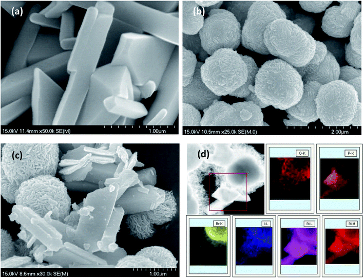 | ||
| Fig. 1 SEM images of (a) BiPO4, (b) BiOBr0.75I0.25, (c) 5% BiPO4–BiOBr0.75I0.25, (d) the element mapping of 5% BiPO4–BiOBr0.75I0.25. | ||
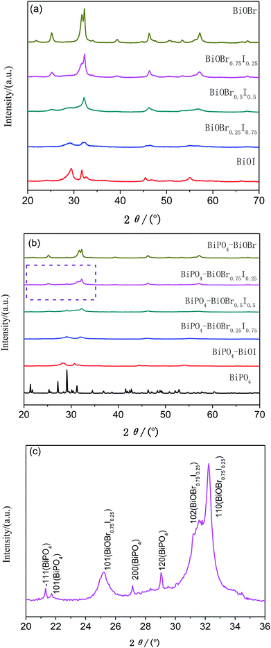
The X-ray diffraction patterns of the as-synthesized BiOBrxI1−x (x = 0, 0.25, 0.5, 0.75 and 1) and BiPO4–BiOBrxI1−x heterostructures were shown in Fig. 2. The distinct diffraction peaks in Fig. 2(a) suggested that all the samples were well crystallized. The diffraction patterns of as-obtained BiOBrxI1−x solid solutions for x = 0 and x = 1 can be indexed to pure BiOI (JCPDS no. 10-0445) and pure BiOBr (JCPDS no. 09-0393) according to the standard card, respectively. It was obviously found that the BiOBrxI1−x diffraction peaks shifted to a higher 2θ position with the increase of x value, which demonstrated the formation of the BiOBrxI1−x solid solutions rather than the simple mixture of BiOI and BiOBr.38 Fig. 2(b) displayed the diffraction patterns of BiPO4 and the as-obtained 5% BiPO4–BiOBrxI1−x heterojunctions. As can be seen that all the BiPO4–BiOBrxI1−x heterojunctions have similar diffraction peaks with the typical BiOBrxI1−x solid solutions. Fig. 2(c) showed the detailed expanded XRD patterns of the 5% BiPO4–BiOBr0.75I0.25 heterojunctions with 2θ ranging from 20 to 36°. It can be distinctly investigated from the XRD of 5% BiPO4–BiOBr0.75I0.25 heterojunctions that three diffraction peaks at 2θ = 25.23°, 31.59° and 32.25° were corresponded well to the (101), (102) and (110) crystal planes of the BiOBr0.75I0.25. While four weak peaks at 2θ = 21.32°, 21.72°, 27.13° and 29.04° can be indexed to the (−111), (101), (200) and (120) crystal planes of BiPO4 (JCPDS no. 15-0767). Moreover, there were no other typical diffraction peaks of BiPO4 being observed on these diffraction patterns, which may be due to the low amount of BiPO4 and its well dispersion in these composites. Besides, no other impurities were detected in the XRD patterns of 5% BiPO4–BiOBrxI1−x heterojunctions.
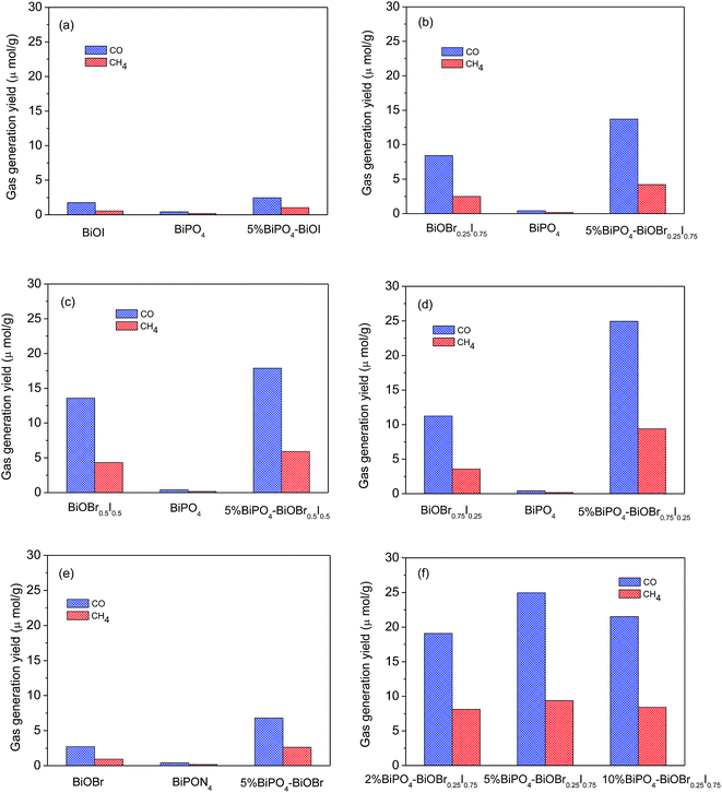
Fig. 3 showed the photocatalytic CO2 conversion activities of BiPO4, BiOBrxI1−x and BiPO4–BiOBrxI1−x heterojunctions under visible light irradiation (λ > 420 nm), which was evaluated by measuring the yield of main products of CH4 and CO. As shown in Fig. 3(a–e), it can be easily found that all the heterojunctions displayed higher photocatalytic activity than the that of pure BiPO4 and BiOBrxI1−x solid solutions (x = 0, 0.25, 0.5, 0.75 and 1). Apparently, the 5% BiPO4–BiOBr0.75I0.25 heterojunction photocatalyst showed the highest photocatalytic activity with the yield of CO and CH4 up to 24.9 μmol g−1 and 9.4 μmol g−1, respectively after 4 h of visible light irradiation. The optimal amount of BiPO4 in BiPO4–BiOBr0.75I0.25 photocatalyst was obtained by comparing the photocatalytic activities of different mole ratios of BiPO4–BiOBr0.75I0.25 (2%, 5% and 10%) photocatalyst. As shown in Fig. 3(f), for the 2% BiPO4–BiOBr0.75I0.25 and 10% BiPO4–BiOBr0.75I0.25 samples, the yield of CO and CH4 were about 19.1, 8.1 and 21.5, 8.4 μmol g−1 after 4 h of visible light irradiation, while the yield of CO and CH4 over 5% BiPO4–BiOBr0.75I0.25 were about 24.9 and 9.4 μmol g−1. Therefore, the 5% BiPO4–BiOBr0.75I0.25 heterojunction have the highest photocatalytic activity, and the optimum value of BiPO4 content percentage should be 5%. Moreover, the results may also indicate that the optimal amount loading of BiPO4 in the BiPO4–BiOBrxI1−x heterojunctions can have more effective contact, which may result in efficient transport of photogenerated electrons and holes.
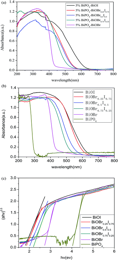
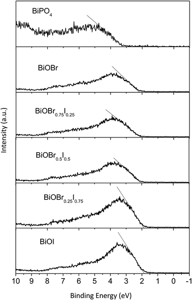
The UV-vis diffuse reflectance spectroscopy (DRS) of the 5% BiPO4–BiOBrxI1−x heterostructures was displayed in Fig. 4(a). It can be found that the absorption edges of the 5% BiPO4–BiOBrxI1−x heterostructures were in the region of 430–650 nm, accompanying with the distinct red shift for the absorption edges with the increase of I. The DRS of the pure BiPO4 and BiOBrxI1−x solid solutions were shown in Fig. 4(b). The absorption edge of pure BiPO4 photocatalyst was observed at about 295 nm, indicating that pure BiPO4 was only in response to the UV light. Meanwhile, the BiOBrxI1−x solid solutions showed a wide response within the visible light range, where the absorption edge extended to about 425–667 nm. It can be clearly seen that the absorption of all the BiOBrxI1−x solid solutions exhibited significantly red shift with the increasing of I, which further proved the formation of the BiOBrxI1−x solid solutions. Based on the DRS results, the band gap energy can be calculated according to the following equation:
 | (1) |
| Eg (eV) | EVB (eV) | ECB (eV) | |
|---|---|---|---|
| BiPO4 | 4.20 | 3.24 | −0.96 |
| BiOI | 1.86 | 1.87 | 0.01 |
| BiOBr0.25I0.75 | 1.96 | 1.90 | −0.06 |
| BiOBr0.5I0.5 | 2.16 | 2.04 | −0.12 |
| BiOBr0.75I0.25 | 2.30 | 2.09 | −0.21 |
| BiOBr | 2.92 | 2.28 | −0.64 |
As the recombination rate of the photogenerated electrons and holes is an important factor influencing the activity of photocatalysts, the photocurrent was carried out to further identify the photocatalytic performance of BiPO4–BiOBrxI1−x heterojunctions. Fig. 6 displayed the photocurrent response of the pure BiPO4, BiOBrxI1−x solid solutions and 5% BiPO4–BiOBrxI1−x (x = 0, 0.25, 0.5, 0.75 and 1) heterojunctions measured with several light on/off cycles under the visible light irradiation. As can be observed, the photocurrent intensity of the 5% BiPO4–BiOBrxI1−x heterojunctions was higher than that of pure BiPO4 and BiOBrxI1−x solid solutions, confirming the obvious improvement of the separation efficiency of photoinduced electron–hole pairs and the effectively reduction of recombination rate. Therefore, the higher segregation efficiency and charge transfer may be the most important factors enhancing the photocatalytic activity of the 5% BiPO4–BiOBrxI1−x heterojunctions for the CO2 conversion under visible light irradiation.
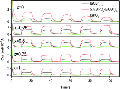 | ||
| Fig. 6 Transient photocurrent response of pure BiPO4, BiOBrxI1−x and BiPO4–BiOBrxI1−x p–n junction (x = 0, 0.25, 0.5, 0.75, 1) under visible light irradiation. | ||
Based on the above results and analysis, the energy band structure diagram of the photocatalysts can be illustrated in Fig. 7. As can be seen that typical nested band structure can be obtained according to the energy band structures of individual BiPO4 and BiOBrxI1−x, which is usually considered detrimental to the segregation of photogenerated carriers. However, the BiPO4 was a typical n-type semiconductor photocatalyst, whose Fermi energy level was near the conduction band (CB). While BiOBrxI1−x was a p-type semiconductor, with Fermi energy level locating closely to the valence band (VB).40,41 Therefore, according to the formation process of a typical p–n junction, when BiPO4 contacted closely with the BiOBrxI1−x, the Fermi levels of p-type BiOBrxI1−x and n-type BiPO4 tend to move up and go down, respectively. Consequently, the whole energy band of BiOBrxI1−x semiconductor will raise up whereas the energy band of BiPO4 will descend to achieve an equilibrium state. Therefore, an inner electric field will be generated at the interface of the p–n junction, which was beneficial to the separation of photoinduced carriers.42 At equilibrium, the region of BiPO4 can be positively charged while the region of BiOBrxI1−x may have negative charges due to the inner electric field between BiPO4 and BiOBrxI1−x. Accordingly, the CB position of BiPO4 became more positive than the CB position of BiOBrxI1−x. When the BiPO4–BiOBrxI1−x p–n heterojunctions was irradiated by visible light, the electron–hole pairs can be excited on BiOBrxI1−x. The photogenerated electrons on the CB bottom of p-BiOBrxI1−x may transfer to the CB of n-BiPO4, while the photogenerated holes still left on the VB of BiOBrxI1−x. Therefore, the photocatalytic performance can be greatly improved by the efficient separation of photoinduced electrons and holes in the established interactive band structures. Moreover, the difference of energy band in BiOBrxI1−x (x = 0, 0.25, 0.5, 0.75 and 1) can not only affect the charge separation efficiency of BiPO4–BiOBrxI1−x (x = 0, 0.25, 0.5, 0.75 and 1) heterojunctions (which can investigated from Fig. 6), but also influence the light absorption property and position of energy band. As can be found from Table 1, the band gap of BiOBrxI1−x became narrower with the increase of I in heterojunctions, which may enhance the visible light absorption and consequently result in the improved visible light photocatalytic activity. Although further increasing of I can lead to much narrower band gap, the CB level of BiOBrxI1−x may shift more positively and VB level more negatively, indicating the lower oxidizability and reducibility on the VB and CB, which may be harmful to the photocatalytic ability. Therefore, rationally adjusting the energy band structures of BiPO4–BiOBrxI1−x heterojunctions can optimize the separation efficiency of photoinduced electron–hole pairs, light absorption property and interaction of energy band, thus resulting in the optimal visible light photocatalytic activity.
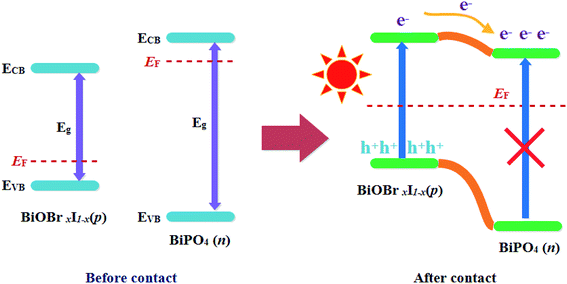 | ||
| Fig. 7 Schematic diagram showing the energy band structure and electron–hole pair separation in the p–n heterojunction under visible light irradiation. | ||
4. Conclusion
In summary, the BiPO4–BiOBrxI1−x p–n heterojunctions have been successfully prepared via a facile solvothermal method. All the heterojunctions showed the superior photocatalytic activity for the CO2 conversion compared with pure BiPO4 and BiOBrxI1−x solid solutions under visible light irradiation. Among them, the 5% BiPO4–BiOBr0.75I0.25 heterojunction displayed the highest photocatalytic efficiency. The enhanced photocatalytic activity was attributed to the effective separation of the photoinduced electron–hole pairs, increased visible light absorption property and interaction of the energy band. The construction of BiPO4–BiOBrxI1−x p–n heterojunction may provide a promising way to design high efficient photocatalysts with tunable band structure for environmental treatment and energy conversion.Conflicts of interest
There are no conflicts to declare.Acknowledgements
This work is financially supported by the National Nature Science Foundation of China (No. 21273034).References
- A. Fujishima and K. Honda, Nature, 1972, 238, 37 CrossRef CAS PubMed.
- M. R. Hoffmann, S. T. Martin, W. Choi and D. W. Bahnemann, Chem. Rev., 1995, 95, 69 CrossRef CAS.
- R. Asahi, T. Morikawa, T. Ohwaki, K. Aoki and T. Taga, Science, 2001, 293, 269 CrossRef CAS PubMed.
- H. G. Yang, C. H. Sun, S. Z. Qiao, J. Zou, G. Liu, S. C. Smith, H. M. Cheng and G. Q. Lu, Nature, 2008, 453, 638 CrossRef CAS PubMed.
- X. L. Wang, H. L. He, Y. Chen, J. Q. Zhao and X. Y. Zhang, Appl. Surf. Sci., 2012, 258, 5863 CrossRef CAS.
- B. X. Lei, L. L. Zeng, P. Zhang, X. F. Zheng, Y. S. Wu, J. Fu and Z. F. Sun, RSC Adv., 2014, 4, 29099 RSC.
- H. Y. Yin, X. L. Wang, L. Wang, Q. L. Nie, Y. Zhang and W. W. Wu, Mater. Res. Bull., 2015, 72, 176 CrossRef CAS.
- S. J. Li, J. L. Chen, Y. P. Liu, K. B. Xu and J. S. Liu, J. Alloys Compd., 2019, 781, 582 CrossRef CAS.
- J. Henle, P. Simon, A. Frenzel, S. Scholz and S. Kaskel, Chem. Mater., 2007, 19, 366 CrossRef CAS.
- X. X. Wang, Q. Ni, D. W. Zeng, G. L. Liao, Y. W. Wen, B. Shan and C. S. Xie, Appl. Surf. Sci., 2016, 396, 590 CrossRef.
- L. F. Lu, L. Kong, Z. Jiang, H. H. C. Lai, T. C. Xiao and P. P. Edwards, Catal. Lett., 2012, 142, 771 CrossRef CAS.
- J. Cao, B. Y. Xu, H. L. Lin, B. D. Luo and S. F. Chen, Chem. Eng. J., 2012, 185–186, 91 CrossRef CAS.
- S. J. Li, S. W. Hu, W. Jiang, Y. Liu, Y. P. Liu, Y. T. Zhou, L. Y. Mo and J. S. Liu, Front. Chem., 2018, 6, 255 CrossRef PubMed.
- S. J. Li, W. Jiang, K. B. Xu, S. W. Hu, Y. Liu, Y. T. Zhou and J. S. Liu, Front. Chem., 2018, 6, 518 CrossRef PubMed.
- S. J. Li, S. W. Hu, W. Jiang, Y. Liu, J. S. Liu and Z. H. Wang, J. Colloid Interface Sci., 2017, 501, 156 CrossRef CAS PubMed.
- L. S. Zhang, H. L. Wang, Z. G. Chen, P. K. Wong and J. S. Liu, Appl. Catal., B, 2011, 106, 1 CAS.
- H. W. Huang, S. B. Wang, N. Tian and Y. H. Zhang, RSC Adv., 2014, 4, 5561 RSC.
- S. J. Li, X. F. Shen, J. S. Liu and L. S. Zhang, Environ. Sci.: Nano, 2017, 4, 1155 RSC.
- S. J. Li, S. W. Hu, W. Jiang, Y. Liu, Y. T. Zhou, J. S. Liu and Z. H. Wang, J. Colloid Interface Sci., 2018, 530, 171 CrossRef CAS PubMed.
- Y. Guo, P. F. Wang, J. Qian, Y. H. Ao, C. Wang and J. Hou, Appl. Catal., B, 2018, 234, 90 CrossRef CAS.
- C. S. Pan and Y. F. Zhu, J. Mater. Chem., 2011, 21, 4235 RSC.
- Y. Guo, P. F. Wang, J. Qian, J. Hou, Y. H. Ao and C. Wang, Catal. Sci. Technol., 2018, 8, 486 RSC.
- H. Xu, Y. G. Xu, H. M. Li, J. X. Xia, J. Xiong, S. Yin, C. J. Huang and H. L. Wan, Dalton Trans., 2012, 41, 3387 RSC.
- C. S. Pan, J. Xu, Y. J. Wang, D. Li and Y. F. Zhu, Adv. Funct. Mater., 2012, 22, 1518 CrossRef CAS.
- K. Sayama, A. Nomura, Z. G. Zou, R. Abe, Y. Abe and H. Arakawa, Chem. Commun., 2003, 2908 RSC.
- C. S. Pan and Y. F. Zhu, Environ. Sci. Technol., 2010, 44, 5570 CrossRef CAS PubMed.
- J. Chen, J. X. Xia, J. Di, M. X. Ji, H. P. Li, H. Xu, Q. Zhang and J. Lu, Colloids Surf., A, 2016, 488, 110 CrossRef CAS.
- H. F. Ye, H. L. Lin, J. Cao, S. F. Chen and Y. Chen, J. Mol. Catal. A: Chem., 2015, 397, 85 CrossRef CAS.
- F. F. Duo, Y. W. Wang, X. M. Mao, X. C. Zhang, Y. F. Wang and C. M. Fan, Appl. Surf. Sci., 2015, 340, 35 CrossRef CAS.
- C. R. Zheng, C. B. Cao and Z. Ali, Phys. Chem. Chem. Phys., 2015, 17, 13347 RSC.
- J. Yuan, J. Wang, Y. She, J. Hu, P. Tao, F. Lv, Z. Lu and Y. Gu, J. Power Sources, 2014, 263, 37 CrossRef CAS.
- Y. Feng, C. B. Liu, H. N. Che, J. B. Chen, K. Huang, C. Y. Huang and W. D. Shi, CrystEngComm, 2016, 18, 1790 RSC.
- W. J. Kim, D. Pradhan and B. K. Min, Appl. Catal., B, 2014, 147, 711 CrossRef CAS.
- Y. L. Qi, Y. F. Zheng and X. C. Song, J. Taiwan Inst. Chem. Eng., 2017, 71, 355 CrossRef CAS.
- J. Yang, Y. J. Liang, K. Li, Y. l. Zhu, S. Q. Liu, R. Xu and W. Zhou, J. Alloys Compd., 2017, 725, 1144 CrossRef CAS.
- H. Gnayem and Y. Sasson, ACS Catal., 2013, 3, 186 CrossRef CAS.
- Z. F. Jia, F. M. Wang, F. Xin and B. Q. Zhang, Ind. Eng. Chem. Res., 2011, 50, 6688 CrossRef CAS.
- Q. Y. Liu, G. Han, Y. F. Zheng and X. C. Song, Sep. Purif. Technol., 2018, 203, 75 CrossRef CAS.
- Q. W. Cao, X. Cui, Y. F. Zheng and X. C. Song, Alloys Intermet. Compd., 2016, 670, 12 CrossRef CAS.
- Q. W. Cao, Y. F. Zheng, H. Y. Yin and X. C. Song, J. Mater. Sci., 2016, 51, 4559 CrossRef CAS.
- W. J. An, W. Q. Cui, Y. H. Liang, J. S. Hu and L. Liu, Appl. Surf. Sci., 2015, 351, 1131 CrossRef CAS.
- F. F. Duo, C. M. Fan, Y. W. Wang, Y. Q. Cao and X. C. Zhang, Mater. Sci. Semicond. Process., 2015, 38, 157 CrossRef CAS.
| This journal is © The Royal Society of Chemistry 2019 |

