 Open Access Article
Design and fabrication of hydrotalcite-like ternary NiMgAl layered double hydroxide nanosheets as battery-type electrodes for high-performance supercapacitors
Chuan Jing†
ab,
Qiang Zhang†ab,
Xiaoying Liu *a,
Yuxiang Chenb,
Xin Wangb,
Luhao Xiab,
Hao Zengb,
Decai Wangb,
Wenzheng Zhangb and
Fan Dong
 c
c
aChongqing Key Laboratory of Catalysis and New Environmental Materials, College of Environment and Resources, Chongqing Technology and Business University, Chongqing 400067, P. R. China. E-mail: lxy_ctbu@163.com; Fax: +86 23 65104131; Tel: +86 23 65104131
bState Key Laboratory of Mechanical Transmissions, College of Materials Science and Engineering, Chongqing University, Chongqing 400044, P. R. China
cResearch Center for Environmental Science & Technology, Institute of Fundamental and Frontier Sciences, University of Electronic Science and Technology of China, Chengdu 611731, P. R. China
First published on 26th March 2019
Abstract
Hydrotalcite is an abundant mineral in nature and can be cost-effectively prepared in the laboratory, but there is almost no discussion about its application in the field of supercapacitors. Herein, hydrotalcite-like ternary NiMgAl LDHs with unique ultrathin nanosheets were designed and fabricated by a facile hydrothermal method. The preparation conditions, such as Ni/Mg molar ratio and hydrothermal reaction time, are evaluated carefully. The physical and chemical properties were also evaluated by various characterization techniques such as XRD, FIB/SEM, EDS, TEM, XPS and BET. The electrochemical behaviors of present samples were determined by CV, CC and cycling tests in a three-electrode system. As a battery-type electrode material in a supercapacitor, owing to the advantage of its unique layered structure, high specific area and obvious redox states, the fabricated Ni2MgAl LDH-24 h nanosheets present an outstanding specific capacitance of 219.2 mA h g−1 at a current density of 1 A g−1 and superior cycling stability with 86.1% capacitance retention over 5000 cycles. Although 45.7% capacitance retention is not satisfactory when the current density increases from 1 to 3 A g−1 due to the NiMgAl LDH's low effective mass and conductivity, it is still a successful case for hydrotalcite application in supercapacitors by doping with Ni2+ to achieve high electrochemical performance. The design and fabrication strategy can facilitate the application of the natural hydrotalcite mineral in the energy storage field.
1. Introduction
The global energy crisis and worsening environmental issues resulting from the massive consumption of fossil fuels have attracted researchers' attention to study alternative clean energy sources. Currently, it is urgent to design and perfect safe, high-efficient, environmentally friendly and renewable clean energy storage devices. Compared with traditional dielectric capacitors, electrochemical capacitors, often called supercapacitors, have drawn a great deal of attention as a primary power source for this rising market due to their outstanding power density, cycling stability and rate performance.1–5 Tremendous efforts have been made to design or develop supercapacitors, including using different nanomaterials and constructing various spatial structures to optimize the electrochemical performance. Transition metal oxides/hydroxides, i.e. NiO, Ni(OH)2, Co3O4, Co(OH)2, MnO2, RuO2 and their composites are commonly considered as promising electrode materials in supercapacitors because of their high capacitance as well as stable electrochemical properties.6–10 However, the expensive cost of transition metal oxides/hydroxides materials hinders their large-scale practical application. Hence, developing novel materials with the merit of low cost and high performance becomes an urgent and challenging issue nowadays.Layered double hydroxides (LDHs) is one kind of 2D layered materials.11 LDHs take various combinations of metallic cationic and anionic species; the structural formula of LDHs is [M1−x2+Mx3+(OH)2][Ax/nn−·mH2O],12 of which M2+ is divalent metallic cation (such as Mg2+, Zn2+, Ni2+, etc.), M3+ is the trivalent metallic cation (such as Al3+, Mn3+, Co3+, etc.) and An− is anion (such as Cl−, OH−, SO42−, CO32−, etc.) arranged in the interlayer. LDHs are commonly employed as adsorbents,13 catalysis,14,15 biological materials16 and drug carrier.17 Recently, LDHs have also attracted much attention for the potential application to battery-type supercapacitor because their layered structure possesses abundant channels to fabricate the intercalation/deintercalation of electrolyte ions and transition metallic elements with multiple redox states. Such structure can simultaneously make use of the merit of electrical double layered capacitance and faradaic capacity.18 At present, a large amount of mature researches are related to LDH electrode materials, such as NiCo LDH,19 NiMn LDH20 and NiAl LDH.21 However, there is almost no discussion of MgAl LDH (hydrotalcite), which is not only one of most natural abundant minerals but also a cost-effective materials prepared in the laboratory. The reason of no discussion could be that the elements of both Mg2+ and Al3+ are members of main group, which does not contribute to the electrochemical performance.
To solve this issue, two strategies can be considered. First, the electroactive element with obvious redox state is necessary for a boost of the pseudocapacitive performance. Second, the specific surface area of the materials should be as large as possible to supply a mass of active site to take part in faradaic redox reactions. As we know, nickel (Ni) is a transition metal element, and has obvious redox state (Ni2+/Ni3+) in electrochemical reaction.22 Hence, a ternary LDH can be constructed by doping nickel into the hydrotalcite to meet the requirement of battery-type electrode materials. In addition, the classic hydrothermal method can be used to prepare the ternary LDH with large specific surface area.
In this work, we synthesized a novel NiMgAl LDH nanosheets via the facile one-pot hydrothermal technique. The preparation conditions of Ni/Mg molar ratio and hydrothermal reaction time were systematically evaluated. The high crystallinity and specific area of Ni2MgAl LDH-24 h brought up an outstanding specific capacitance of 219.2 mA h g−1 at a current density of 1 A g−1 and eminent cycling performance of approximately 86.1% capacitance retention over 5000 cycles at a current density of 5 A g−1. Although 45.7% capacitance retention is not satisfying while the current density increased from 1 to 3 A g−1 due to NiMgAl LDH's low effective mass and conductivity, it is still a successful case for hydrotalcite application in supercapacitor by doping the Ni2+ to achieve the electrochemical performance. The design and fabrication strategy can facilitate the application of natural hydrotalcite mineral in energy storage field.
2. Experimental section
2.1 Materials and chemical reagents
The chemical reagents for the preparation of electrode materials, such as Ni(NO3)2·6H2O, Mg(NO3)2·6H2O, Al(NO3)2·9H2O and urea, were purchased from Alfa Aesar (USA) without any further purification. Deionized water (18.2 MΩ) was used in this experiment. KOH was purchased Chongqing Chuandong Chemical Company (China).2.2 Synthesis of NiMgAl LDHs
NiMgAl LDHs were fabricated by a facile hydrothermal method. Ni(NO3)2·6H2O, Mg(NO3)2·6H2O, Al(NO3)3·9H2O and urea were added into 70 mL deionized water. The feeding molar ratio of metal cations (Ni2+, Mg2+ and Al3+) versus urea is 3.3. The feeding contents of total metal cations were 4 mmol, of which the molar of bivalent metal cations was maintained at 3 mmol, and the molar ratios of Ni2+/Mg2+ are kept at 1, 1.5 or 2. After ultrasonic stirring for 10 min, a clear mixing solution was obtained. Then, the aqueous solution was transferred into a 100 mL Teflon-lined stainless-steel autoclave. The hydrothermal process was conducted at 120 °C for 6, 12 or 24 h. The obtained green colloidal precipitate in the autoclave was washed with deionized water and ethanol for several times and dried at 60 °C for 10 h to obtain the NiMgAl LDH powder. Thus, the obtained samples were labelled according to the molar ratio of Ni2+/Mg2+ and hydrothermal time, such as Ni1MgAl LDH-6 h, Ni1.5MgAl LDH-12 h, Ni2MgAl LDH-24 h. It is worthy of mention that the urea served as a precipitator and anion provider for LDH in the nucleation growth process:23| CO(NH3)2 + 3H2O → 2OH− + 2NH4+ + CO2 | (1) |
| CO2 + H2O → CO3− + 2H+ | (2) |
| Ni2+ + Mg2+ + Al3+ + OH− + CO3− → NiMgAl–CO32− LDH | (3) |
2.3 Materials characterization
The crystallographic structure and phase composition of as-obtained samples were analyzed by the Rigaku D/max-2500 XRD using a Cu Kα radiation source (λ = 1.5406 Å). The morphological investigations of these samples were conducted by focused ion beam (Zeiss Auriga FIB/SEM) equipped with an energy dispersive X-ray spectrometer (EDS) attachment with an acceleration voltage of 5 kV. The lattice information on nanoscale was collected by high-resolution transmission electron microscopy (HRTEM, Zeiss Libra 200) with an acceleration voltage of 200 kV. Specific surface area and porosity of NiMgAl LDHs were determined by N2 adsorption–desorption isotherms at 77 K using micromeritics Gemini VII. The information of chemical states was analyzed by the Thermo ESCALAB 250Xi X-ray photoelectron spectrometer (Al Kα, 1486.6 eV) at the scope range from 0 to 1350 eV.2.4 Electrochemical measurements
The electrochemical behaviors were examined by electrochemical workstation (Chenhua, Shanghai) with the three-electrode system in 6 M KOH solution. The working electrode was assembled as follows: first, active materials, carbon black, and polyvinylidenefluoride (PVDF) were added to N-methyl-2-pyrrolidone (NMP) at a weight ratio of 7![[thin space (1/6-em)]](https://www.rsc.org/images/entities/char_2009.gif) :
:![[thin space (1/6-em)]](https://www.rsc.org/images/entities/char_2009.gif) 2
2![[thin space (1/6-em)]](https://www.rsc.org/images/entities/char_2009.gif) :
:![[thin space (1/6-em)]](https://www.rsc.org/images/entities/char_2009.gif) 1. Second, the mixture is ground continuously to form a uniform slurry. Third, the slurry was coated on nickel foam (1 × 1 cm2) and dried in vacuum at 60 °C for 10 hours to obtain working electrodes. The active mass on the electrode is about 1.5–2 mg. Platinum foil (1 × 1 cm2) was used as the counter electrode and saturated Hg/HgO electrode (SCE) as the reference electrode. The as-fabricated electrodes were characterized by the cyclic voltammetry (CV) and galvanostatic charge–discharge (CC) method in the potential range from 0 to 0.4 V. The electrochemical impedance spectroscopy (EIS) was characterized at the frequency range of 100 kHz to 0.01 Hz with a disturbance voltage of 5 mV at the steady-state open-circuit potential. The specific capacity (Cs) of the samples was determined from CC process by the equation as follows:24
1. Second, the mixture is ground continuously to form a uniform slurry. Third, the slurry was coated on nickel foam (1 × 1 cm2) and dried in vacuum at 60 °C for 10 hours to obtain working electrodes. The active mass on the electrode is about 1.5–2 mg. Platinum foil (1 × 1 cm2) was used as the counter electrode and saturated Hg/HgO electrode (SCE) as the reference electrode. The as-fabricated electrodes were characterized by the cyclic voltammetry (CV) and galvanostatic charge–discharge (CC) method in the potential range from 0 to 0.4 V. The electrochemical impedance spectroscopy (EIS) was characterized at the frequency range of 100 kHz to 0.01 Hz with a disturbance voltage of 5 mV at the steady-state open-circuit potential. The specific capacity (Cs) of the samples was determined from CC process by the equation as follows:24
 | (4) |
3. Results and discussion
3.1 Structure and morphology
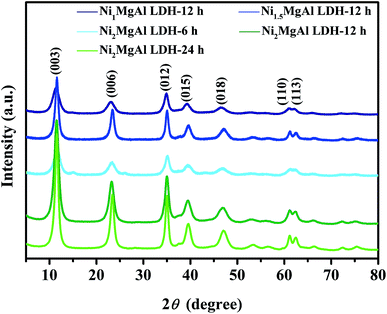
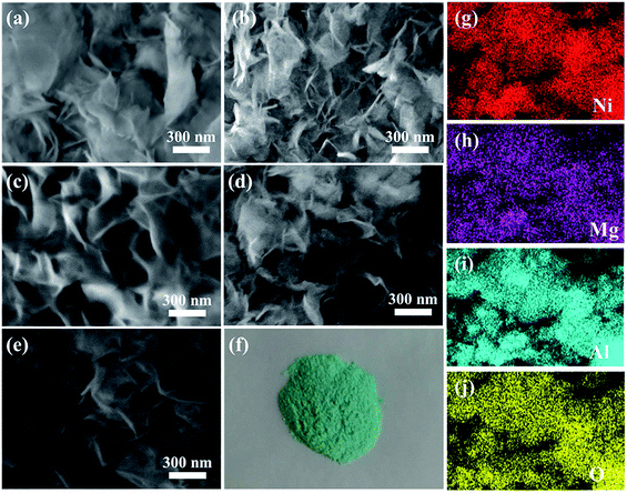
NiMgAl LDHs were prepared by simple one-pot hydrothermal process. Urea served as the sources of alkali and intercalation anion by high temperature self-decomposition at hydrothermal system to facilitate the formation of LDH. The schematic synthesis route of NiMgAl LDH is presented in Scheme 1. XRD patterns of the NiMgAl LDH are demonstrated in the Fig. 1. All the NiMgAl LDHs present the strong reflections of LDH lattice with a series of (003) and (006) diffraction peaks at low angle indicating the formation of classical brucite-like crystal structure. The diffraction peaks at around 60° correspond to (110). No peak of other phase can be found, indicating the high purity of the as-synthesized NiMgAl LDHs. The lattice parameter a = 2d110 is a function of average radii of the metal cations. The value of parameter a increases slightly as the feeding mole of Ni2+ increases, which can be ascribed to the larger radius of Ni2+ than Mg2+. Interestingly, in both the peak density and peak area, the Ni2MgAl LDH is apparently higher than Ni1MgAl LDH and Ni2MgAl LDH. Similarly, Ni2MgAl LDH-24 h is apparently higher than Ni2MgAl LDH-6 h and Ni2MgAl LDH-12 h. The results suggest that the crystallinity increase with the increasing of reaction time and Ni/Mg molar ratio.Fig. 2 presents the representative SEM images and corresponding EDS mapping of the as-synthesized samples at different reaction conditions. The NiMgAl LDHs are homogeneously grown without any aggregation, which can help to improve its electrochemical performance by increasing the number of exposed active atoms. In addition, the NiMgAl LDHs present dulcet nanosheet structure which also make a prominent contribution to electrochemical behavior by increasing the specific area and active site. Besides, abundant porous structure in NiMgAl LDHs nanosheets can be observed, which is favorable for enhancing the electrolyte diffusion and further enhancing supercapacitor performance. As can be seen from the Fig. 2a–e, no other morphologies can be found from the SEM images of these samples, which suggests the Ni2+ was inserted into the hydrotalcite crystal successfully during the hydrothermal reaction. The relevant EDS mapping of the typical Ni2MgAl LDH-24 h (Fig. 2g–j) shows the homogeneous distribution of Ni, Mg, Al, O, clearly, indicating the effectiveness of the preparation method.
The ultrathin nanosheet structure of Ni2MgAl LDH-24 h is further observed by the TEM (Fig. 3). As can be seen from Fig. 3a, the gossamer-like nanostructure exists in all over the Ni2MgAl LDH-24 h nanosheets and the thickness of nanosheets is around 5 nm (Fig. 3b). The interplanar crystal spacings of 1.95 nm and 2.58 nm are on behalf of (018) and (012) plane of Ni2MgAl LDH-24 h (Fig. 3c), respectively, which is in accordance with the XRD results.
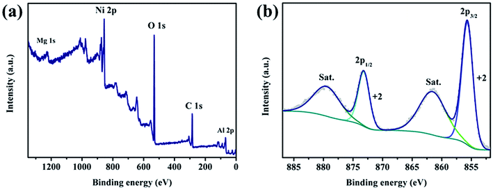
To understand the chemical composition and valence state, the XPS measurement of the typical Ni2MgAl LDH-24 h powder was conducted. As shown in Fig. 4a, the feature peaks of Ni 2p, Mg 1s, Al 2p, O 1s and C 1s are clearly found, suggesting the successful preparation of NiMgAl LDH. The peak of Ni 2p is separated to spin–orbit doublets and satellites (named “Sat.”). Ni 2p3/2 peak is located at 855.7 eV and Ni 2p1/2 peak is located at 873.2 eV. The peaks at 851.6 and 879.7 eV are the “Sat. peaks” of Ni 2p3/2 and 2p1/2, respectively. No additional peak can be fitted in the spectrum indicating that only bivalent nickel ion in the crystal lattice of LDH exists. The results further suggest that the valence state of nickel ion does not change under hydrothermal process. Since magnesium and aluminum do not contribute to the electrochemical performance, they will not be analyzed here.
As we know, the high specific area can increase the contact chance between active material and electrolyte at solid–liquid interface. In addition, the high specific can also decrease the “dead volume” or “dead atoms” in electrode materials, which can facilitate the atomic or volume utilization.25,26 Fig. 5 shows N2 adsorption–desorption isotherms and pore-size distribution (inset) of representative Ni2MgAl LDH with different hydrothermal time (6 h, 12 h and 24 h). All the adsorption isotherms display the type V characteristics with the obvious H3 hysteresis loops corresponding to the microporous and mesoporous structure in two-dimensional nanosheets.27,28 The specific areas of Ni2MgAl LDH-6 h, Ni2MgAl LDH-12 h and Ni2MgAl LDH-24 h are 67.33, 86.72 and 97.70 m2 g−1, respectively. The result suggests that the specific surface area of LDH is increased by prolonging reaction time. The adsorption average pore diameter determined by the Brunauer–Emmett–Teller (BET) method of Ni2MgAl LDH-6 h, Ni2MgAl LDH-12 h and Ni2MgAl LDH-24 h are 12.17, 14.09 and 14.43 nm, respectively. They are all within the mesoporous range, suggesting that it is beneficial to the intercalation/deintercalation of electrolyte ions. Overall, the Ni2MgAl LDH-24 h possesses maximum specific area and mesoporous structure, which has great potential for electrochemical reaction.
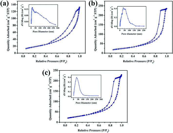 | ||
| Fig. 5 N2 adsorption–desorption isotherms and pore-size distribution (inset) of Ni2MgAl LDH with different hydrothermal time, (a) 6 h, (b) 12 h, (c) 24 h. | ||
3.2. Electrochemical behavior
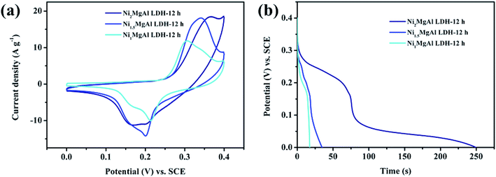
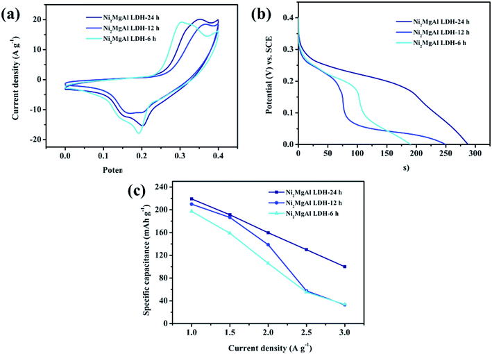
Electrochemical tests of the as-obtained electrode were conducted in three-electrode system. The effects of Ni/Mg molar ratio on NiMgAl LDH at the certain hydrothermal time (12 h) were characterized firstly by the CV and CC curves. As shown in Fig. 6a, the shapes of the CV curves displays the battery-type pseudocapacitive characteristics with a pair of faradic redox peaks corresponding to a reversible reaction:29| Ni(OH)2 + OH− ↔ NiOOH + H2O + e− | (5) |
The cation of Mg2+ and Al3+ does not make contribution to the CV curves because there are no other valence states. This is the fundamental reason why hydrotalcite cannot be used in supercapacitors. Compared with integral area under the CV curves of remaining two samples, the integral area in the Ni2MgAl LDH-12 h curve is the largest one due to the abundant amount of nickel in crystal lattice. It is well known that the specific capacitance is proportional to the integral area of the CV curve,30 which means that the Ni2MgAl LDH-24 h possesses a maximum capacitance. The result can be confirmed by the CC curves of three electrode at current density of 2 A g−1. As shown in Fig. 6b, the nonlinear curves display the battery-type pseudocapacitive characteristics with obvious redox peak. The discharge time of Ni2MgAl LDH-12 h is 249.6 s, longer than that of the Ni1.5MgAl LDH-12 h (34.6 s) and of Ni1MgAl LDH-12 h (17.3 s). The corresponding specific capacitance of Ni2MgAl LDH-12 h is 138.7 mA h g−1, higher than that of the Ni1.5MgAl LDH-12 h (19.2 mA h g−1) and of Ni1MgAl LDH-12 h (9.6 mA h g−1). The discharge time as well as specific capacitance of Ni2MgAl LDH-12 h are nearly 7 times higher than those of Ni1.5MgAl LDH-12 h, and 14 times higher than those of Ni1MgAl LDH-12 h, suggesting that Ni2+ is an important element in these samples to improve their electrochemical performance, and the successful modification of hydrotalcite is an effective strategy to acquire pseudocapacitive characteristics. Hence, the test results show that the sample with the Ni/Mg molar ratio of 2 obtains superior pseudocapacitive performance. Consequently, the Ni/Mg molar ratio of 2 was selected as the criterion of sample preparation in subsequent experiments.
To obtain the best reaction condition, the electrochemical behaviors of Ni2MgAl LDH with different reaction time are studied (Fig. 7). The CV curves of Ni2MgAl LDH with different reaction time are shown in Fig. 7a. The integral area in CV curve for Ni2MgAl LDH-24 h is the largest one among the three as-prepared samples, indicating that the optimal reaction time of 24 h is obtained. The CC curves of above samples at the constant current density of 2 A g−1 are presented in Fig. 7b. The Ni2MgAl LDH-24 h presents the longest discharge time of these samples. According to eqn (4), the specific capacitances of Ni2MgAl LDH-6 h, Ni2MgAl LDH-12 h and Ni2MgAl LDH-24 h are 105.9, 138.7, and 159.8 mA h g−1, respectively, which is consistent with the results of CV curves. The plots of specific capacitance versus different current densities are presented in Fig. 7c. The Ni2MgAl LDH-24 h displays 45.7% retention rate when the current density changes from 1 to 3 A g-1, which is much better than 17.2% and 15.8% retention rates of Ni2MgAl LDH-6 h and Ni2MgAl LDH-12 h, respectively. However, the retention rates of these samples are slightly lower than those of reported nickel-based materials, such as Ni(OH)2@carbon nanosheets,31 Ni(OH)2@carbon nanotubes,32 NiO@carbon,22 NiO.33 The reasons could be as follows: (1) only the element of Ni2+ in NiMgAl LDH can take part in the pseudocapacitive behavior; (2) low conductivity of NiMgAl LDH results in greater diffusion resistance in intercalation or deintercalation process. In general, the Ni2MgAl LDH-24 h delivers excellent capacitances, indicating that the optimal experimental condition is obtained.
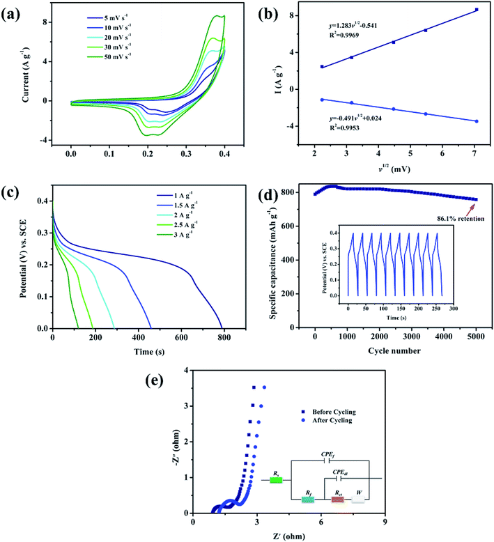
In order to systematically evaluate the pseudocapacitive behavior of Ni2MgAl LDH-24 h, a complete three-electrode test was performed. As shown in Fig. 8a obvious redox peaks appeared during the anodic and cathodic scanning, indicating the oxidation–reduction behavior of Ni+2/Ni+3 according to the formula (5).34 Notably, as the scanning rate increases, the integral area in CV curve increases gradually and the oxidation and reduction peaks move in the direction of the positive and negative potentials, respectively. The phenomenon is the result of diffusion resistance.35 The CV plots are employed to determine the electrochemical reaction kinetics. The current (I) is a function of sweep rates (v), and the corresponding equation can be described as follows:36
| I = avb | (6) |
The CC curves of Ni2MgAl LDH-24 h are further measured to estimate its capacitive behaviors (Fig. 8c). The specific capacitance increases regularly with the decrease of current density. Especially, the specific capacitance of Ni2MgAl LDH-24 h shows an excellent capacity which is up to 219.2 mA h g−1 at a current density of 1 A g−1. Although the retention rate is not satisfying, it is still a successful battery-type electrode material for supercapacitor by using the modification of hydrotalcite. The measurement of CC was further conducted to assess the stability of as-prepared electrode at a current density of 5 A g−1 for 5000 cycles, as shown in Fig. 8d. Over 86.1% of original specific capacitance retention over 5000 cycles suggests outstanding cycling stability. The last ten symmetrical cycle curves illustrate that the structure of the electrode material was not damaged and maintained good coulombic efficiency. Fig. 8e presents the Nyquist plots of the Ni2MgAl LDH-24 h before and after 5000 cycles. Equivalent circuit (R(Q(R(Q(RW))))) is used to fit the electrochemical impedance spectra.37 The semicircle part at a high-frequency range with a linear part at the low-frequency range is found. The semicircle part is assigned to charge transfer resistance (Rct), which is related to the transfer resistance of electron/ions and the linear part is assigned to Warburg impedance (W), which is related to the diffusion rate of the electrolyte ions on the solid–liquid interface. The intersection point between Nyquist plots and x-axis is assigned to solution resistance (Rs), which is related to the intrinsic resistance of the electrolyte.38,39 The slightly lower slope of Ni2MgAl LDH-24 h after cycling indicates that the cycling process has almost no effect on diffusion process of electrolyte ion. The solution resistance (Rs) increases from 0.95 Ω to 1.2 Ω, while the charge transfer resistance (Rct) increases slightly from 1.1 Ω to 2.5 Ω, suggesting excellent cycling stability and durability.
4. Conclusion
Hydrotalcite is one of the natural minerals in nature, but it has no electrochemical properties and cannot be applied in the field of energy. In this paper, we have developed hydrotalcite-like ternary NiMgAl LDHs by a facile one-pot hydrothermal method. The experimental parameters have been carefully optimized by adjusting the Ni/Mg molar ratio and the hydrothermal reaction time. As a battery-type electrode material in supercapacitor, owing to the advantage of unique layered structure, high specific area and obvious redox states, the fabricated Ni2MgAl LDH-24 h nanosheets deliver the outstanding specific capacitance of 219.2 mA h g−1 at a current density of 1 A g−1 and superior cycling stability of 86.1% capacitance retention over 5000 cycles. Although 45.7% capacitance retention is not satisfying while the current density increased from 1 to 3 A g−1, it is still a successful case for hydrotalcite application in supercapacitor by doping the Ni2+ to achieve the high electrochemical performance. We believe that doping the Ni2+ may provide a new design and fabrication strategy to facilitate the application of natural hydrotalcite mineral in energy storage field.Conflicts of interest
There are no conflicts to declare.Acknowledgements
The authors gratefully acknowledge the financial support provided by the Graduate Research and innovation of Chongqing, China (Grant No. CYB18002), the National Natural Science Foundation of China (Grant No. 21576034), the Joint Funds of the National Natural Science Foundation of China-Guangdong (Grant No. U1801254), the State Education Ministry and Fundamental Research Funds for the Central Universities, China (106112017CDJXSYY0001, 2018CDYJSY0055, 106112017CDJQJ138802, 106112017CDJSK04XK11, and 2018CDQYCL0027), and the Innovative Research Team of Chongqing, China (CXTDG201602014). The authors also thank the Electron Microscopy Center of Chongqing University for materials characterizations. We specially appreciate Prof. Qian Chen of Chongqing University greatly for her warm help in improving this article writing.References
- Q. Zhang, H. Chen, L. Luo, B. Zhao, H. Luo, X. Han, J. Wang, C. Wang, Y. Yang and T. Zhu, Energy Environ. Sci., 2018, 11, 669–681 RSC.
- R. Patel, J. T. Park, M. Patel, J. K. Dash, E. B. Gowd, R. Karpoormath, A. Mishra, J. Kwak and J. H. Kim, J. Mater. Chem. A, 2018, 6, 12–29 RSC.
- W. Wei, X. Cui, W. Chen and D. G. Ivey, Chem. Soc. Rev., 2011, 40, 1697–1721 RSC.
- H. Huang, W. Zhang, Y. Fu and W. Xin, Electrochim. Acta, 2015, 152, 480–488 CrossRef CAS.
- Y. Wang, Z. Shi, Y. Huang, Y. Ma, C. Wang, M. Chen and Y. Chen, J. Phys. Chem. C, 2009, 113, 13103–13107 CrossRef CAS.
- H. Chen, B. Zhang, F. Li, M. Kuang, M. Huang, Y. Yang and Y. X. Zhang, Electrochim. Acta, 2016, 187, 488–495 CrossRef CAS.
- K. Tao, P. Li, L. Kang, X. Li, Q. Zhou, L. Dong and W. Liang, J. Power Sources, 2015, 293, 23–32 CrossRef CAS.
- Q. Zhang, Z. Liu, B. Zhao, Y. Cheng, L. Zhang, H.-H. Wu, M.-S. Wang, S. Dai, K. Zhang and D. Ding, Energy Storage Materials, 2018 Search PubMed.
- G. A. Snook, P. Kao and A. S. Best, J. Power Sources, 2011, 196, 1–12 CrossRef CAS.
- J. Li and H. Xie, Mater. Lett., 2012, 78, 106–109 CrossRef CAS.
- M. Shao, F. Ning, Y. Zhao, J. Zhao, M. Wei, D. G. Evans and X. Duan, Chem. Mater., 2012, 24, 1192–1197 CrossRef CAS.
- S. Casenave, H. Martinez, C. Guimon, A. Auroux, V. Hulea, A. Cordoneanu and E. Dumitriu, Thermochim. Acta, 2001, 379, 85–93 CrossRef CAS.
- K. Gupta, J.-B. Huo, J.-C. E. Yang, M.-L. Fu, B. Yuan and Z. Chen, Chem. Eng. J., 2019, 355, 637–649 CrossRef CAS.
- B. Sels, D. De Vos, M. Buntinx, F. Pierard, A. Kirsch-De Mesmaeker and P. Jacobs, Nature, 1999, 400, 855 CrossRef CAS.
- G. Fan, F. Li, D. G. Evans and X. Duan, Chem. Soc. Rev., 2014, 43, 7040–7066 RSC.
- H. B. Yao, Z. H. Tan, H. Y. Fang and S. H. Yu, Angew. Chem., Int. Ed., 2010, 49, 10127–10131 CrossRef CAS PubMed.
- A. Alcantara, P. Aranda, M. Darder and E. Ruiz-Hitzky, J. Mater. Chem., 2010, 20, 9495–9504 RSC.
- X. Cao, H.-Y. Zeng, S. Xu, J. Yuan, J. Han and G.-F. Xiao, Appl. Clay Sci., 2019, 168, 175–183 CrossRef CAS.
- X. Cai, X. Shen, L. Ma, Z. Ji, C. Xu and A. Yuan, Chem. Eng. J., 2015, 268, 251–259 CrossRef CAS.
- Y. Yuan, J. Zhou, M. I. Rafiq, S. Dai, J. Tang and W. Tang, Electrochim. Acta, 2019, 295, 82–91 CrossRef CAS.
- X. Hua, C.-J. Mao, J.-S. Chen, P.-P. Chen and C.-F. Zhang, J. Alloys Compd., 2019, 777, 749–758 CrossRef CAS.
- T. Liu, L. Zhang, B. Cheng, W. You and J. Yu, Chem. Commun., 2018, 54, 3731–3734 RSC.
- X. L. Guo, X. Y. Liu, X. D. Hao, S. J. Zhu, F. Dong, Z. Q. Wen and Y. X. Zhang, Electrochim. Acta, 2016, 194, 179–186 CrossRef CAS.
- Y. Fan, Z. Ma, L. Wang, Y. Dong, T. Jiang, Z. Li, L. Liu and G. Shao, Electrochim. Acta, 2018, 269, 62–69 CrossRef CAS.
- P. Bandyopadhyay, X. Li, N. H. Kim and J. H. Lee, Chem. Eng. J., 2018, 353, 824–838 CrossRef CAS.
- L. Liu, T. Guan, L. Fang, F. Wu, Y. Lu, H. Luo, X. Song, M. Zhou, B. Hu and D. Wei, J. Alloys Compd., 2018, 763, 926–934 CrossRef CAS.
- I. B. Saïd, K. Sadouki, S. Masse, T. Coradin, L. S. Smiri and S. Fessi, Microporous Mesoporous Mater., 2018, 260, 93–101 CrossRef.
- G. Zhang, S. Xiu, Y. Wei, Q. Zhang and K. Cai, CrystEngComm, 2018, 20, 4364–4369 RSC.
- H. Peng, C. Jing, J. Chen, D. Jiang, X. Liu, B. Dong, F. Dong, S. Li and Y. Zhang, CrystEngComm, 2019, 21, 470–477 RSC.
- J.-H. Zhong, A.-L. Wang, G.-R. Li, J.-W. Wang, Y.-N. Ou and Y.-X. Tong, J. Mater. Chem., 2012, 22, 5656–5665 RSC.
- M. Xie, Z. Xu, S. Duan, Z. Tian, Y. Zhang, K. Xiang, M. Lin, X. Guo and W. Ding, Nano Res., 2018, 11, 216–224 CrossRef CAS.
- Q. Qin, J. Liu, W. Mao, C. Xu, B. Lan, Y. Wang, Y. Zhang, J. Yan and Y. Wu, Nanoscale, 2018, 10, 7377–7381 RSC.
- G. S. Gund, C. D. Lokhande and H. S. Park, J. Alloys Compd., 2018, 741, 549–556 CrossRef CAS.
- Z. Tang, C. h. Tang and H. Gong, Adv. Funct. Mater., 2012, 22, 1272–1278 CrossRef CAS.
- S. Li, W. Huang, Y. Yang, J. Ulstrup, L. Ci, J. Zhang, J. Lou and P. Si, J. Mater. Chem. A, 2018, 6, 20480–20490 RSC.
- H. Liang, J. Lin, H. Jia, S. Chen, J. Qi, J. Cao, T. Lin, W. Fei and J. Feng, J. Power Sources, 2018, 378, 248–254 CrossRef CAS.
- C. Jing, Z. Wang, Y. Gong, H. Huang, Y. Ma, H. Xie, H. Li, S. Zhang and F. Gao, Corros. Sci., 2018, 138, 353–371 CrossRef CAS.
- C. Jing, X. Liu, X. Liu, D. Jiang, B. Dong, F. Dong, J. Wang, N. Li, T. Lan and Y. Zhang, CrystEngComm, 2018, 20, 7428–7434 RSC.
- Y. Zhao, X. He, R. Chen, Q. Liu, J. Liu, J. Yu, J. Li, H. Zhang, H. Dong and M. Zhang, Chem. Eng. J., 2018, 352, 29–38 CrossRef CAS.
Footnote |
| † The authors are equally contributing to this manuscript. |
| This journal is © The Royal Society of Chemistry 2019 |


