
 Open Access Article
 This Open Access Article is licensed under a Creative Commons Attribution-Non Commercial 3.0 Unported Licence
Controllable synthesis of aluminum doped peony-like α-Ni(OH)2 with ultrahigh rate capability for asymmetric supercapacitors†
Jinying Wei‡
a,
Daping Qiu‡a,
Min Li*a,
Zhenyu Xiea,
Ang Gaoa,
Hongru Liu*b,
Suhong Yinb,
Dongsheng Yangb and
Ru Yang *a
*a
aState Key Laboratory of Chemical Resource Engineering, Beijing Key Laboratory of Electrochemical Process and Technology for Materials, Beijing University of Chemical Technology, Beijing 100029, China. E-mail: limin9936@163.com; ruyang@mail.buct.edu.cn; Fax: +86 10 64436736
bCentral Research Institute of China Chemical Science and Technology Co., Ltd., Beijing 100029, China. E-mail: 315932577@qq.com
First published on 2nd April 2019
Abstract
Ion substitution and micromorphology control are two efficient strategies to ameliorate the electrochemical performance of supercapacitors electrode materials. Here, Al3+ doped α-Ni(OH)2 with peony-like morphology and porous structure has been successfully synthesized through a facile one-pot hydrothermal process. The Al3+ doped α-Ni(OH)2 electrode shows an ultrahigh specific capacitance of 1750 F g−1 at 1 A g−1, and an outstanding electrochemical stability of 72% after running 2000 cycles. In addition, the Al3+ doped α-Ni(OH)2 electrode demonstrates an excellent rate capability (92% retention at 10 A g−1). Furthermore, by using this unique Al3+ doped α-Ni(OH)2 as the positive electrode and a hierarchical porous carbon (HPC) as the negative electrode, the assembled asymmetric supercapacitor can demonstrate a high energy/power density (49.6 W h kg−1 and 14 kW kg−1). This work proves that synthesizing an Al3+ doped structure is an effective means to improve the electrochemical properties of α-Ni(OH)2. This scheme could be extended to other transition metal hydroxides to enhance their electrochemical performance.
Introduction
Supercapacitors or ultracapacitors are promising for efficient energy storage applications, owing to their superior advantages such as high charge–discharge rates, high power density (up to 10 kW kg−1), and long cycling lifespan (superlong cycle life of over 100![[thin space (1/6-em)]](https://www.rsc.org/images/entities/char_2009.gif) 000 cycles).1–4 Unfortunately, the energy stored per unit mass or volume of supercapacitors is much less than conventional batteries (low energy density), which impedes their extensive applications in the field of energy storage.5 As is known, the energy density (E) of energy storage devices is dependent on both the operating window (V) and specific capacitance (C), that is E = 1/2CV2.6–8 Therefore, strategies for increasing energy density (E) of supercapacitors include improving the specific capacitance (C) and expanding operating window (V).9,10
000 cycles).1–4 Unfortunately, the energy stored per unit mass or volume of supercapacitors is much less than conventional batteries (low energy density), which impedes their extensive applications in the field of energy storage.5 As is known, the energy density (E) of energy storage devices is dependent on both the operating window (V) and specific capacitance (C), that is E = 1/2CV2.6–8 Therefore, strategies for increasing energy density (E) of supercapacitors include improving the specific capacitance (C) and expanding operating window (V).9,10
Taking consideration of their charge storage mechanism, the electrode materials for supercapacitors can be differentiated into two categories: electric double-layer capacitance (EDLC) materials dominated by static charge accumulation at the electrode/electrolyte interface and pseudocapacitance materials dominated by reversible faradaic reactions at or near the interface of electrode/electrolyte.11,12 Generally, pseudocapacitance electrode materials such as transitional metal oxides/hydroxides have high specific capacitances (usually at least one order of magnitude higher than those of traditional carbon-based EDLC), leading to high energy density.13,14 Among numerous transitional metal oxides/hydroxides, nickel hydroxide (Ni(OH)2) is one of the most attractive candidates and has been drawing increasing attention in recent years due to its low-cost, natural abundance, superhigh theoretical specific capacitance (2082 F g−1) and high redox activity.15,16 So far two crystalline forms of nickel hydroxide have been identified: α-Ni(OH)2 and β-Ni(OH)2.12,17 Comparing with another one, the crystal structure of α-Ni(OH)2 is more disorderly, with more randomly oriented layers. Furthermore, α-Ni(OH)2 can directly convert into γ-NiOOH through a faradaic conversion without any nonreversible structural changes. Whereas β-Ni(OH)2 will first convert into β-NiOOH and then this intermediate product is partly converted into γ-NiOOH in strong alkaline electrolyte, which leads to the structural damage of β-Ni(OH)2.18 Moreover, the higher oxidation state of Ni in γ-NiOOH (3.3–3.7) than in β-NiOOH (3.0) gives a higher theoretical specific capacity of α-Ni(OH)2 relative to β-Ni(OH)2.19,20 Therefore, α-Ni(OH)2 is a more desirable pseudocapacitor electrode material. Recent research results show that the interlayer crystal water and foreign anions expand the α-Ni(OH)2 interlamellar spacing to ∼0.78 nm, which crucially provides the passageways for ions to accomplish the full transformation process of α-Ni(OH)2 → γ-NiOOH and achieve higher capacitance.21 However, α-Ni(OH)2 is usually unstable in strong alkaline electrolyte, and will gradually convert into β-Ni(OH)2. It is crucial to take the appropriate strategy to maintain the structural stability of α-Ni(OH)2 during charge–discharge cycle.
Partially substituting other high valence metal ions (for instance, Co2+,22,23 Al3+,24,25 Cu2+,26 Y3+,27 etc.) into α-Ni(OH)2 to form bimetallic complexes can lead to increased structural stability due to the synergetic effect. More concretely, substitution of high valence metal ions will create net positive charges in the α-Ni(OH)2 sheets, and interlayer anions are believed to compensate these extra positive charges.21 For example, Zhang et al. synthesized an Y-doped α-Ni(OH)2 nanosheet which shows an remarkable specific capacitance of 1860 F g−1 at 1 A g−1.27 Liang et al. synthesized a high performance Co-doped Ni hydroxide via a laser-induced process.22 Among all high valence metal ions, Al3+ not only can improve the electronic conductivity and stabilize the crystal structure of metal hydroxide, but also is a non-noble metal.19,24 Ge et al. prepared a Ni–Al LDH/rGO superlattice which exhibits 129 A h kg−1 capacity at 8 min discharge as cathode in alkaline hybrid supercapacitor.25 Hu et al. prepared a Al doped α-MnO2 electrode with a high specific capacitance of 146 F cm−3 under the high mass loading.28 Thus, partially substituting Al3+ into α-Ni(OH)2 to form bimetallic complexes is an efficient strategy to ameliorate the capacitive storage capacity of α-Ni(OH)2-based electrodes. However, there were few reports on electrodes in terms of Al-doped α-Ni(OH)2 for supercapacitors.
In this study, with the aim of constructing supercapacitors electrode material with high structural stability, we have successfully synthesized a peony-like Al3+ doped α-Ni(OH)2 (NIA-x) for the first time via a facile one-pot hydrothermal. When evaluated as electrode materials for supercapacitors, this structure exhibited significantly enhanced specific capacitance, long cycling lifespan and high rate capability, which is attributed to the synergistic effect of Al3+. To improve the potential windows, we assembled asymmetric supercapacitor using NIA-x as the positive electrode and hierarchical porous carbon (HPC) as the negative electrode. This assembled asymmetric supercapacitor shown both high energy and power density. Compared with synthesis schemes in other literatures, the scheme developed in this study is really facile and cost effective which could be extended to other transition metal hydroxide to enhance their electrochemical performance.
Experimental section
Preparation of Al3+ modified α-Ni(OH)2 (NIA-x)
Al3+ doped α-Ni(OH)2 was synthesized via a novel and facile one-pot hydrothermal. First of all, Ni(NO3)2·6H2O (5.0 mmol), Al(NO3)3·9H2O and NH4F (5.0 mmol) were dissolved in 50 mL ultrapure water under stirring to form a green solution, then CO(NH2)2 (40 mmol) was dissolved in the former green solution and continuously stirring for 20 min. Subsequently, the mixed green solution was transferred into an 80 mL Teflon-lined autoclave, then oven heated for 1 h at 160 °C. Upon cooling down to ambient temperature naturally, the resultant precipitate was then separated by filtration with repeated washing with ultrapure water and ethanol and then dried at 80 °C in oven. To investigate the influence of doped Al3+, the different molar ratio 0:1, 0.05:1, 0.1:1, 0.15:1, 0.2:1 and 0.25:1 of Al3+ and Ni2+ in the initial solution were synthesized, and the products denoted as NIA-x (x = Al3+ doping ratio).
Preparation of hierarchical porous carbon (HPC)
HPC was prepared as our previous work.29 The cleaned soybean roots were first carbonized at 500 °C for 2 h under a N2 atmosphere. Then, the obtained char was activated at 800 °C (heating rate, 5 °C min−1) for 2 h under a N2 atmosphere. Finally, HCP was washed with 6 M HCl solution to consume the remaining KOH and then thoroughly washed with deionized water for at least three times.Materials characterization
X-ray diffraction (XRD, Haoyuan DX-2700) was used to investigate the phase compositions of as-obtained products. Scanning electron microscopy (FESEM, Hitachi S-4800) and transmission electron microscopy (TEM, JEM 2100F) were applied to analyze the micromorphology of products and elemental analysis was performed on an energy dispersive X-ray spectroscopy (EDS, S-4800N, Hitachi). Surface characteristics and functional groups were characterized by X-ray photoelectron spectroscopy (XPS, Thermo Fisher) and Fourier transform infrared spectrometer (Thermo Fisher, FT-IR Nicolet-6700). The specific surface area and pore structure were obtained from N2 adsorption–desorption (Micromeritics ASAP 2020), calculated by the Brunauer–Emmett–Teller (BET) model and density functional theory (DFT) method, respectively. Thermogravimetric analysis (TGA) and differential thermal gravity (DTG) were carried out under air with a temperature ramp of 10 °C min−1.Electrochemical characterization of individual working electrode
The electrochemical tests were conducted utilizing a standard three-electrode in 6 M aqueous KOH solution with a Hg/HgO electrode and a platinum foil electrode as the reference and counter electrodes. The working electrode was assembled by adding moderate ethanol to the slurry of electrode materials, polytetrafluoroethylene (PTFE, 15 wt%) and acetylene black (mass ratio of 80:10:10) and ground into a homogeneous slurry. Subsequently, the homogeneous slurry was smeared onto the Ni foam (1 cm × 1 cm) and pressed at 10 MPa for 60 s, then dried at 80 °C for 12 h. The mass loading of NIA-x on the working electrode was approximately 3.0 mg cm−2.
CHI 760E electrochemical workstation was applied to test the cyclic voltammetry (CV) and electrochemical impedance spectroscopy (EIS). LAND CT2001A (Wuhan, China) battery test system was used to measure the galvanostatic charge–discharge (GCD). The mass specific capacitance Csp (F g−1) values of all electrode materials were calculated from the eqn (1).30
| Csp = (I × Δt)/(m × ΔV) | (1) |
Electrochemical characterization of the asymmetric supercapacitors (ASC)
The electrochemical tests of the asymmetric supercapacitors were performed in 6 M aqueous KOH solution, where the NIA-x electrode and HCP electrode were pressed together face to face and with a glass fiber as the separator. The working electrodes were prepared as aforementioned. The charge Q (C) stored by working electrode is calculated following the eqn (2), the mass ratio of NIA-x electrode and HCP electrode is calculated based on the eqn (3). The energy density E (W h kg−1) and power density P (W kg−1) are calculated from the eqn (4) and (5).31,32| Q = Csp × ΔV × m | (2) |
| m+/m− = (C− × ΔV−)/(C+ × ΔV+) | (3) |
| E = CspΔV2/(2 × 3.6) | (4) |
| P = 3600 × E/t | (5) |
Results and discussion
The phase compositions of NIA-x were recorded by X-ray diffraction (XRD) in Fig. 1a. The major diffraction peaks of all samples are corresponding to α-Ni(OH)2·xH2O (JCPDF 38-0715), and the positions of the (003) plane (11.35°) diffraction peaks shifted slightly. Recent researches23,33 have showed that the interlamellar spacing of α-Ni(OH)2·xH2O is one third of the lattice parameter c (Fig. 1b). In our work, as derived from the d-spacing of (003) planes, the interlayer spacing for the NIA-0 is ∼6.4 Å, which is too small to favor the entry of foreign anions. However, this value has significantly increased to ∼7.6 Å after doping with the Al3+, which provides an unobstructed passage (≥7.0 Å) for the entry and storage of foreign anions.34,35 This significant larger spacing between the α-Ni(OH)2 sheets implies that the doped Al3+ creates a positive charge in the Ni(OH)2 layers, and the foreign anions occupy the interlayer space while compensating the charge, resulting in the enlargement of interlayer spacing. It is worth noting that there is not any phase of the doped Al3+ can be detected in the Al-doped samples, suggesting that Al3+ has been successfully doped into the lattice of α-Ni(OH)2 or came into being amorphous Al(OH)3. Moreover, the increasing of Al3+ doping ratio lead to the absence of (101) and (110) planes (33.46° and 59.98°), which is attributed to the randomly oriented and stack of the α-Ni(OH)2 layers.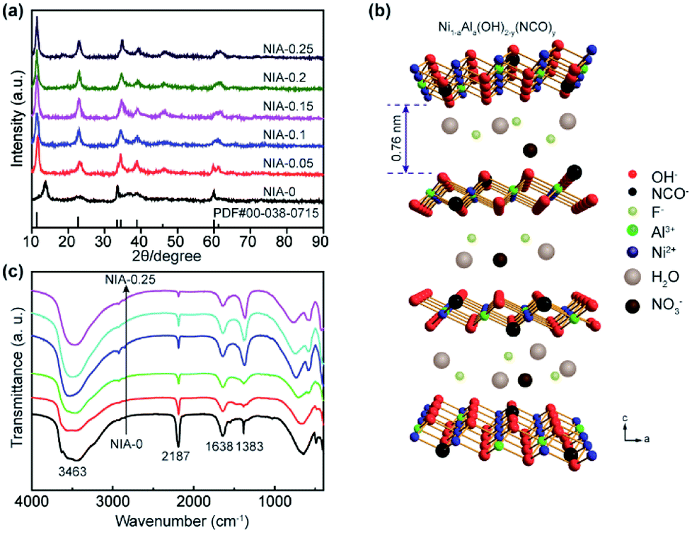 | ||
| Fig. 1 (a) XRD patterns of as-synthesized NIA-x. (b) Schematic illustration of the crystal structure of Al-doped α-Ni(OH)2−y(NCO)y (NIA-x). (c) FTIR spectra of as-synthesized NIA-x. | ||
As shown in Fig. 1c, the surface functional groups of NIA-x were tested by FT-IR. The broad absorption peak at around 3463 cm−1 corresponds to the stretching vibration of O–H bonds, which bears out the presence of intercalated water molecules and hydroxyl groups. The narrow absorption peak at around 1638 cm−1 is attributable to the bending vibration of water molecules and the peak located at 1383 cm−1 is the v3 vibration mode of nitrate anions.22 The spectra below 800 cm−1 correspond to the Ni–O stretching vibration and Ni–O–H bending vibration, respectively.36 The sharp absorption peak around 2187 cm−1 is attributable to C–N stretch of NCO− produced the rapid hydrolysis of urea at high temperature.37,38
Subsequently, X-ray photoelectron spectroscopy (XPS) was applied to characterize the surface characteristics of NIA-0.1. As shown in Fig. S1a,† the survey spectrum of NIA-0.1 shows the existence of Ni, C, O, F, N and Al. The N 1s spectra (Fig. S1b†) shows three major peaks at 397.9 eV, 399.0 eV, 406.1 eV, which correspond to the binding energy of M − N, C![[double bond, length as m-dash]](https://www.rsc.org/images/entities/char_e001.gif) N (isocyanate), and NO (nitrate anion), respectively, demonstrating the presence of NCO− and NO3−. In addition, the peaks with the binding energy 684.5 eV for the F 1s level can be assigned to the F−. It is generally known that H2O molecules, NO3− and F− can be retained within the interlayer region of α-Ni(OH)2 through hydrogen bond.39 With a slight difference, the isocyanate (NCO−) in metal–cyanate complexes can replace lattice OH− and be N-bonded to the Ni2+ and prevent the transformation from α-Ni(OH)2 to β-Ni(OH)2 in strongly alkaline electrolyte.37,40 As seen in Fig. S1c,† the high-resolution Ni 2p3/2 and Ni 2p1/2 peaks are centered at 856.2 and 873.8 eV, respectively, with a spin-energy separation of 17.6 eV assigning to the α-Ni(OH)2,41 which is consistent with the conclusion of the phase compositions analysis. The spectrum of Al 2p (Fig. S1d†) shows a major peak at 75.2 eV, which corresponds to the energy level of Al(OH)3 and demonstrates the presence of Al3+.
N (isocyanate), and NO (nitrate anion), respectively, demonstrating the presence of NCO− and NO3−. In addition, the peaks with the binding energy 684.5 eV for the F 1s level can be assigned to the F−. It is generally known that H2O molecules, NO3− and F− can be retained within the interlayer region of α-Ni(OH)2 through hydrogen bond.39 With a slight difference, the isocyanate (NCO−) in metal–cyanate complexes can replace lattice OH− and be N-bonded to the Ni2+ and prevent the transformation from α-Ni(OH)2 to β-Ni(OH)2 in strongly alkaline electrolyte.37,40 As seen in Fig. S1c,† the high-resolution Ni 2p3/2 and Ni 2p1/2 peaks are centered at 856.2 and 873.8 eV, respectively, with a spin-energy separation of 17.6 eV assigning to the α-Ni(OH)2,41 which is consistent with the conclusion of the phase compositions analysis. The spectrum of Al 2p (Fig. S1d†) shows a major peak at 75.2 eV, which corresponds to the energy level of Al(OH)3 and demonstrates the presence of Al3+.
In addition, thermogravimetric analysis (TGA) and differential thermal gravity (DTG) were used to investigate the thermal behavior of the NIA-0 and NIA-0.1. As shown in Fig. S2,† the weight loss of NIA-0 before 215 °C is 6.56%, which is assigned to the loss of intercalated water molecules and adsorbed water. However, due to the decomposition of aluminium compound, the weight loss of NIA-0.1 at corresponding temperature is much higher than that of NIA-0. In the broad temperature range from 215 to 500 °C, the weight loss of NIA-0 and NIA-0.1 are 22.44% and 20.29%, respectively, which correspond to the decomposition of Ni(OH)2. Notably, the decrease of Ni atom ratio in NIA-0.1 results in a slightly lower weight loss ratio than that in NIA-0. In addition, the results of weight loss calculation show that the actual atom ratio of NIA-0.1 is 0.17.
Based on the above measurement results, we herein propose the structure of Ni1−aAla(OH)2−y(NCO)y·Fa−z(NO3)z·xH2O as shown in Fig. 1b. The layers of Ni1−aAla(OH)2−y(NCO)y is parallel and random orientation, interstratified by interlayer anions and water molecules. Structurally stable Ni1−aAla(OH)2−y(NCO)y, the electrostatic force between Al3+ and the interlayer anions and the hydrogen bonds (H2O, NO3− and F−), greatly improve the stability of the layered structure, which is vital for improving the electrochemical performance of α-Ni(OH)2 at high current. Here, when the Al3+ doping ratio is 0.1, the corresponding structure of NIA-0.1 is Ni0.83Al0.17(OH)2−y(NCO)y·F0.17−z(NO3)z·xH2O. Based on the above, the facile one-pot hydrothermal for NIA-x can be briefly described in Fig. 2. First, the dissolved urea decomposes at high temperature to produce a large amount of OH− (eqn (6)). Then, Ni2+ and Al3+ ions in aqueous solution react with OH− to form bimetallic complexes nanosheets (eqn (8) and (9)). Subsequently, the remaining urea decomposes to produce isocyanate (eqn (7)), and the isocyanate replaces a part of lattice OH− and be N-bonded to the Ni2+. Influenced by the doped Al3+ and the isocyanate anions, the nanosheets self-assemble to be peony-like microspheres.
| CO(NH2)2 + H2O → 2NH3 + CO2 | (6-1) |
| NH3 + H2O → NH4+ + OH− | (6-2) |
CO(NH2)2 ![[left over right harpoons]](https://www.rsc.org/images/entities/char_21cb.gif) NCO− + NH4+ NCO− + NH4+
| (7) |
| Ni2+ + 2OH− → Ni(OH)2 | (8) |
| Al3+ + 2OH− → Al(OH)2+ | (9) |
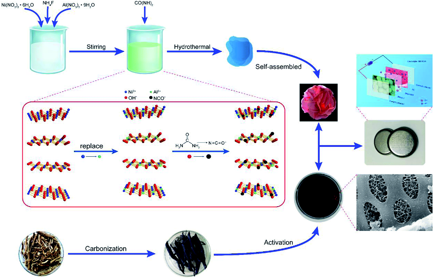 | ||
| Fig. 2 Schematic illustration of the preparation process of Al-doped α-Ni(OH)2−y(NCO)y(NIA-x). | ||
Fig. S3† shows SEM images of NIA-x. The sample self-assemble into irregular microsphere from nanosheets in the absence of Al3+ (Fig. S3b†). But the nanosheets self-assemble into regular peony-like microsphere structures when Al3+ is introduced, and the size reduce obviously (Fig. S3b–f†). It is noteworthy that the number and size of surface pores of peony-like microspheres change obviously with the increase of Al3+ doping ratio. Comparing with the morphology of others, NIA-0.1 (Fig. S3c†) displays a porous structure and more orderly arrangement with thinner nanosheets.
Fig. 3a and b present SEM images of NIA-0.1. Clearly, numerous nanosheets loosely stack together to form peony-like microspheres with 3D network, and the well-defined peony-like microspheres with diameter of about 3–4 μm are monodispersed. In general, this loose 3D porous structure is beneficial to the permeation of electrolyte. The TEM images of NIA-0.1 shown in Fig. 3d and e further demonstrate that interconnected nanosheets are the basic components of peony-like microspheres, which endows the materials with a great deal of pores and channels. Such a unique structure with a plentiful channels and pores can facilitate the electrolyte permeation into the interior, more concretely, reduce the charge transfer resistance and enhance the charge transport speed of electrode/electrolyte interface. The HRTEM image (Fig. 3f) reveals more detailed crystallographic texture information about the NIA-0.1 nanosheets. The interplanar spacing of 0.23 nm in crystal grains corresponds to the (010) plane of α-Ni(OH)2·xH2O (JCPDF 38-0715), indicating that the crystals are arranged along (010) planes. As shown in Fig. 3c, the EDS elemental maps indicate clearly that Ni, O and Al are well-distributed in the entire peony-like microspheres, indicating that Ni and Al mutually dope and grow into nanosheets.
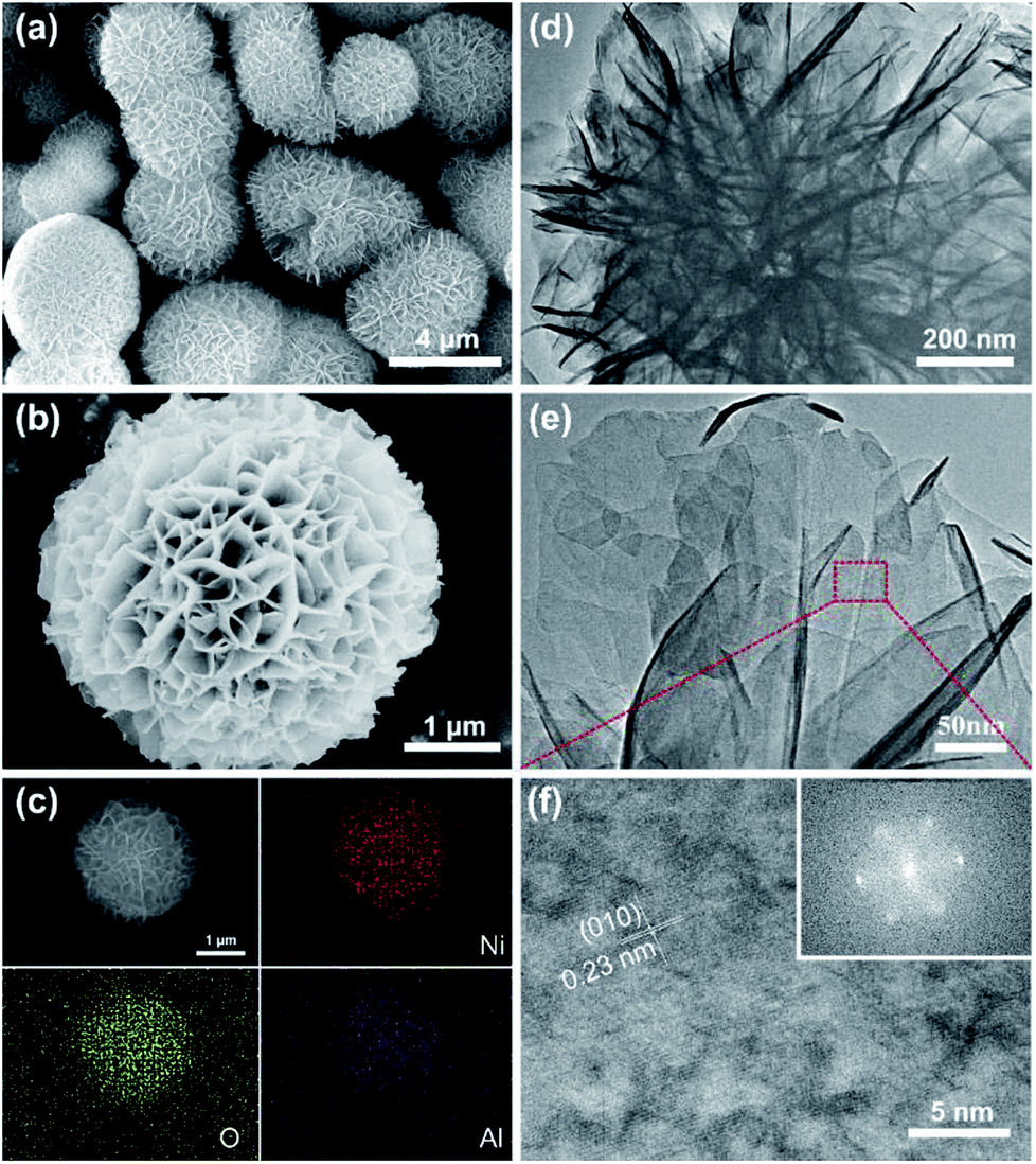 | ||
| Fig. 3 (a) and (b) SEM images of NIA-0.1. (c) EDS mapping of a single flowerlike microsphere. (d) and (e) TEM images of NIA-0.1. (f) HRTEM image of NIA-0.1, inset is the SAED pattern of it. | ||
N2 adsorption–desorption tests were conducted to characterize the specific surface area and pore characteristics of these samples. As shown in Fig. 4a, the N2 adsorption–desorption isotherms of NIA-x are typical type IV isotherms with a clear H3 hysteresis loop, indicating the presence of abundant mesopores. In detail, the appearance of significant hysteresis characteristics at middle relative pressure (P/P0 = 0.45–0.9) indicates that abundant mesopores exist in these samples, and the phenomenon of a drastic increase at high relative pressure (P/P0 = 0.9–1.0) confirms the existence of macropores. The BET specific surface area of NIA-0.1 is 70.5 m2 g−1, higher than NIA-0 (17.4 m2 g−1) and other samples. The distribution curves of all samples are shown in Fig. 4b, All the samples exhibit a continuous pore size distribution from 1 to 110 nm, and possess a similar pore diameter distribution, which is in good agreement with the pore types analysed from the N2 adsorption–desorption isotherms. As is known to all, mesopores can significantly short the transmission distance of electrolyte ions and macropores can act as a buffer for storing the ions in supercapacitors electrode materials.42–44 The porous characteristics and high specific surface area of the pseudocapacitance electrode materials allow more electroactive materials availability for the interfacial reversible faradaic electrochemical reactions, thus more charges will be stored, and resulting in high energy density.
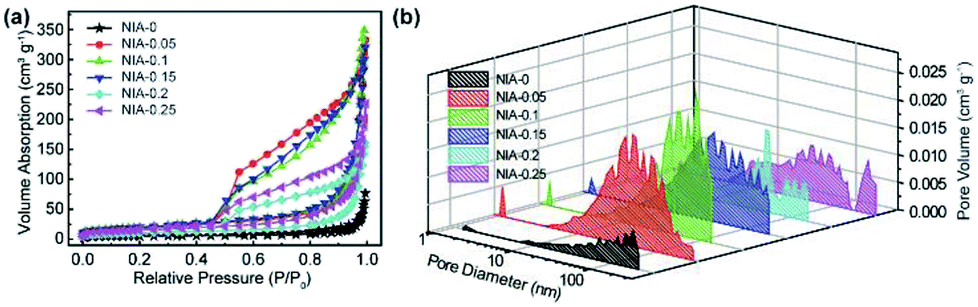 | ||
| Fig. 4 (a) N2 adsorption–desorption isotherms of as-synthesized NIA-x. (b) DFT pore size distributions of as-synthesized NIA-x. | ||
The electrochemical properties of NIA-x were characterized in a three-electrode using 6 M aqueous KOH. Fig. 5a shows the CV curves of NIA-x tested at 2 mV s−1 with an operating window of 0.0 to 0.6 V (vs. Hg/HgO). A pair of strong anodic and cathodic peaks, located at ∼0.45 V and ∼0.35 V (vs. Hg/HgO), is observed in all of the curves, demonstrating that the pseudocapacitive characteristic is the result of reversible faradaic reaction of α-Ni(OH)2 ↔ γ-NiOOH. The faradaic redox process of α-Ni(OH)2 can be expressed as follow:45,46
| α-Ni(OH)2 + OH− ↔ γ-NiOOH + H2O + e− | (10) |
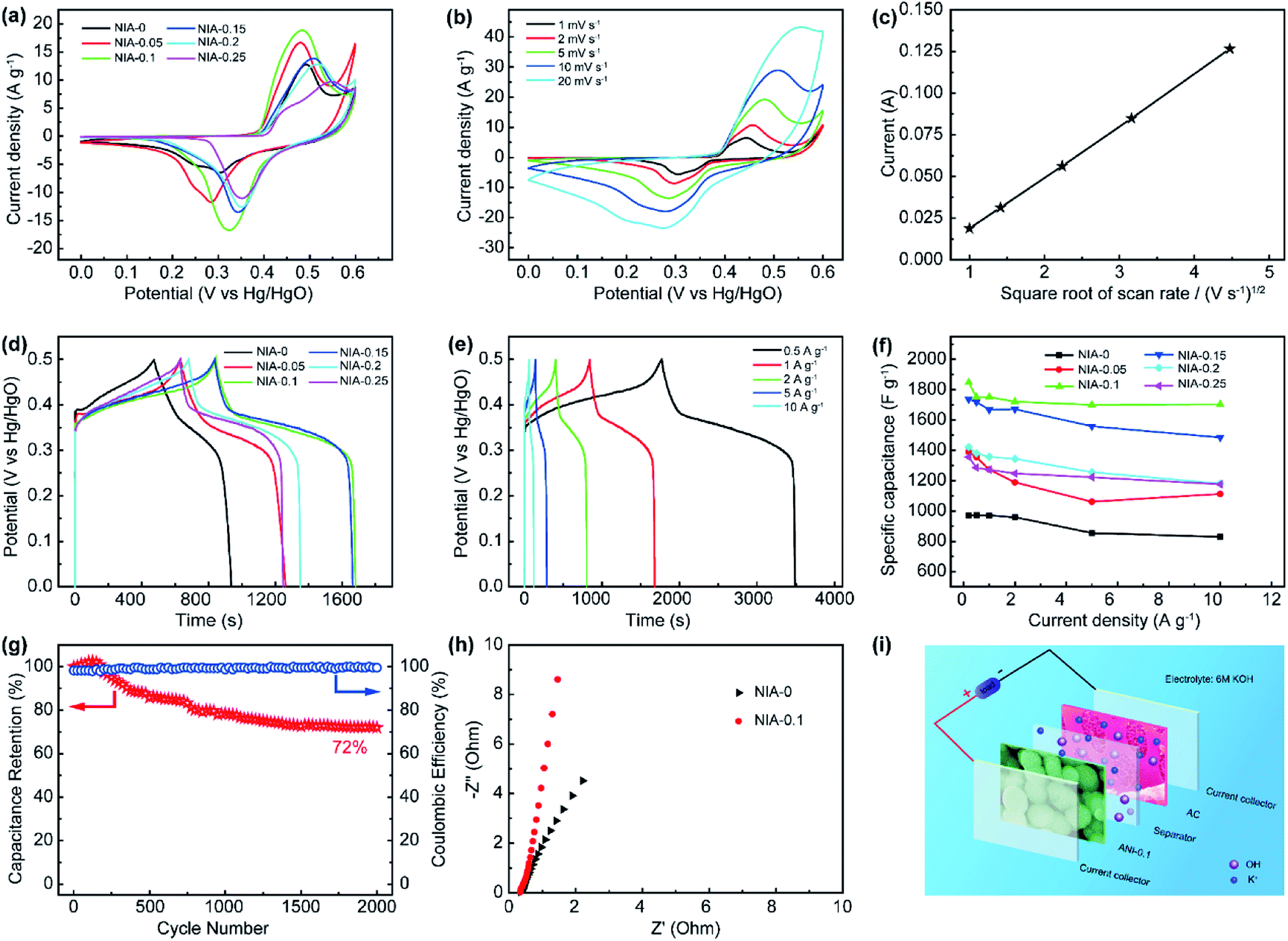 | ||
| Fig. 5 (a) CV curves of as-synthesized NIA-x at a scan rate of 2 mV s−1. (b) CV curves of as-synthesized NIA-0.1 at scan rates from 1 to 20 mV s−1. (c) Relationship between the anodic peak current (Ip) and square root the scan rate (ν1/2). (d) GCD curves of as-synthesized NIA-x samples at a current density of 1 A g−1. (e) GCD curves of as-synthesized NIA-0.1 at various current densities. (f) Specific capacitance values of as-synthesized NIA-x at different current densities. (g) Specific capacitance cyclic stability of NIA-0.1 at a constant current density of 1 A g−1. (h) Comparison of Nyquist plots of NIA-0 and NIA-0.1 electrodes at a potential of 5 mV. (i) Schematic of the structure of the asymmetric supercapacitor device. | ||
The minimum value integral area of CV curve in the absence of Al3+ confirms the positive effect of appropriate Al3+ doping on the electrochemical properties of α-Ni(OH)2. Moreover, the integral area of NIA-0.1 is larger than others, indicating a higher specific capacitance. Fig. 5b presents the CV curves of NIA-0.1 tested from 1 to 20 mV s−1. Clearly, no matter which scan rate there is a pair of significant redox peaks in CV curve, the difference is that the location of oxidation and reduction peaks move toward the positive and negative regions with the increase of scan rate. The dependence between the anodic peak current (Ip) and the square root of the scan rate (ν1/2) is shown in Fig. 5c. The good linear relationship between Ip and ν1/2 confirms that the electrode reaction of NIA-0.1 is a diffusion-controlled process.19,47
To further qualify the specific capacitance of NIA-x, a GCD test was carried out. Fig. 5d presents the GCD curves (0.0 to 0.5 V vs. Hg/HgO) of NIA-x at 1 A g−1. Clearly, all the samples have a clear charge and discharge plateaus at ∼0.35 V and ∼0.3 V (vs. Hg/HgO), respectively. Fig. 5e and S4† show the GCD curves of NIA-x at various current densities, and the corresponding Csp values of all NIA-x at various current densities are shown in Fig. 5f. NIA-0.1 exhibits the highest specific capacitance value, the Csp of NIA-0.1 is 1847, 1752, 1750, 1721, 1703 and 1699 F g−1 at 0.2, 0.5, 1, 2, 5 and 10 A g−1, respectively, whereas for NIA-0 is 970.9, 972.4, 970.1, 959.2, 854.2 and 828.7 F g−1, respectively. Similarly, the Csp of other samples is much higher than NIA-0. Moreover, NIA-0.1 demonstrates the best rate capability (92%) compared with that of NIA-0 (85%), NIA-0.05 (80%), NIA-0.15 (85%), NIA-0.2 (83%), and NIA-0.25 (86%). Obviously, the optimized Al3+ doping ratio is 0.1, and further enhancing the doping ratio on this basis will result in a reduced specific capacitance, inferring that a higher Al3+ content will lead to the formation of other impurities. In that case, the impurities will tightly grow on the surface of α-Ni(OH)2 and hampering ions transport between active substances and electrolytes. Fig. 5g shows the cyclic stability of NIA-0.1 at 1 A g−1. The retention capacitance is 72% after 2000 continuous cycles, exhibiting a good electrochemical stability as a pseudocapacitor electrode. Notably, the slight increase of specific capacitance in first 300 cycles is due to the electrolyte ions were not sufficiently permeated inside the electrode material at the beginning of the test. In addition, the capacity degradation mainly comes from the irreversible transformation of α-Ni(OH)2 to β-Ni(OH)2 when soaked in 6 M KOH electrolyte. From the Nyquist plots shown in Fig. 5h, the equivalent series resistance (Rs, the real axis intercept)48 of NIA-0.1 is 0.33 Ω, smaller than NIA-0 sample, implying the important role of Al3+ in promoting conductivity.
In general, the ultrahigh specific capacitance, good electrochemical stability and superb rate capability of NIA-0.1 is attributed to three aspects: (1) the low crystallinity and high crystal defects are positive to the electrochemical performance; (2) the Al3+ doped α-Ni(OH)2 structure significantly enhances the structural stability of α-Ni(OH)2 during the faradaic redox process; (3) the porous characteristics and high specific surface area improve the number of electroactive sites and reduce the transmission resistance of ions within the electrode material.
To estimate the feasibility of the as-obtained Al3+ doped α-Ni(OH)2 peony-like microspheres for practical application, simple asymmetric supercapacitors (ASC) were further assembled by utilizing the as-synthesized NIA-0.1 and a previously reported hierarchical porous carbon (HPC) as the positive and negative electrodes, respectively,29 which is denoted as NIA-0.1//HPC (Fig. 5i). The HPC electrode exhibits excellent EDLC property at −1.0 to 0.0 V (Fig. S5†) and the specific capacitance of HPC-electrode can reach to a high value (283 F g −1 at 1 A g −1). Clearly, it is suitable to be used as the negative electrode material of ASC. Based on the NIA-0.1 electrode and HPC electrode, the NIA-0.1//HPC was assembled in 6 M aqueous KOH. To obtain a high performance supercapacitor, it is necessary to balance the charges stored at the positive (Q+) and negative (Q−) electrodes.49–51 According to the eqn (2), the charge (Q) stored by single electrode is related to the specific capacitance (Csp), operating window (ΔV) and the mass of electrode materials (m). Considering this charge balance principle (Q+ = Q−), the mass ratio of two electrodes could be calculated from eqn (3). In this work, the optimum mass ratio between the NIA-0.1 and HPC is expected to be m+/m− = 0.32. Fig. 6a shows the CV curves measured at various operating windows for the NIA-0.1//HPC ASC at 10 mV s−1. When the operating window reaches to 1.0 V, the existence of a pair of strong anodic and cathodic peaks (located between 0.8 and 1.0 V) demonstrates that a pseudocapacitive reaction occurs on the surface of the positive electrode (NIA-0.1). As the operating window increases to 1.6 V, more pseudocapacitive reactions (the larger current response) occur. When the operating window expands to 1.8 V, there is obvious polarization appear, indicating the occurrence of oxygen evolution reaction. All of these facts confirm that 1.6 V is the optimal operating window, which is in agreement with the conclusion in Fig. S5d.† The CV curves of the NIA-0.1//HPC ASC from 1 to 50 mV s−1 is shown in Fig. 6b. The combination of both pseudocapacitive and EDLC types of supercapacitor is clearly exhibited at every scan rates, and a pair of redox peaks located between 1.2 and 1.4 V corresponds to the mutual conversion of α-Ni(OH)2 and γ-NiOOH as shown in eqn (10). Fig. 6c shows the GCD curves of NIA-0.1//HPC ASC at various current densities with 1.6 V operating window. The obvious two plateaus (1–1.6 V and 0.05–0.25 V) in GCD curves at different current densities reveal the accumulation of both electrochemical adsorption and faradaic reaction at electrode/electrolyte interface. The Csp of NIA-0.1//HPC ASC calculated according to the total mass of the two electrodes are found to be 140.1, 94, 82, 66.5 and 46.5 F g−1 at 0.2, 0.5, 1, 2 and 5 A g−1, respectively, seen in Fig. 6d. The Ragone plot is shown in Fig. 6e, the energy density of the NIA-0.1//HPC ASC reaches to 49.6 W h kg−1 at a power density of 573.8 W kg−1 and could retain 15.1 W h kg−1 with an ultrahigh 14 kW kg−1. Furthermore, the NIA-0.1//HPC ASC shows higher energy density and power density in the similar electrolyte compared to previously reported Ni(OH)2-based ASC shown in Fig. 6e.52–59 To facilitate application of the NIA-0.1//HPC ASC, we connected two NIA-0.1//HPC ASC in series to light a smiling face consisting of 25 red light emitting diodes (operating voltage 3 V, 20 mA) for at least 10 min as shown in Fig. 6f. All these attractive results confirm that the NIA-0.1//HPC ASC is a promising candidate for capacitive energy storage.
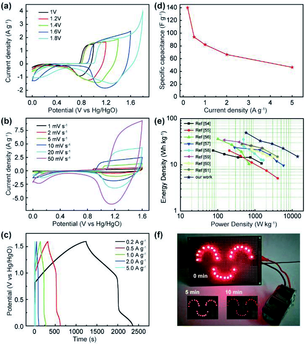 | ||
| Fig. 6 (a) CV curves of NIA-0.1//AC ASC at different potential windows at the scan rate of 10 mV s−1. (b) CV curves of NIA-0.1//AC ASC at scan rates from 1 to 50 mV s−1. (c) GCD curves of NIA-0.1//AC ASC at different current densities. (d) Specific capacitance values of the NIA-0.1//AC ASC at different current densities. (e) Ragone plots of NIA-0.1//AC ASC and compared with some other doping-based or Ni(OH)2-based asymmetric supercapacitors in literatures. (f) Device based on two asymmetric supercapacitors keeps the smiling face lighted for over 10 min. | ||
Conclusions
In summary, an Al3+ doped α-Ni(OH)2 material with peony-like morphology and porous structure has been successfully synthesized through a facile one-pot hydrothermal, which shows an excellent capacitive storage capacity. The Al3+ doped peony-like α-Ni(OH)2 shows an ultrahigh specific capacitance 1750 F g−1 at 1 A g−1, which is almost twice that of pure α-Ni(OH)2. In addition, it exhibits outstanding electrochemical stability (72% retention after running 2000 cycles) and excellent rate capability (1699 F g−1 at 10 A g−1). The outstanding capacitive storage capacity can be attributed to the synergetic effects including low crystallinity, high surface defects, high specific surface area and porous structure. As proof-of-concept application in devices with high energy densities, a simple ASC with NIA-0.1 as the positive electrode and HPC as the negative electrode was fabricated. The as-assembled NIA-0.1//HPC ASC can operate steadily in a 1.6 V operating window and exhibits a high specific capacitance of 140.1 F g−1 with a high energy density of 49.6 W h kg−1. This work suggests that synthesizing Al3+ doped structure is an efficient strategy to improve the capacitive storage capacity of α-Ni(OH)2, and the scheme could be extended to other transition metal hydroxide to enhance their electrochemical performance.Conflicts of interest
There are no conflicts to declare.Acknowledgements
This work was supported by the National Natural Science Foundation of China (51772017).Notes and references
- Y. Wang, Y. Song and Y. Xia, Chem. Soc. Rev., 2016, 45, 5925–5950 RSC.
- L. Q. Mai, A. Minhas-khan, X. Tian, K. Mulonda Hercule, Y. L. Zhao, X. Lin and X. Xu, Nat. Commun., 2013, 4, 2923 CrossRef PubMed.
- P. Simon and Y. Gogotsi, Nat. Mater., 2008, 7, 845–854 CrossRef CAS PubMed.
- S. Chu and A. Majumdar, Nature, 2012, 488, 294–303 CrossRef CAS PubMed.
- J. Niu, R. Shao, J. Liang, M. Dou, Z. Li, Y. Huang and F. Wang, Nano Energy, 2017, 36, 322–330 CrossRef CAS.
- M. Liu, J. Niu, Z. Zhang, M. Dou and F. Wang, Nano Energy, 2018, 51, 366–372 CrossRef CAS.
- N. Choudhary, C. Li, J. Moore, N. Nagaiah, L. Zhai, Y. Jung and J. Thomas, Adv. Mater., 2017, 29, 1605336 CrossRef PubMed.
- J. S. Chen, G. Cao, G. Yang and D. J. Blackwood, ACS Appl. Mater. Interfaces, 2017, 9, 496–504 CrossRef CAS PubMed.
- R. R. Salunkhe, J. Lin, V. Malgras, S. X. Dou, J. H. Kim and Y. Yamauchi, Nano Energy, 2015, 11, 211–218 CrossRef CAS.
- J. Shen, X. Li, L. Wan, K. Liang, B. K. Tay, L. Kong and X. Yan, ACS Appl. Mater. Interfaces, 2017, 9, 668–676 CrossRef CAS PubMed.
- Q. Meng, K. Cai, Y. Chen and L. Chen, Nano Energy, 2017, 36, 268–285 CrossRef CAS.
- T. Yan, J. Cai, T. Yang and Z. Li, Mater. Res. Bull., 2014, 60, 612–620 CrossRef.
- Y. Z. Su, K. Xiao, N. Li, Z. Q. Liu and S. Z. Qiao, J. Mater. Chem. A, 2014, 2, 13845–13853 RSC.
- H. Huang, W. Zhang, Y. Fu and X. Wang, Electrochim. Acta, 2015, 152, 480–488 CrossRef CAS.
- Y. Yang, L. Li, G. Ruan, H. Fei, C. Xiang, X. Fan and J. M. Tour, ACS Nano, 2014, 8, 9622–9628 CrossRef CAS PubMed.
- S. Xing, Q. Wang, Z. Ma, Y. Wu and Y. Gao, Mater. Lett., 2012, 78, 99–101 CrossRef CAS.
- H. Chen, J. Jiang, L. Zhang, Y. Zhao, D. Guo, Y. Ruan and D. Xia, Chempluschem, 2015, 80, 181–187 CrossRef CAS.
- H. Bode, K. Dehmelt and J. Witte, Electrochim. Acta, 1966, 11, 1079–1087 CrossRef CAS.
- C. Miao, Y. Zhu, L. Huang and T. Zhao, J. Power Sources, 2015, 274, 186–193 CrossRef CAS.
- G. X. Tong, F. T. Liu, W. H. Wu, J. P. Shen, X. Hu and Y. Liang, CrystEngComm, 2012, 14, 5963–5973 RSC.
- D. S. Hall, D. J. Lockwood, C. Bock and B. R. MacDougall, Proc. R. Soc. London, Ser. A, 2015, 471, 1–65 Search PubMed.
- D. Liang, S. Wu, J. Liu, Z. Tian and C. Liang, J. Mater. Chem. A, 2016, 4, 10609–10617 RSC.
- Y. Chen, W. Pang, H. Bai, T. Zhou, Y. Liu, S. Li and Z. Guo, Nano Lett., 2017, 17, 429–436 CrossRef CAS PubMed.
- Y. Li, J. Yao, Y. Zhu, Z. Zou and H. Wang, J. Power Sources, 2012, 203, 177–183 CrossRef CAS.
- X. Ge, C. Gu, Z. Yin, X. Wang, J. Tu and J. Li, Nano Energy, 2015, 20, 185–193 CrossRef.
- D. Shi, L. Zhang, X. Yin, T. J. Huang and H. Gong, J. Mater. Chem. A, 2016, 4, 12144–12151 RSC.
- Y. Zhang, Y. Zhao, W. An, L. Xing, Y. Gao and J. Liu, J. Mater. Chem. A, 2017, 5, 10039–10047 RSC.
- Z. Hu, X. Xiao, C. Chen, T. Li, L. Huang, C. Zhang, J. Su, L. Miao, J. Jiang, Y. Zhang and J. Zhou, Nano Energy, 2015, 11, 226–234 CrossRef CAS.
- N. Guo, M. Li, Y. Wang, X. Sun, F. Wang and R. Yang, ACS Appl. Mater. Interfaces, 2016, 8, 33626–33634 CrossRef CAS PubMed.
- C. Chen, Y. Zhang, Y. Li, J. Dai, J. Song, Y. Yao, Y. Gong, L. Kierzewski, J. Xie and L. Hu, Energy Environ. Sci., 2017, 10, 538–545 RSC.
- K. Lu, J. Zhang, Y. Wang, J. Ma, B. Song and H. Ma, ACS Sustainable Chem. Eng., 2017, 5, 821–827 CrossRef CAS.
- D. Qiu, A. Gao, Z. Xie, L. Zheng, C. Kang, Y. Li, N. Guo, M. Li, F. Wang and R. Yang, ACS Appl. Mater. Interfaces, 2018, 10, 44483–44493 CrossRef CAS PubMed.
- C. Delmas, C. Faure and Y. Borthomieu, Mater. Sci. Eng., B, 1992, 13, 89–96 CrossRef.
- J. W. Lee, J. M. Ko and J. D. Kim, J. Phys. Chem. C, 2011, 115, 19445–19454 CrossRef CAS.
- D. S. Hall, D. J. Lockwood, S. Poirier, C. Bock and B. R. MacDougall, ACS Appl. Mater. Interfaces, 2014, 6, 3141–3149 CrossRef CAS PubMed.
- B. Mavis and M. Akinc, Chem. Mater., 2011, 18, 5317–5325 CrossRef.
- X. Liu, R. Ma, Y. Bando and T. Sasaki, Adv. Funct. Mater., 2014, 24, 4292–4302 CrossRef CAS.
- B. Mavis and M. Akinc, J. Am. Ceram. Soc., 2006, 89, 471–477 CrossRef CAS.
- R. Li, Z. Hu, X. Shao, P. Cheng, S. Li, W. Yu, W. Lin and D. Yuan, Sci. Rep., 2016, 6, 18737–18745 CrossRef CAS PubMed.
- G. J. D. A. A. Soler-Illia, M. Jobbágy, A. E. Regazzoni and M. A. Blesa, Chem. Mater., 1999, 11, 3140–3146 CrossRef.
- R. Wang, A. Jayakumar, C. Xu and J. M. Lee, ACS Sustainable Chem. Eng., 2016, 4, 3736–3742 CrossRef CAS.
- J. Niu, J. Liang, R. Shao, M. Liu, M. Dou, Z. Li, Y. Huang and F. Wang, Nano Energy, 2017, 41, 285–292 CrossRef CAS.
- W. Huang, H. Zhang, Y. Huang, W. Wang and S. Wei, Carbon, 2011, 49, 838–843 CrossRef CAS.
- N. Guo, M. Li, X. Sun, F. Wang and R. Yang, Green Chem., 2017, 19, 2595–2602 RSC.
- D. U. Lee, J. Fu, M. G. Park, H. Liu, A. G. Kashkooli and Z. Chen, Nano Lett., 2016, 16, 1794–1802 CrossRef CAS PubMed.
- M. Wang, Z. Li, C. Wang, R. Zhao, C. Li, D. Guo, L. Zhang and L. Yin, Adv. Funct. Mater., 2017, 1701014 CrossRef.
- B. Guan, A. Kushima, L. Yu, S. Li, J. Li and X. W. Lou, Adv. Mater., 2017, 29, 1605902 CrossRef PubMed.
- Y. Zhao, L. Hu, S. Zhao and L. Wu, Adv. Funct. Mater., 2016, 26, 4085–4093 CrossRef CAS.
- Q. Ke, C. Guan, X. Zhang, M. Zheng, Y. W. Zhang, Y. Cai, H. Zhang and J. Wang, Adv. Mater., 2017, 29, 1604164 CrossRef PubMed.
- J. Yang, C. Yu, X. Fan, C. Zhao and J. Qiu, Adv. Funct. Mater., 2015, 25, 2109–2116 CrossRef CAS.
- J. Yang, C. Yu, X. M. Fan, S. X. Liang, S. F. Li, H. W. Huang, Z. Ling, C. Hao and J. S. Qiu, Energy Environ. Sci., 2016, 9, 1299–1307 RSC.
- Y. Q. Mao, T. T. Li, C. L. Guo, F. C. Zhu, C. C. Zhang, Y. H. Wei and L. F. Hou, Electrochim. Acta, 2016, 211, 44–51 CrossRef CAS.
- C. Zhao, P. Ju, S. Wang, Y. Zhang, S. Min and X. Qian, Electrochim. Acta, 2016, 218, 216–227 CrossRef CAS.
- J. Huang, P. Xu, D. Cao, X. Zhou, S. Yang, Y. Li and G. Wang, J. Power Sources, 2014, 246, 371–376 CrossRef CAS.
- X. Wang, A. Sumboja, M. Lin, J. Yan and P. S. Lee, Nanoscale, 2012, 4, 7266–7272 RSC.
- H. B. Li, M. H. Yu, F. X. Wang, P. Liu, Y. Liang, J. Xiao, C. X. Wang, Y. X. Tong and G. W. Yang, Nat. Commun., 2013, 4, 1894–1900 CrossRef CAS PubMed.
- M. Zheng, H. Dong, Y. Xiao, H. Hu, C. He, Y. Liang, B. Lei, L. Sun and Y. Liu, J. Mater. Chem. A, 2017, 5, 6921–6927 RSC.
- W. Sun, X. Rui, M. Ulaganathan, S. Madhavi and Q. Yan, J. Power Sources, 2015, 295, 323–328 CrossRef CAS.
- L. Yu, N. Shi, Q. Liu, J. Wang, B. Yang, B. Wang, H. Yan, Y. Sun and X. Jing, Phys. Chem. Chem. Phys., 2014, 16, 17936–17942 RSC.
Footnotes |
| † Electronic supplementary information (ESI) available. See DOI: 10.1039/c9ra00883g |
| ‡ These authors contributed equally to this work. |
| This journal is © The Royal Society of Chemistry 2019 |