 Open Access Article
Enhanced plasma-catalytic decomposition of toluene over Co–Ce binary metal oxide catalysts with high energy efficiency†
Zheng Bo ,
Jinhui Zhu,
Shiling Yang,
Huachao Yang
 *,
Jianhua Yan and
Kefa Cen
State Key Laboratory of Clean Energy Utilization, Institute for Thermal Power Engineering, College of Energy Engineering, Zhejiang University, Hangzhou, Zhejiang Province 310027, China. E-mail: huachao@zju.edu.cn; Fax: +86 571 87952438; Tel: +86 571 87953290
First published on 6th March 2019
Abstract
In-plasma catalysis has been considered as a promising technology to degrade volatile organic compounds. Heterogeneous catalysts, especially binary metal oxide catalysts, play an important role in further advancing the catalytic performance of in-plasma catalysis. This work investigates the toluene decomposition performance over Co–Ce binary metal oxide catalysts within the in-plasma catalysis. Co–Ce catalysts with different Co/Ce molar ratios are synthesized by a citric acid method. Results show that the catalytic activity of Co–Ce catalysts is obviously superior to those of monometallic counterparts. Especially, Co0.75Ce0.25Ox catalyst simultaneously realizes highly efficient toluene conversion (with a decomposition efficiency of 98.5% and a carbon balance of 97.8%) and a large energy efficiency of 7.12 g kW h−1, among the best performance in the state-of-art literature (0.42 to 6.11 g kW h−1). The superior catalytic performance is further interpreted by the synergistic effect between Co and Ce species and the significant plasma–catalyst interaction. Specifically, the synergistic effect can decrease the catalyst crystallite size, enlarge the specific surface area and improve the amount of oxygen vacancies/mobility, providing more active sites for the adsorption of surface active oxygen species. Meanwhile, the plasma–catalyst interaction is able to generate the surface discharge and reinforce the electric field strength, thereby accelerating the plasma-catalytic reactions. In the end, the plasma-catalytic reaction mechanism and pathways of toluene conversion are demonstrated.
Introduction
Volatile organic compounds (VOCs) are atmospheric contaminations derived from industrial, commercial and agricultural processes, which can be detrimental to human health and the environment.1,2 Non-thermal plasma (NTP) consisting of energetic electrons and active species has exhibited unique advantages for VOC decomposition, such as quick response, moderate capital cost and easy operation under ambient conditions.3,4 However, the formation of undesired by-products and poor energy efficiency significantly restrict the industrial application of NTP technology.Combining NTP with catalysts (i.e., plasma catalysis) has been considered as a prospective approach to overcome these drawbacks.2,5 Based on the location of catalysts, the plasma catalysis can be classified into two configurations, i.e., in-plasma catalysis (IPC, placing the catalysts in the discharge zone) and post-plasma catalysis (PPC, placing the catalysts downstream the plasma reactor). In IPC, the short-lived active species including O2+, O2− and  produced by NTP can reach the catalyst surface for efficient utilization, meanwhile the electric field strength of plasma discharge is reinforced by the integration of catalysts, thus yielding more highly energetic species for accelerating the catalytic reactions.6,7 Catalysts are identified to play an important role in further advancing the plasma-catalytic performance and energy efficiency of IPC system.8 Heterogeneous catalysts have been employed for VOC decomposition, e.g., noble metals,9,10 metal oxides,11–14 and their combinations.15–21 Among these catalysts, metal oxide catalysts (e.g., CoOx,11 MnOx,12 CuO13 and CeO2
![[thin space (1/6-em)]](https://www.rsc.org/images/entities/char_2009.gif) 14) attract tremendous interest in consideration of the high catalytic activity, good economics and superior poisoning resistance. Especially, binary metal oxide catalysts (e.g., MnCoOx,16 CuCeOx,17 CeMnOx
14) attract tremendous interest in consideration of the high catalytic activity, good economics and superior poisoning resistance. Especially, binary metal oxide catalysts (e.g., MnCoOx,16 CuCeOx,17 CeMnOx![[thin space (1/6-em)]](https://www.rsc.org/images/entities/char_2009.gif) 18), synthesized by two types of metal salt precursors, are being regarded as preeminent candidates for IPC because of the potential complementary advantages from different components for improving the physicochemical property and catalytic activity.
18), synthesized by two types of metal salt precursors, are being regarded as preeminent candidates for IPC because of the potential complementary advantages from different components for improving the physicochemical property and catalytic activity.
Cobalt oxide (CoOx) with excellent reduction ability, abundant oxygen vacancy and electrophilic oxide species has been proved as one of the most efficient metal oxide catalysts for VOC decomposition.22,23 Meanwhile, cerium oxide (CeOx) is being considered as a promising catalyst for VOC oxidation due to its high oxygen mobility/storage capacity associated with the redox shift between Ce3+ and Ce4+.17,24 As a consequence, developing Co–Ce binary metal oxide catalysts exhibits great potential to further promote the catalytic activity in consideration of the possible synergistic effect between Co and Ce species. In fact, the collaborative interaction has been demonstrated in the thermal catalytic oxidation of VOCs.25,26 For example, Akram et al.26 reported that the decomposition temperature of ethyl acetate using CoCeOx catalyst (T = 195 °C) was exceptionally lower than those of CeO2 (T = 215 °C) and Co3O4 (T = 244 °C). However, the catalytic performance of VOC decomposition over Co–Ce binary metal oxide catalysts in plasma catalysis has not yet been reported. Moreover, an in-depth insight into the reaction mechanism in terms of Co–Ce synergistic effect and plasma–catalyst interaction is also crucial to advance our understanding towards VOC conversion process.
In this work, the toluene decomposition performance over Co–Ce binary metal oxide catalysts in IPC was investigated. Co–Ce catalysts with different Co/Ce molar ratios were synthesized by the citric acid method. The catalytic activity in terms of toluene decomposition efficiency, CO2 selectivity, carbon balance and the formation of by-products was comprehensively evaluated. Subsequently, a detailed characterization on the structure and redox properties of Co–Ce catalysts was conducted to unveil the synergistic effect between Co and Ce species. Moreover, the influence of catalysts on the plasma discharge behavior (including current/voltage magnitude, discharge mode and electric field strength) was also explored. In the end, the underlying reaction mechanism and pathways of toluene decomposition over Co–Ce binary metal oxide catalysts within IPC were demonstrated.
Experimental
Preparation of Co–Ce binary metal oxide catalysts
Co–Ce binary metal oxide catalysts were prepared by the citric acid method. Cobalt nitrate and ceria nitrate were mixed in deionized water under stirring. Then the citric acid (1.2![[thin space (1/6-em)]](https://www.rsc.org/images/entities/char_2009.gif) :
:![[thin space (1/6-em)]](https://www.rsc.org/images/entities/char_2009.gif) 1 molar ratio of the acid to metal nitrate) was dissolved in the solution as the complexing agent, followed by the addition of polyglycol (10% weight of citric acid). The as-obtained solution was continuously stirred in the magnetic stirrer at 80 °C until a gel formed. The samples were dried at 110 °C overnight and subsequently calcined at 500 °C during the next 4 h. Co/Ce molar ratios (i.e., CoyCe1−yOx, y = 0, 0.25, 0.5, 0.75 and 1) could be regulated with adjusting the molar ratio of cobalt nitrate to ceria nitrate. Conceptually, y = 0 and y = 1 denoted the CeOx and CoOx catalyst, respectively. All the samples were sieved to 40–60 meshes before the catalytic performance measurement.
1 molar ratio of the acid to metal nitrate) was dissolved in the solution as the complexing agent, followed by the addition of polyglycol (10% weight of citric acid). The as-obtained solution was continuously stirred in the magnetic stirrer at 80 °C until a gel formed. The samples were dried at 110 °C overnight and subsequently calcined at 500 °C during the next 4 h. Co/Ce molar ratios (i.e., CoyCe1−yOx, y = 0, 0.25, 0.5, 0.75 and 1) could be regulated with adjusting the molar ratio of cobalt nitrate to ceria nitrate. Conceptually, y = 0 and y = 1 denoted the CeOx and CoOx catalyst, respectively. All the samples were sieved to 40–60 meshes before the catalytic performance measurement.
Characterization
The X-ray diffraction (XRD) results were recorded by an XRD-6000 Diffractometer with Cu Kα radiation. A DXR 532 Raman spectrometer (532 nm excitation wavelength, Thermo Fisher Scientific) was used to gain the Raman spectra of catalysts. The specific surface area, total pore volume and average pore diameter of the Co–Ce binary metal oxide catalysts were determined by N2 adsorption–desorption measurement. The oxidation states of catalyst surface species were obtained by X-ray photoelectron spectroscopy (XPS) analysis using a VG Escalab Mark II equipment. The reducibility of Co–Ce binary metal oxides was measured through hydrogen temperature-programmed reduction (H2-TPR) experiments with a chemisorption analyser (Micrometrics, Autochem II 2920).Experimental setup
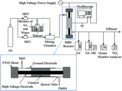
The experimental setup for catalytic decomposition of toluene in IPC is presented in Fig. 1. The plasma-catalytic system consisted of the gas supply system, the dielectric barrier discharge (DBD) reactor, the high voltage power supply as well as the gas analysis system. The gaseous toluene was obtained with a bubbler, which was diluted with pure air (99.999%, Jingong, Hangzhou). The mass flow controller (MFC, Sevenstars D08-3F) was used to maintain the gas flow rate constant during the test (i.e., 0.5 L min−1). The initial concentration of toluene was 210 ppm. The DBD reactor is illustrated detailedly in Fig. 1. An aluminium foil (40 mm long) wrapped around a cylindrical quartz tube (10 mm outer diameter and 0.8 mm wall thickness, respectively), which was used as the ground electrode. A coaxial stainless steel rod (3.5 mm diameter) served as the high voltage electrode. The catalyst (0.2 g) was packed into the gap between the stainless steel rod and quartz wall (approx. 80% volume fraction of the whole discharge zone) and a pair of polytetrafluoroethylene (PTFE) heads were used to seal the plasma reactor.The high voltage power supply (CTP-2000K) connected with the DBD reactor was used to generate the plasma discharge. The electrical signals were recorded using the oscilloscope (MDO 3034). The discharge powers of DBD reactor were calculated by a Q-U Lissajous method, and the specific input energy (SIE) could be calculated as follows:
| SIE (J L−1) = P/Q × 60, | (1) |
The analysis of outlet gas samples was continuously performed by gas chromatography (GC, GC9790 Plus, Fuli) equipped with two flame ionization detectors. One was connected to a nickel conversion furnace for measuring the methane, which was converted from carbon dioxide and carbon monoxide, and the other one was used for toluene measurement. The concentrations of O3 in the effluent were determined by an ozone monitor (Models 106-MH). The concentrations of NOx were measured by a NOx analyzer (Testo 350XL). The analysis of organic by-products in the effluent was performed with gas chromatography with mass spectrometry (GC-MS, Agilent 7890A GC/5957 MS). To ensure the reliability of tests, the plasma-catalytic system was run for 30 min before measurements until a steady state of effluent compositions was achieved.
The toluene decomposition efficiency (ηtoluene), selectivity of CO2 (SCO2), carbon balance (SCOx) and energy efficiency (ηenergy) could be calculated as:
| ηtoluene (%) = (cinlet − coutlet)/cinlet × 100% | (2) |
| SCO2 (%) = cCO2/[7 × (cinlet − coutlet)] × 100% | (3) |
| SCOx (%) = (cCO2 + cCO)/[7 × (cinlet − coutlet)] × 100% | (4) |
| ηenergy (g kW h−1) = 3.6 × M × cinlet × ηtoluene/(SIE × 24.04), | (5) |
Results and discussion
Plasma-catalytic performance of Co–Ce catalysts
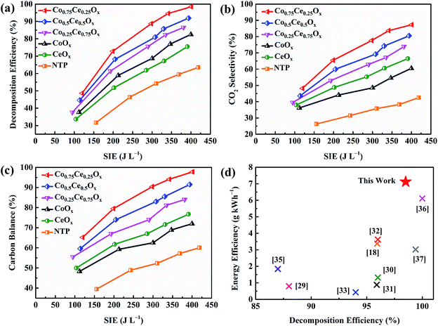
The catalytic activity of Co–Ce binary metal oxide catalysts towards toluene oxidation in IPC is evaluated. As presented in Fig. 2a, the toluene removal efficiency increases monotonically with enlarging the SIE. The higher SIE can reinforce the electric field strength in the discharge region, thus generating more highly energetic electrons and active particles to accelerate the reactions.27 Compared with NTP system, the introduction of catalysts remarkably improves the toluene decomposition efficiency (by 35.0%), indicating the strong plasma–catalyst interaction. More importantly, the removal efficiency of Co–Ce binary metal oxide catalysts is much higher than those of monometallic counterparts. To be specific, the decomposition efficiencies of Co0.75Ce0.25Ox, Co0.5Ce0.5Ox and Co0.25Ce0.75Ox are 98.5% (at 401 J L−1), 91.9% (at 394 J L−1) and 86.5% (at 381 J L−1), respectively, superior to those of CeOx (75.5% at 391 J L−1) and CoOx (82.5% at 400 J L−1), demonstrating an optimum catalytic performance when using the Co0.75Ce0.25Ox catalyst. The excellent toluene oxidation can be further validated by the lowest O3 concentration (81 ppm at 401 J L−1) with the Co0.75Ce0.25Ox catalyst (Fig. S1a†).The reaction rate of toluene oxidizing with atomic oxygen (7.6 × 10⁻¹⁴ cm3 per molecule per s) is much higher than that with O3 counterpart (3.9 × 10⁻²² cm3 per molecule per s).28 Thus, the high conversion efficiency of O3 to atomic oxygen is beneficial for superior toluene oxidation performance. Besides, the concentration of NOx is also measured (Fig. S1b†), in which the lowest NO2 content (19 ppm at 401 J L−1) is recognized when using the Co0.75Ce0.25Ox catalyst.
In addition to the efficient decomposition, the complete conversion of toluene to COx, especially CO2, is also highly desired. As presented in Fig. 2b and c, coupling the NTP with Co–Ce catalysts significantly improves the CO2 selectivity (by 44.8%) and carbon balance (by 37.7%). Among the catalysts, Co0.75Ce0.25Ox catalyst exhibits the optimum CO2 selectivity of 87.3% and carbon balance of 97.8% at 401 J L−1, demonstrating a high degree of toluene conversion to CO2 and COx. The durability and reusability of Co0.75Ce0.25Ox catalyst are further measured at 298 J L−1. The catalytic performance of Co0.75Ce0.25Ox catalyst decreases slightly after 12 h test (Fig. S2a†), demonstrating the excellent durability to resist deactivation. Moreover, the Co0.75Ce0.25Ox catalyst could be reused for 5 times with slight activity loss (less than 4%, Fig. S2b†), exhibiting a superior reusability.
A comparison of plasma-catalytic performance with respect to toluene decomposition efficiency and energy efficiency (i.e., the electrical energy input for per unit mass of VOCs) between this work and previous studies is conducted (Fig. 2d). Detailed boundary conditions of different catalytic systems for comparison are available in Table S1.† Using binary metal oxide catalyst of Co0.75Ce0.25Ox, this work simultaneously realizes enhanced toluene conversion (decomposition efficiency of 98.5%) and high energy efficiency of 7.12 g kW h−1, superior to those in the state-of-art literatures (0.42 to 6.11 g kW h−1).18,29–37
Structure and redox properties of catalysts
The outstanding plasma-catalytic performance can be interpreted by the synergistic effect between Co and Ce species and obvious plasma–catalyst interaction. A comprehensive characterization on the structure and redox property of Co–Ce catalysts is thus carried out. According to the XRD patterns in Fig. 3a, Co–Ce binary metal oxide catalysts are composed of spinel phase of Co3O4 (JCPDS 43-1003) and fluorite structure of CeO2 (JCPDS 34-0394). In particular, the characteristic peak of CeO2 (111) crystal face in the Co–Ce binary metal oxide catalysts slightly shifts to higher Bragg angle region, i.e., from 28.7° of CeO2 to 28.95° of Co–Ce catalysts (Fig. 3b). This phenomenon is primarily stimulated by the incorporation of Co cations into CeO2 fluorite lattice, leading to the formation of Co–Ce solid solution. When Ce4+ (0.097 nm in ionic radius) is replaced by Co3+ (0.065 nm) and Co2+ (0.082 nm), a contraction of CeO2 lattice occurs, thus developing plenty of defects in the lattice (Fig. 3c). These defects can increase the oxygen vacancies and contribute to the generation of surface oxygen species for improved catalytic activity.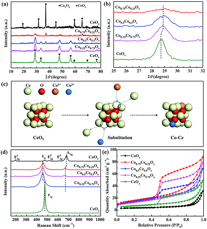 | ||
| Fig. 3 (a) Angle patterns and (b) enlarged zone patterns from XRD analysis. (c) Schematic diagram of Co–Ce solid solution. (d) Raman spectra and (e) N2 adsorption–desorption isotherms. | ||
The structural deformation in the crystallite lattice of Co–Ce catalysts can also be demonstrated by the Raman spectra. As shown in Fig. 3d, CeOx shows a characteristic F2g band of CeO2 cubic fluorite structure at around 471.6 cm−1![[thin space (1/6-em)]](https://www.rsc.org/images/entities/char_2009.gif) 38 and CoOx presents five characteristic peaks of Co3O4 spinel phase distinguished as F12g, Eg, F22g, F32g and A1g.39 In comparison with CeOx, the peak of F2g bands in the binary metal oxide catalyst shifts to lower frequency (452.3 cm−1), confirming the incorporation of Co cations into the CeO2 fluorite lattice and the deformation of lattice framework.40 Similar phenomenon is recognized on the A1g bands of Co–Ce catalysts, highlighting the obvious Co–Ce interaction.
38 and CoOx presents five characteristic peaks of Co3O4 spinel phase distinguished as F12g, Eg, F22g, F32g and A1g.39 In comparison with CeOx, the peak of F2g bands in the binary metal oxide catalyst shifts to lower frequency (452.3 cm−1), confirming the incorporation of Co cations into the CeO2 fluorite lattice and the deformation of lattice framework.40 Similar phenomenon is recognized on the A1g bands of Co–Ce catalysts, highlighting the obvious Co–Ce interaction.
Moreover, the characteristic diffraction peaks of Co–Ce oxides are much broader and weaker than those of monometallic counterparts (Fig. 3a), implying the decrease of crystallite size in the catalyst. To quantitatively characterize the catalyst structure, the CeO2 crystallite size in Co–Ce catalysts is calculated by the Scherrer's equation:41
d = 0.89λ/(β![[thin space (1/6-em)]](https://www.rsc.org/images/entities/char_2009.gif) cos cos![[thin space (1/6-em)]](https://www.rsc.org/images/entities/char_2009.gif) θ), θ),
| (6) |
As presented in Fig. 3e, N2 adsorption–desorption isotherms are further carried out to quantify the catalyst structure. Based on this, the specific surface area, total pore volume and average pore size of samples can be calculated (Table S2†). The specific surface area of Co–Ce binary metal oxide catalysts (46.0–56.0 m2 g−1) is much larger than those of CoOx and CeOx (12.1 and 25.6 m2 g−1, respectively). Among Co–Ce catalysts, Co0.75Ce0.25Ox sample exhibits the largest specific surface area (56.0 m2 g−1), which is 3.6 folds greater than that of CoOx. The higher surface area can provide abundant active sites for efficient oxidation reaction, consistent with the as-obtained superior plasma-catalytic performance using Co0.75Ce0.25Ox catalyst.
XPS analysis is performed to unveil the oxidation state of catalyst surface species, which plays a crucial role in determining the oxygen vacancies and oxygen mobility for reaction.15,42 Two peaks located at 779.8 and 795.0 eV are recognized (Fig. 4a), indexed to Co 2p3/2 and Co 2p1/2, respectively. The spin–orbit splitting within Co 2p peaks (15.2 eV) reveals that Co3O4 is the primary phase of cobalt oxides in the catalyst,26 in good accordance with XRD results. As shown in Fig. 4b, the Ce 3d spectra are deconvolved into eight peaks, in which the spin–orbit components of Ce 3d5/2 and Ce 3d3/2 are denoted by U and V, respectively. Ratios of Ce3+/(Ce3+ + Ce4+) are calculated by integrating the peak area (Table S3†). The content of Ce3+ increases with incorporating the Co species, which are estimated to be 12.7%, 16.2% and 19.2% for Co0.25Ce0.75Ox, Co0.5Ce0.5Ox and Co0.75Ce0.25Ox samples, respectively. The higher Ce3+ content is able to generate abundant defects in the CeO2 lattice,43,44 which facilitates more oxygen vacancies over catalyst surface and adsorption centers for active oxygen species, thus boosting the toluene conversion reaction.
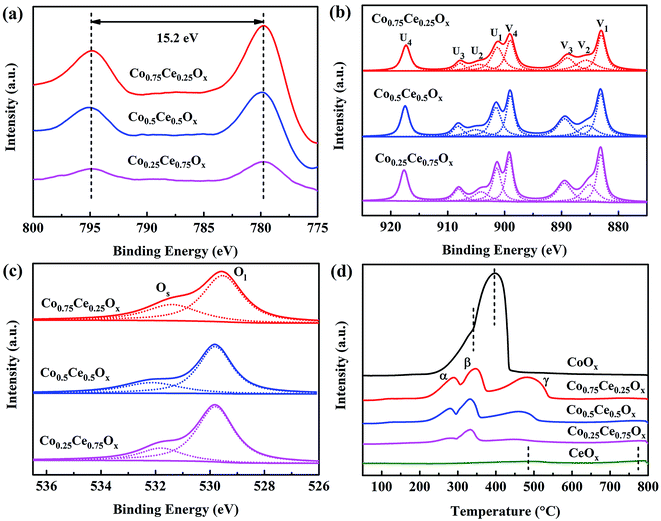 | ||
| Fig. 4 (a) Co 2p, (b) Ce 3d and (c) O 1s spectra of XPS analysis. (d) H2-TPR profiles of Co–Ce binary metal oxide catalysts. | ||
As shown in Fig. 4c, O 1s spectra are fitted into two peaks. The peaks at around 532.0 and 529.8 eV can be identified as the surface absorbed oxygen species (labeled by Os) and lattice oxygen (labeled by Ol), respectively.44,45 With increasing the amount of Co dopant, the ratio of Os/(Os + Ol) increases remarkably from 20.6% to 31.0% (Table S3†). In consideration of the high mobility of Os, the larger ratio of Os/(Os + Ol) is beneficial for yielding improved catalytic activity. As expected, Co0.75Ce0.25Ox catalyst exhibits the highest Ce3+ and Os concentration, agreeing well with the catalytic performance.
H2-TPR tests are carried out to evaluate the reducibility of catalysts. CeOx sample exhibits two broad peaks at 483.6 and 773.9 °C,46 and CoOx presents a distinct peak at 395.9 °C with a small shoulder of 341.4 °C![[thin space (1/6-em)]](https://www.rsc.org/images/entities/char_2009.gif) 47 (Fig. 4d). As for the Co–Ce composite, three peaks labeled as α (285.6 °C), β (344.3 °C) and γ (484.7 °C) are recognized. The α peak stems from the reduction of Co3+ to Co2+ cations while β and γ peaks are predominantly correlated with the reduction of Co2+ to Co in the Co3O4 phase and solid solution of Co–Ce, respectively.42 The temperature of α peak in the Co–Ce catalyst (285.6 °C) is obviously lower than those of CoOx (341.4 °C) and CeOx (483.6 °C), indicating the improved reducibility. This phenomenon is associated with the smaller crystallite size of Co–Ce samples, which promotes the formation of easily reducible sites and improved oxygen mobility for efficient toluene conversation. Detailed characterizations on the structure and redox property of used Co0.75Ce0.25Ox catalyst after plasma catalysis are available in Fig. S3, Tables S2 and S3.† It is found that the plasma-catalytic reaction exhibits a negative impact on the structure and redox property of the Co0.75Ce0.25Ox catalyst, which is mainly ascribed to the accumulation of intermediates on the catalyst surface,17 the partly oxidation from Ce3+ to Ce4+
47 (Fig. 4d). As for the Co–Ce composite, three peaks labeled as α (285.6 °C), β (344.3 °C) and γ (484.7 °C) are recognized. The α peak stems from the reduction of Co3+ to Co2+ cations while β and γ peaks are predominantly correlated with the reduction of Co2+ to Co in the Co3O4 phase and solid solution of Co–Ce, respectively.42 The temperature of α peak in the Co–Ce catalyst (285.6 °C) is obviously lower than those of CoOx (341.4 °C) and CeOx (483.6 °C), indicating the improved reducibility. This phenomenon is associated with the smaller crystallite size of Co–Ce samples, which promotes the formation of easily reducible sites and improved oxygen mobility for efficient toluene conversation. Detailed characterizations on the structure and redox property of used Co0.75Ce0.25Ox catalyst after plasma catalysis are available in Fig. S3, Tables S2 and S3.† It is found that the plasma-catalytic reaction exhibits a negative impact on the structure and redox property of the Co0.75Ce0.25Ox catalyst, which is mainly ascribed to the accumulation of intermediates on the catalyst surface,17 the partly oxidation from Ce3+ to Ce4+![[thin space (1/6-em)]](https://www.rsc.org/images/entities/char_2009.gif) 48 and the consumption of Os during the toluene decomposition.49
48 and the consumption of Os during the toluene decomposition.49
Plasma–catalyst interaction
In IPC, catalysts are integrated in the discharge region, which will affect the discharge behavior and thus determine the catalytic activity.50–52 Fig. 5a and b show the electrical signals within the NTP and IPC (using the Co0.75Ce0.25Ox catalyst at 250 J L−1). A typical filamentary discharge is observed for the NTP system, exhibiting obvious discharge current pulses in the waveform. Importantly, introducing catalyst into the discharge zone of the NTP noticeably affects the discharge behavior. On one hand, the presence of catalyst suppresses the current amplitude. The filamentary discharge can only be generated in the small void gap between catalyst particles and quartz wall. As a consequence, the packed catalysts in the NTP will reduce the available discharge volume, thus decreasing the current amplitude of filamentary discharge. On the other hand, the integration of catalyst markedly increases the amount of current pulses, which is predominantly attributed to the surface discharge generated over the catalyst surface. As schematically shown in Fig. 5c, the discharge mode is changed from the filamentary discharge (NTP) to the combined filamentary discharge and surface discharge (IPC), implying the enhanced ionization travelling along the catalyst surface for advanced catalytic reaction.53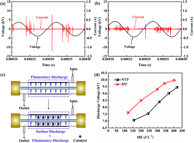 | ||
| Fig. 5 Electrical signals in (a) NTP and (b) IPC. (c) Schematic diagram of discharge behavior. (d) Discharge voltages within the NTP and IPC. | ||
The discharge voltage in the NTP and IPC system is also measured and compared. As presented in Fig. 5d, the magnitude of discharge voltage increases with enlarging the SIE. Importantly, the integration of catalysts can obviously extend the voltage amplitude (by > 0.5 kV), e.g., from 9.45 kV at 419 J L−1 to 9.97 kV at 401 J L−1. Enhanced electric field strength in the DBD reactor will produce more highly energetic electrons for accelerating the plasma-catalytic oxidation, demonstrating the significance of plasma–catalyst interaction in boosting the catalytic performance.
Mechanism of plasma-catalytic reaction
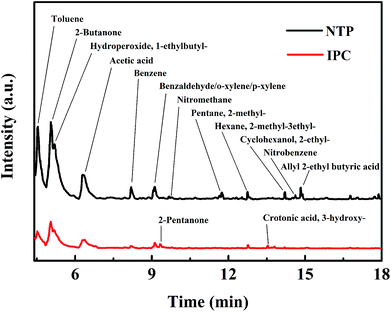
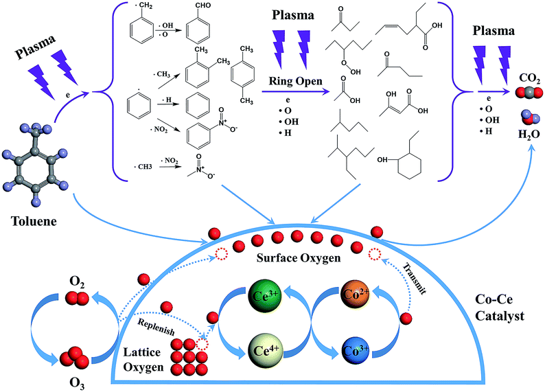
In order to reveal the reaction mechanism and pathways, the by-products in the outlet of the NTP and IPC system over the Co0.75Ce0.25Ox catalyst are measured by GC-MS (Fig. 6). Large amounts of toluene and organic intermediates, e.g., aldehydes, hydrocarbons, acids and benzene series, are observed after NTP system treated. While types and amounts of by-products significantly decrease in IPC, in good accordance with the efficient toluene conversion.The toluene decomposition process in IPC system can be identified into two parts:12,18 the gas-phase plasma reactions and the catalytic reactions on catalyst surface. According to GC-MS analysis, the reaction pathways of toluene degradation in gas phase are presented (Fig. 7).
The dissociation energy of C–H (methyl group), C–H (aromatic ring), C–C (methyl group-aromatic ring), C–C (aromatic ring) and C![[double bond, length as m-dash]](https://www.rsc.org/images/entities/char_e001.gif) C (aromatic ring) are 3.7 eV, 4.3 eV, 4.4 eV, 5.0–5.3 eV and 5.5 eV, respectively.54,55 In NTP system, the energy of highly energetic electrons reaches up to 10 eV. Therefore, these chemical bonds can be destroyed by electrons. The destruction of C–H within methyl group might be primary process of plasma reactions due to the lowest dissociation energy, resulting in the generation of benzyl radicals. After that, the formed benzyl radicals further react with oxygen species (·O and ·OH) from plasma discharge to produce benzaldehyde, as demonstrated in GC-MS results.
C (aromatic ring) are 3.7 eV, 4.3 eV, 4.4 eV, 5.0–5.3 eV and 5.5 eV, respectively.54,55 In NTP system, the energy of highly energetic electrons reaches up to 10 eV. Therefore, these chemical bonds can be destroyed by electrons. The destruction of C–H within methyl group might be primary process of plasma reactions due to the lowest dissociation energy, resulting in the generation of benzyl radicals. After that, the formed benzyl radicals further react with oxygen species (·O and ·OH) from plasma discharge to produce benzaldehyde, as demonstrated in GC-MS results.
Moreover, methyl and phenyl radicals can also be generated from the breaking of C–C connecting the methyl group with the aromatic ring. The reaction between methyl radicals and ·NO2 contributes to the formation of nitromethane. Phenyl radicals could react with ·CH3, ·H and ·NO2 to produce o-xylene/p-xylene, benzene and nitrobenzene. Subsequently, the aromatic intermediates are attacked by highly energetic electrons (>5.5 eV) and active species in the plasma to produce ring-opening intermediates, which are finally decomposed to CO2 and H2O. Noteworthy, the introduction of Co–Ce binary metal oxide catalysts into the NTP system can yield stronger electric field and more highly energetic electrons to improve the catalytic activity.
Additionally, toluene and organic intermediates are also adsorbed on the surface of Co–Ce catalysts placed in the discharge region, which are further decomposed by surface active oxygen species (Fig. 7). On one hand, the surface active oxygen species are generated from adsorbed oxygen molecules attacked by highly energetic electrons (eqn (7)) and O3 conversion reaction on catalyst surface (eqn (8) and (9)):56,57
| O2 + e → O + O | (7) |
| O3 + * → O* + O2 | (8) |
 | (9) |
| Ce3+/Ce4+ ⇌ Co2+/Co3+ | (10) |
During the catalytic reactions on the surface of catalysts, active oxygen species are consumed by decomposition of absorbed organic molecules, meanwhile the Co3+ sites are reduced to Co2+. The redox pair of Ce3+/Ce4+ in CeO2 facilitates the storage and release of lattice oxygen species, re-oxidizing Co2+ to Co3+. This redox cycle of Co2+/Co3+ is able to transmit the oxygen species to the surface of catalysts, thereby supplying the consumed surface active oxygen species. Additionally, the oxygen vacancies generated from lattice oxygen consumption via Co–Ce redox cycle can be replenished by gas phase oxygen species. Therefore, the synergistic effect between Co and Ce species promotes the generation and mobility of active surface oxygen species for superior catalytic performance.
Conclusion
This work investigated the catalytic performance of toluene decomposition over Co–Ce binary metal oxide catalysts in IPC. In comparison with the NTP system, the integration of Co–Ce catalysts significantly advances the toluene removal efficiency (by 35.0%), CO2 selectivity (by 44.8%) and carbon balance (by 37.7%). Among the catalysts, the Co–Ce binary metal oxide catalysts present better catalytic activity than those of monometallic counterparts. Especially, Co0.75Ce0.25Ox simultaneously realizes high-performance toluene conversion (decomposition efficiency of 98.5%, CO2 selectivity of 87.3% and carbon balance of 97.8% at 401 J L−1) and large energy efficiency of 7.12 g kW h−1, which is obviously higher than or comparable to those in the state-of-art literatures (0.42 to 6.11 g kW h−1). The excellent catalytic performance could be attributed to the synergistic effect between Co and Ce species and crucial plasma–catalyst interaction. On one hand, structural characterizations including XRD, Raman, N2 adsorption–desorption, XPS and H2-TPR reveal that the collaborative interactions can decrease the catalyst crystallite size (by 32.4%), enlarge the specific surface area (by 3.6 times), enhance the amount of oxygen vacancies/mobility (6.5% and 10.4% increase in the Ce3+ and Os concentration, respectively). These features are able to provide more active adsorption centers for the surface oxygen species and thus accelerate the toluene decomposition reactions. On the other hand, the plasma–catalyst interaction can reinforce the discharge voltage in the DBD reactor (by > 0.50 kV) and transform the discharge mode from filamentary discharge to the combined filamentary discharge and surface discharge, yielding improved catalytic reactions. In the end, based on the GC-MS observations, the plasma-catalytic reaction mechanism and pathways of toluene decomposition are demonstrated. The as-obtained insights open an alternative way of employing Co–Ce binary metal oxide catalysts to realize enhanced toluene conversion with high energy efficiency in the plasma catalysis.Conflicts of interest
There are no conflicts to declare.Acknowledgements
The authors acknowledge the financial support from the National Natural Science Foundation of China (No. 51576175), the Zhejiang Provincial Natural Science Foundation of China (No. LR17E060002) and the Fundamental Research Funds for the Central Universities (No. 2018XZZX002-17).References
- H. H. Kim, Y. Teramoto, N. Negishi and A. Ogata, Catal. Today, 2015, 256, 13–22 CAS.
- S. Veerapandian, C. Leys, N. De Geyter and R. Morent, Catalysts, 2017, 7, 113 CrossRef.
- E. C. Neyts, K. K. Ostrikov, M. K. Sunkara and A. Bogaerts, Chem. Rev., 2015, 115, 13408–13446 CrossRef CAS PubMed.
- X. X. Feng, H. X. Liu, C. He, Z. X. Shen and T. B. Wang, Catal. Sci. Technol., 2018, 8, 936–954 CAS.
- J. C. Whitehead, J. Phys. D: Appl. Phys., 2016, 49, 243001 CrossRef.
- J. Van Durme, J. Dewulf, C. Leys and H. Van Langenhove, Appl. Catal., B, 2008, 78, 324–333 CrossRef CAS.
- H. L. Chen, H. M. Lee, S. H. Chen, M. B. Chang, S. J. Yu and S. N. Li, Environ. Sci. Technol., 2009, 43, 2216–2227 CrossRef CAS PubMed.
- H. H. Kim, Y. Teramoto, A. Ogata, H. Takagi and T. Nanba, Plasma Chem. Plasma Process., 2015, 36, 45–72 Search PubMed.
- H. H. Kim, S. M. Oh, A. Ogata and S. Futamura, Appl. Catal., B, 2005, 56, 213–220 CAS.
- C. Ayrault, J. Barrault, N. Blin-Simiand, F. Jorand, S. Pasquiers, A. Rousseau and J. M. Tatibouët, Catal. Today, 2004, 89, 75–81 CrossRef CAS.
- X. B. Zhu, X. Gao, X. N. Yu, C. H. Zheng and X. Tu, Catal. Today, 2015, 256, 108–114 CrossRef CAS.
- M. J. Lu, R. Huang, P. T. Wang, L. M. Chen, J. L. Wu, M. L. Fu, W. Wen, B. C. Huang and D. Q. Ye, Plasma Chem. Plasma Process., 2014, 34, 1141–1156 CrossRef CAS.
- C. He, L. Cao, X. Liu, W. Fu and J. Zhao, Int. J. Environ. Sci. Technol., 2015, 12, 3531–3540 CrossRef CAS.
- J. L. Wu, Y. X. Huang, Q. B. Xia and Z. Li, Plasma Chem. Plasma Process., 2013, 33, 1073–1082 CrossRef CAS.
- N. Jiang, J. Hu, J. Li, K. F. Shang, N. Lu and Y. Wu, Appl. Catal., B, 2016, 184, 355–363 CrossRef CAS.
- H. Song, F. Hu, Y. Peng, K. Li, S. Bai and J. Li, Chem. Eng. J., 2018, 347, 447–454 CrossRef CAS.
- X. B. Zhu, X. Gao, R. Qin, Y. X. Zeng, R. Y. Qu, C. H. Zheng and X. Tu, Appl. Catal., B, 2015, 170–171, 293–300 CrossRef CAS.
- B. W. Wang, C. M. Chi, M. Xu, C. Wang and D. Meng, Chem. Eng. J., 2017, 322, 679–692 CrossRef CAS.
- Z. Bo, M. Yuan, S. Mao, X. Chen, J. H. Yan and K. F. Cen, Sens. Actuators, B, 2018, 256, 1011–1020 CrossRef CAS.
- Z. Bo, W. G. Zhu, W. Ma, Z. H. Wen, X. R. Shuai, J. H. Chen, J. H. Yan, Z. H. Wang, K. F. Cen and X. L. Feng, Adv. Mater., 2013, 25, 5799–5806 CrossRef CAS PubMed.
- Z. Bo, S. Mao, Z. J. Han, K. Cen, J. Chen and K. K. Ostrikov, Chem. Soc. Rev., 2015, 44, 2108–2121 RSC.
- A. Rokicińska, P. Natkański, B. Dudek, M. Drozdek, L. Lityńska-Dobrzyńska and P. Kuśtrowski, Appl. Catal., B, 2016, 195, 59–68 CrossRef.
- A. Białas, M. Mazur, P. Natkański, B. Dudek, M. Kozak, A. Wach and P. Kuśtrowski, Appl. Surf. Sci., 2016, 362, 297–303 CrossRef.
- Z. M. Li, X. L. Guo, F. Tao and R. X. Zhou, RSC Adv., 2018, 8, 25283–25291 RSC.
- C. Wang, C. H. Zhang, W. C. Hua, Y. L. Guo, G. Z. Lu, S. Gil and A. Giroir-Fendler, Chem. Eng. J., 2017, 315, 392–402 CrossRef CAS.
- S. Akram, Z. Wang, L. Chen, Q. Wang, G. L. Shen, N. Han, Y. F. Chen and G. L. Ge, Catal. Commun., 2016, 73, 123–127 CrossRef CAS.
- W. Abou Saoud, A. A. Assadi, M. Guiza, A. Bouzaza, W. Aboussaoud, A. Ouederni, I. Soutrel, D. Wolbert and S. Rtimi, Appl. Catal., B, 2017, 213, 53–61 CrossRef CAS.
- J. Van Durme, J. Dewulf, W. Sysmans, C. Leys and H. Van Langenhove, Chemosphere, 2007, 68, 1821–1829 CrossRef CAS PubMed.
- X. X. Xu, P. T. Wang, W. C. Xu, J. L. Wu, L. M. Chen, M. L. Fu and D. Q. Ye, Chem. Eng. J., 2016, 283, 276–284 CrossRef CAS.
- Y. F. Guo, D. Q. Ye and K. F. Chen, Plasma Chem. Plasma Process., 2006, 26, 237–249 CrossRef CAS.
- Y. F. Guo, D. Q. Ye, K. F. Chen, J. C. He and W. L. Chen, J. Mol. Catal. A: Chem., 2006, 245, 93–100 CrossRef CAS.
- T. Zhu, J. Li, W. Liang and Y. Jin, J. Hazard. Mater., 2009, 165, 1258–1260 CrossRef CAS PubMed.
- H. B. Huang, D. Q. Ye, D. Y. C. Leung, F. D. Feng and X. J. Guan, J. Mol. Catal. A: Chem., 2011, 336, 87–93 CrossRef CAS.
- H. T. Quoc An, T. Pham Huu, T. Le Van, J. M. Cormier and A. Khacef, Catal. Today, 2011, 176, 474–477 CrossRef CAS.
- H. T. Quoc An, T. Pham Huu, T. Le Van, J. M. Cormier and A. Khacef, Catal. Today, 2011, 176, 474–477 CrossRef CAS.
- X. X. Xu, J. L. Wu, W. C. Xu, M. L. He, M. L. Fu, L. M. Chen, A. M. Zhu and D. Q. Ye, Catal. Today, 2017, 281, 527–533 CrossRef CAS.
- X. Yao, J. Zhang, X. Liang and C. Long, Chemosphere, 2018, 208, 922–930 CrossRef CAS PubMed.
- M. Fernández-García, A. Martínez-Arias, A. Iglesias-Juez, C. Belver, A. B. Hungría, J. C. Conesa and J. Soria, J. Catal., 2000, 194, 385–392 Search PubMed.
- A. Buenolopez, I. Suchbasanez and C. Salinasmartinezdelecea, J. Catal., 2006, 244, 102–112 CrossRef CAS.
- J. E. Spanier, R. D. Robinson, F. Zhang, S. W. Chan and I. P. Herman, Phys. Rev. B: Condens. Matter Mater. Phys., 2001, 64, 245407 CrossRef.
- X. Tu, H. J. Gallon and J. C. Whitehead, Catal. Today, 2013, 211, 120–125 CrossRef CAS.
- J. N. Xu, G. Z. Lu, Y. Guo, Y. L. Guo and X. Q. Gong, Appl. Catal., A, 2017, 535, 1–8 CrossRef CAS.
- S. Gil, J. Garcia-Vargas, L. Liotta, G. Pantaleo, M. Ousmane, L. Retailleau and A. Giroir-Fendler, Catalysts, 2015, 5, 671–689 CrossRef CAS.
- G. L. Zhou, H. Lan, T. T. Gao and H. M. Xie, Chem. Eng. J., 2014, 246, 53–63 CrossRef CAS.
- T. Cai, H. Huang, W. Deng, Q. G. Dai, W. Liu and X. Y. Wang, Appl. Catal., B, 2015, 166–167, 393–405 CrossRef CAS.
- W. J. Hong, S. Iwamoto, S. Hosokawa, K. Wada, H. Kanai and M. Inoue, J. Catal., 2011, 277, 208–216 CAS.
- Z. P. Qu, K. Gao, Q. Fu and Y. Qin, Catal. Commun., 2014, 52, 31–35 CAS.
- W. J. Shan, M. Fleys, F. Lapicque, D. Swierczynski, A. Kiennemann, Y. Simon and P. M. Marquaire, Appl. Catal., A, 2006, 311, 24–33 CAS.
- X. B. Zeng, Y. Xu, B. Zhang, G. Q. Luo, P. Sun, R. J. Zou and H. Yao, Chem. Eng. J., 2017, 309, 503–512 CAS.
- D. H. Mei, X. B. Zhu, Y. L. He, J. D. Yan and X. Tu, Plasma Sources Sci. Technol., 2014, 24, 015011 Search PubMed.
- X. Tu, H. J. Gallon and J. C. Whitehead, J. Phys. D: Appl. Phys., 2011, 44, 482003 Search PubMed.
- X. Tu and J. C. Whitehead, Appl. Catal., B, 2012, 125, 439–448 CAS.
- H. H. Kim, J. H. Kim and A. Ogata, J. Phys. D: Appl. Phys., 2009, 42, 135210 Search PubMed.
- S. Y. Liu, D. H. Mei, L. Wang and X. Tu, Chem. Eng. J., 2017, 307, 793–802 CrossRef CAS.
- S. Y. Liu, D. H. Mei, M. A. Nahil, S. Gadkari, S. Gu, P. T. Williams and X. Tu, Fuel Process. Technol., 2017, 166, 269–275 CrossRef CAS.
- M. N. Lyulyukin, A. S. Besov and A. V. Vorontsov, Appl. Catal., B, 2016, 183, 18–27 CrossRef CAS.
- W. J. Liang, L. Ma, H. Liu and J. Li, Chemosphere, 2013, 92, 1390–1395 CrossRef CAS PubMed.
- X. B. Zhu, S. Y. Liu, Y. X. Cai, X. Gao, J. S. Zhou, C. H. Zheng and X. Tu, Appl. Catal., B, 2016, 183, 124–132 CrossRef CAS.
Footnote |
| † Electronic supplementary information (ESI) available. See DOI: 10.1039/c9ra00794f |
| This journal is © The Royal Society of Chemistry 2019 |

