 Open Access Article
Preparation of graphene/Au aerogel film through the hydrothermal process and application for H2O2 detection
Ting Shen,
Zhiyong Zhao,
Qishi Zhong,
Yujun Qin *,
Pu Zhang and
Zhi-Xin Guo
Department of Chemistry, Renmin University of China, Beijing 100872, China. E-mail: yjqin@ruc.edu.cn
First published on 29th April 2019
Abstract
In this paper, one-step preparation of graphene/gold nanoparticle hydrogel film through the hydrothermal method is reported. The hydrogel film could be formed on a glass substrate under hydrothermal conditions, and upon freeze-drying, the aerogel film of 40 μm thickness with satisfying flexibility and strength is obtained. The aerogel composite film is characterized by scanning/transmission electron microscopy, X-ray diffraction, Raman spectroscopy and X-ray photoelectron spectroscopy. Moreover, the aerogel film is directly used as the electrochemical electrode for sensing H2O2, and exhibits good performance with a broad linear range, low detection limit and excellent selectivity. This work provides a route for the fabrication of graphene film material with wide potential in various aspects.
Introduction
Graphene has gathered tremendous attention and in-depth research in various fields owing to its high surface area, excellent conductivity and high mechanical strength.1,2 Multiple graphene-based materials have been prepared for potential applications, such as energy storage and conversion,3,4 catalysis5 and electrochemical sensing.6 Electrochemical analysis is one of the most promising aspects of graphene's application, ascribed to the excellent electron transport property and high specific surface area. Graphene-involving non-enzyme electrochemical sensors have shown excellent performance in terms of sensitivity, durability and reproducibility.7,8 In general, graphene-based electrochemical sensors are fabricated by the modification of a glassy carbon electrode (GCE) with the graphene suspension, while the drop-drying method would inevitably bring about the restacking of the graphene sheets and influence the properties of the sensors. Recently, with the rising research of graphene aerogels,9–12 some efforts have been focused on the preparation of GCEs modified with graphene aerogels, which could utilize the superiority of the porous material and have exhibited dramatic electrochemical performance enhancement.13–15 The fabrication processes also usually involve the deposition of the aerogel suspension on GCEs. However, owing to the good mechanical strength of the graphene aerogel, the manipulation is usually difficult, even requiring the aid of ultrasonication or grinding pre-treatment. Besides, some untraditional methods were also utilized to prepare graphene-aerogel modified GCEs. For example, Zhu et al. fabricated a hemispheric graphene/Ag aerogel on a GCE16 and Tian et al. covered the GCE with a phosphorus-doped graphene aerogel disk,17 which both exhibited excellent performance in electrochemical sensing of hydrogen peroxide (H2O2).So far, most applications of graphene in electrochemical sensors are realized on GCEs, which involves a relatively tedious process of electrode pre-treatment and graphene dispersing/dropping/drying with accurate control and necessary consideration of adhesion and duration. One convenient alternative way is the direct use of graphene, especially 3D materials, as electrode sensors. For instance, Chen et al. prepared graphene foam by CVD method as an excellent electrochemical sensor for detection of dopamine.18 Wang et al. reported the direct use of nitrogen-doped graphene aerogel piece cut from the hydrothermally prepared aerogel as high-performance non-enzymatic sensor.19 We have reported the preparation of graphene/gold nanoparticle (GNP) aerogel under a mild condition as electrode for electrochemical sensing of H2O2.20
Hydrothermal process is a widely used and efficient method for converting the aqueous graphene oxide (GO) dispersion into reduced GO (rGO) hydrogel, which could subsequently yield rGO aerogel by freeze-drying treatment.21 Under the hydrothermal condition, the rGO sheets are interconnected owing to the strong π–π, hydrophobic and electrostatic interactions.22 The release of CO2 in the hydrothermal process endows the rGO framework with porous structure.23 In most cases, the as-prepared rGO aerogels are in the forms of 3D bulk or monolith.24 Actually, the graphene aerogel films have numerous potential applications, such as electronic materials,25,26 sensors,19,27 batteries/supercapacitors,18,28–30 and filter membranes.31,32 However, the thin aerogel films, are generally fabricated by peeling or grinding-casting from the bulky aerogels, and the quality of the final film is uncontrollable.
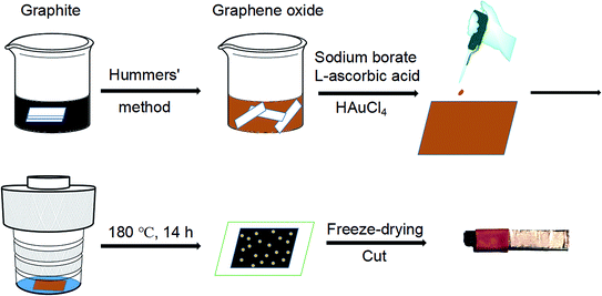
In this work, we report the facile preparation of graphene aerogel films through the hydrothermal method. In the autoclave, the mixed solution of GO, reductant and HAuCl4 is uniformly spreaded on a glass sheet and undergoes a hydrothermal process. The obtained rGO/GNP composite hydrogel is then freeze-dried to yield the rGO/GNP aerogel film, which could be cut and directly used as electrochemical electrode. The aerogel film sensor demonstrates satisfying electrocatalytic performances in the detection of H2O2.
Experimental
The reagents used in the experiment are all analytically pure and used without further purification. The natural graphite powder was purchased from Alfa Aesar. HAuCl4·4H2O and L-ascorbic acid (AA) were purchased from Sinopharm Chemical Reagent Beijing Co., Ltd. Other chemicals were purchased from Beijing Chemical Works. GO was prepared from graphite powder by a modified Hummers' method.33 Briefly, 5 mL of aqueous GO solution (6 mg mL−1, pH = 8.5, adjusted by NaOH) was mixed with 60 μL of aqueous solution of Na2B4O7 (5 mg mL−1) as an enhancer34 in a beaker. 90 mg of AA was added into the mixture with vigorous and continuous stirring. Afterwards, 200 μL of aqueous HAuCl4 solution (14.34 mg mL−1) was dropped into the solution. The composite aerogel was made by dropping and spreading 500 μL of the mixed solution on a glass sheet (2 cm × 2.3 cm). Then the glass sheet was put into a hydrothermal autoclave (50 mL) containing 1 mL of deionized water before heated at 180 °C for 14 h. Afterwards, the formed hydrogel film was freeze-dried under vacuum (−50 °C) to obtain the resulting rGO/GNP aerogel film (thickness ∼ 40 μm).35 Finally, the film was cut into pieces (2 mm × 3 mm) and connected with a conductive copper paste (wrapped tightly with insulating tape to prevent the contact with the solution) to make the electrode for electrochemical measurements. The preparation process of aerogel film and electrode is outlined in Scheme 1.Scanning electron microscopic (SEM) characterization was conducted on a Hitachi SU8010 with the accelerating voltage at 5 kV. Transmission electron microscopic (TEM) images were captured via a JEOL 2010 operating with the accelerating voltage at 200 kV. A Gatan model 780 CCD camera is used to confirm the sizes and dispersions of nanoparticles. X-ray diffraction (XRD) analysis was examined by Shimadzu XRD-7000 with Cu Kα radiation in the 2θ range from 5° to 80°, which had a scan rate of 2° min−1 at 40 kV and 30 mA. Raman spectra were obtained by a Horiba XploRA PLUS confocal microscope with 532 nm laser excitation. X-ray photoelectron spectroscopy (XPS) was investigated by a Kratos AXIS Ultra at 300 W Al kα radiation. The electrochemical analysis was conducted on a CHI660E electrochemical analyzer (Chenhua instruments, Shanghai) using a conventional three-electrode system composed by a platinum wire as the counter electrode, a KCl saturated Ag/AgCl electrode as the reference electrode and the aerogel film electrode with copper paste as working electrode.
Results and discussion
The preparation of the graphene hydrogel film refers to the traditional hydrothermal method except that small dose of GO solution (500 μL) on the glass sheet replaces the relatively large amount of solution (dozens of mL) in the autoclave. To create a hydrothermal condition and avoid the drying of GO solution, extra water is added around the glass sheet. During the hydrothermal process, the reduction of GO and Au3+ by AA occurs simultaneously to form the rGO/GNP hydrogel film on the glass. Just like the shrinkage of common graphene hydrogel, the area of the obtained rGO/GNP hydrogel film is about half of the precursor solution. Subsequent freeze-drying treatment produces the smooth aerogel composite film with the thickness of ∼40 μm. The rGO/GNP aerogel film possesses a satisfying tensile stress of 2.5 MPa, which facilitates the following manipulation and ensures its stability in application.The microstructure of the rGO/GNP aerogel film was investigated by SEM (Fig. 1a–c) and TEM (Fig. 1d). As seen from a rough review of the surface (Fig. 1a), the film demonstrates the smooth morphology with pores within the interconnected graphene sheets. In higher magnification of the side view (Fig. 1b), the porous graphene structure could be obviously observed, while the GNPs could hardly be seen. Fig. 1c clearly displays the homogeneously distributed GNPs on the graphene sheet. The GNPs exhibit the relatively large size of ∼40 nm, as shown in TEM of Fig. 1d, with the inset exhibiting the (111) planes of crystalline gold observed in the high resolution. The selected area electron diffraction (SEAD) shows typical reflexes of ordered regions of Au (Fig. 1d inset), which is consistent with the following XRD result.
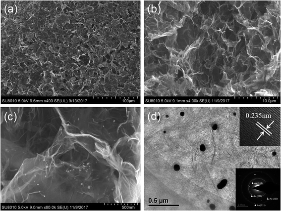 | ||
| Fig. 1 SEM images of the rGO/GNP aerogel at (a) front view and (b and c) side view. (d) TEM image of the rGO/GNP aerogel with the insets showing the (111) planes and SAED pattern of Au. | ||
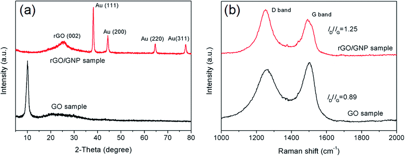
The rGO/GNP aerogel film was further characterized by XRD and Raman measurements. As seen in Fig. 2a, the XRD patterns of the aerogel film and pristine GO show distinct characteristics. Compared with the peak of GO sample at 10°, the graphene peak of rGO/GNP aerogel appears at 25.3°, indicating the stacking of graphene sheets owing to the reduction of GO to rGO. The peaks at 38.35°, 44.54°, 64.81° and 77.71° are assigned to face-centered cubic bulk Au (111), (200), (220) and (311), respectively, which match well with the standard values of Au (JCPDS 04-0784).36 The Raman spectra (Fig. 2b) of rGO/GNP and GO samples display the characteristic peaks at 1257 cm−1 and 1500 cm−1, which can be attributed to the D band and G band of graphene, respectively. The D band stands for the disordered structural defects and the G band represents the first-order scattering of the E2g mode observed for sp2 carbon domains. The intensity ratio of two bands (ID/IG) indicates the structural integrity of the graphene. Generally, the value of ID/IG would decrease after the reduction of GO due to removal of the oxygen-containing functional groups and the recovery of sp3 carbon. However, the ID/IG value of rGO/GNP aerogel increases to 1.25, much higher than 0.89 of GO sample. This phenomenon demonstrates the increasing of the disorder for the graphene carbon in the rGO/GNP sample, which could be ascribed to the breaking of graphene sheets into smaller pieces after reduction.35,37
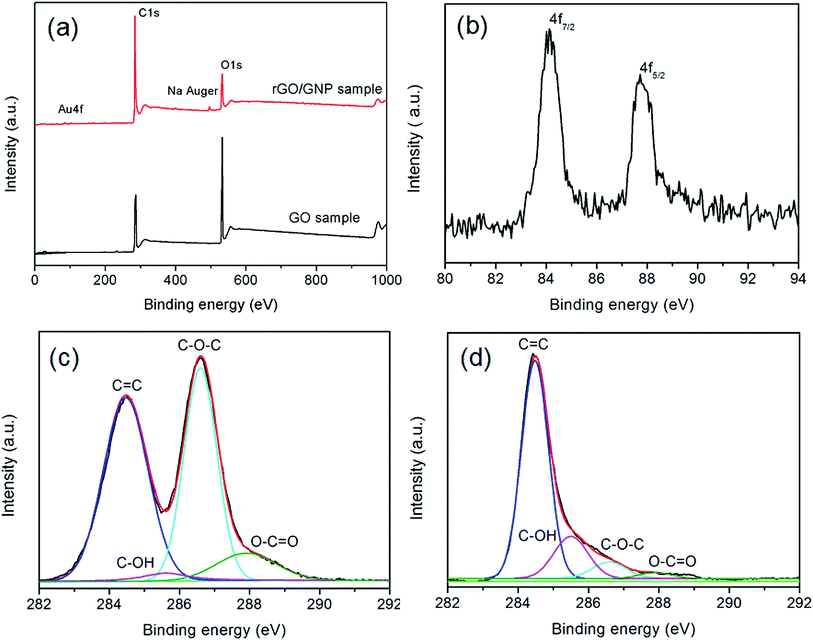
The XPS spectra of rGO/GNP and GO samples clearly demonstrate the variation of the compositions. As shown in Fig. 3a, both of the samples exhibit the features of C1s and O1s at the binding energies of 284 eV and 532 eV, respectively. The spectrum of rGO/GNP sample exhibits the peaks of Na Auger at 497 eV corresponding to the residual byproduct. The peak of Au could be divided into two peaks corresponding to Au4f7/2 and Au4f5/2 in the metallic state with the binding energies of 84.2 eV and 87.8 eV, respectively (Fig. 3b).38 The deconvoluted C1s spectra for GO and rGO/GNP samples are shown in Fig. 3c and d, respectively. The peak of 284.5 eV is ascribed to the C![[double bond, length as m-dash]](https://www.rsc.org/images/entities/char_e001.gif) C bonds and the peaks at 286.6 eV, 285.6 eV and 287.9 eV are assigned to C–O–C, C–OH and O–C
C bonds and the peaks at 286.6 eV, 285.6 eV and 287.9 eV are assigned to C–O–C, C–OH and O–C![[double bond, length as m-dash]](https://www.rsc.org/images/entities/char_e001.gif) O, respectively.39,40 Obviously, the peak intensity associated with oxygen-containing bonds dramatically decreases for the rGO/GNP aerogel compared with that for GO, indicating that GO in the aerogel is almost completely reduced.
O, respectively.39,40 Obviously, the peak intensity associated with oxygen-containing bonds dramatically decreases for the rGO/GNP aerogel compared with that for GO, indicating that GO in the aerogel is almost completely reduced.
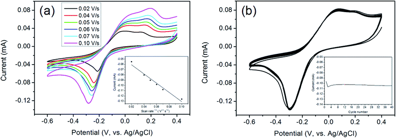
The aerogel film could be conveniently tailored owing to its good flexibility and strength. Herein the rGO/GNP film is utilized directly as the electrode for electrochemical analysis. The electrocatalytic performance of rGO/GNP electrode in detecting H2O2 in phosphate buffer solution (PBS, pH = 7) are investigated. As shown in Fig. 4a, the cyclic voltammograms (CVs) exhibit obvious redox couple peaks upon 0.5 mM H2O2, and the currents increase with the increase of the scan rate. The inset reveals that there is a linear relationship between the reduction current and the square root of the scan rate, which suggests the diffusion-controlled electrochemical process for the rGO/GNP aerogel electrode. In addition, to investigate the repeatability of rGO/GNP aerogel electrode, CV measurements are carried out at the scan rate of 0.1 V s−1 with the presence of 0.5 mM H2O2 for 40 cycles, as seen in Fig. 4b, and the inset shows the variation of the current along with the cycle number. Obviously, except the first two cycles for electrode activation, the current almost stays in a straight line with only 2% current loss at the end, which means the excellent repeatability of the rGO/GNP aerogel electrode.
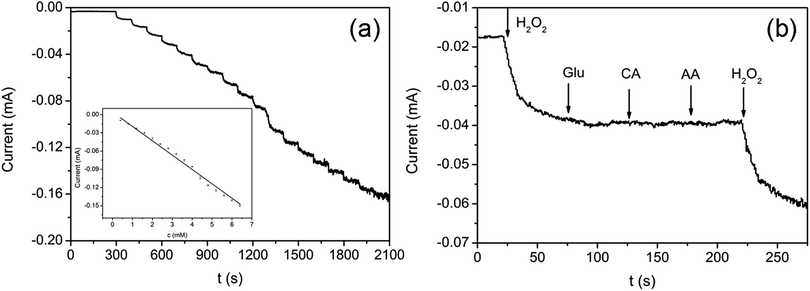
The typical current–time (I–t) plot of rGO/GNP electrode in PBS solution (pH = 7) on consecutive step change of H2O2 concentrations is shown in Fig. 5a. The instant increase of the reductive current responding to the stepwise dropping of H2O2 suggests the rapid amperometric response of the rGO/GNP electrode regarding H2O2. The inset demonstrates the calibration curve of the response current against the H2O2 concentration, which contains a broad linear range of 0.4–6.4 mM (R2 = 0.992) and a low detection limit of 12 μM according to 3Sb/S, in which 3 is signal-to-noise ratio, Sb is the standard deviation of the current response in the absence of H2O2 and S is the sensitivity.16,41 The sensitivity of the rGO/GNP electrode towards H2O2 is 2.4 × 10⁻² mA mM−1 according to the slope of the I–t calibration curve.
To investigate the anti-interference performance of the rGO/GNP sensor in detecting H2O2, several common interfering species including glucose (Glu), citric acid (CA) and AA are used in the I–t measurement at −0.3 V. As shown in Fig. 5b, with successive injection of H2O2 (1.2 mM) and three interfering species (Glu, CA, AA, 1.0 mM), the rGO/GNP electrode only presents obvious response to H2O2 and the current keeps steady upon the addition of the interfering species. Such satisfactory selectivity could be attributed to the low potential of −0.3 V used in the H2O2 detection and the uniform dispersion of GNPs in the composite aerogel film, which indicates that the aerogel sensor possesses potential for sensing H2O2 in practical application.
Conclusions
In this study, we report the development of hydrothermal method for the one-step preparation graphene hydrogel film. The subsequent freeze-drying process yields thin aerogel film that could be tailored for direct use of electrochemical electrode. The Au-decorated aerogel film sensor shows good behaviours in H2O2 detection, with a broad linear range at 0.4–6.4 mM, low detection limit of 12 μM and remarkable selectivity against common interfering species. Our work may provide new strategy for the preparation of graphene-based functional hydrogel/aerogel film materials, which could be used in various fields, such as sensor, catalysis and energy storage.Conflicts of interest
There are no conflicts to declare.Acknowledgements
This work was supported by the National Natural Science Foundation of China (Grant No. 21773305) and the Fundamental Research Funds for the Central Universities, the Research Funds of Renmin University of China (Grant No. 16XNLQ04).References
- A. K. Geim and K. S. Novoselov, Nat. Mater., 2007, 6, 183–191 CrossRef CAS PubMed.
- K. S. Novoselov, V. I. Fal'ko, L. Colombo, P. R. Gellert, M. G. Schwab and K. Kim, Nature, 2012, 490, 192–200 CrossRef CAS PubMed.
- L. W. Ji, P. Meduri, V. Agubra, X. C. Xiao and M. Alcoutlabi, Adv. Energy Mater., 2016, 6, 1502159 CrossRef.
- Y. Q. Sun, Q. O. Wu and G. Q. Shi, Energy Environ. Sci., 2011, 4, 1113–1132 RSC.
- B. F. Machado and P. Serp, Catal. Sci. Technol., 2012, 2, 54–75 RSC.
- Y. Y. Shao, J. Wang, H. Wu, J. Liu, I. A. Aksay and Y. H. Lin, Electroanalysis, 2010, 22, 1027–1036 CrossRef CAS.
- D. Y. Zheng, H. Hu, X. J. Liu and S. S. Hu, Curr. Opin. Colloid Interface Sci., 2015, 20, 383–405 CrossRef CAS.
- M. Zhou, Y. Zhai and S. Dong, Anal. Chem., 2009, 81, 5603–5613 CrossRef CAS PubMed.
- L. Jiang and Z. Fan, Nanoscale, 2014, 6, 1922–1945 RSC.
- Y. Shen, Q. L. Fang and B. L. Chen, Environ. Sci. Technol., 2015, 49, 67–84 CrossRef CAS PubMed.
- Y. Cheng, Y. Fan, Y. Pei and M. Qiao, Catal. Sci. Technol., 2015, 5, 3903–3916 RSC.
- C. Li and G. Q. Shi, Nanoscale, 2012, 4, 5549–5563 RSC.
- L. Chen, M. Feng and H. B. Zhan, RSC Adv., 2014, 4, 30689–30696 RSC.
- R. Y. Li, L. Liu, H. X. Bei and Z. J. Li, Biosens. Bioelectron., 2016, 79, 457–466 CrossRef CAS PubMed.
- R. Y. Li, F. C. Cui, H. Y. Zhu, X. L. Sun and Z. J. Li, Biosens. Bioelectron., 2018, 119, 156–162 CrossRef PubMed.
- X. H. Lou, C. L. Zhu, H. Pan, J. Ma, S. M. Zhu, D. Zhang and X. L. Jiang, Electrochim. Acta, 2016, 205, 70–76 CrossRef CAS.
- Y. Tian, Z. Wei, K. H. Zhang, S. Peng, X. Zhang, W. M. Liu and K. Chu, Sens. Actuators, B, 2017, 241, 584–591 CrossRef CAS.
- X. Dong, X. Wang, L. Wang, H. Song, H. Zhang, W. Huang and P. Chen, ACS Appl. Mater. Interfaces, 2012, 4, 3129–3133 CrossRef CAS PubMed.
- Z.-X. Cai, X.-H. Song, Y.-Y. Chen, Y.-R. Wang and X. Chen, Sens. Actuators, B, 2016, 222, 567–573 CrossRef CAS.
- X. L. Liu, T. Shen, Z. Y. Zhao, Y. J. Qin, P. Zhang, H. X. Luo and Z. X. Guo, Mater. Lett., 2018, 229, 368–371 CrossRef CAS.
- K. C. Wasalathilake, D. G. D. Galpaya, G. A. Ayoko and C. Yan, Carbon, 2018, 137, 282–290 CrossRef CAS.
- Y. X. Xu, K. X. Sheng, C. Li and G. Q. Shi, ACS Nano, 2010, 4, 4324–4330 CrossRef CAS PubMed.
- K. W. Hu, X. Y. Xie, T. Szkopek and M. Cerruti, Chem. Mater., 2016, 28, 1756–1768 CrossRef CAS.
- Z. Li, Z. Liu, H. Sun and C. Gao, Chem. Rev., 2015, 115, 7046–7117 CrossRef CAS PubMed.
- G. Eda, G. Fanchini and M. Chhowalla, Nat. Nanotechnol., 2008, 3, 270–274 CrossRef CAS PubMed.
- X. W. Yang, L. Qiu, C. Cheng, Y. Z. Wu, Z. F. Ma and D. Li, Angew. Chem., Int. Ed., 2011, 50, 7325–7328 CrossRef CAS PubMed.
- A. Kaur, J. Kaur and R. C. Singh, Sens. Actuators, A, 2018, 282, 97–113 CrossRef CAS.
- L. Zhang and G. Q. Shi, J. Phys. Chem. C, 2011, 115, 17206–17212 CrossRef CAS.
- S. Y. Lyu, Y. P. Chen, S. J. Han, L. M. Guo, Z. L. Chen, Y. Lu, Y. Chen, N. Yang and S. Q. Wang, RSC Adv., 2018, 8, 13191–13199 RSC.
- Y. Y. Lv, L. Li, Y. Zhou, M. Yu, J. Q. Wang, J. X. Liu, J. G. Zhou, Z. Q. Fan and Z. Q. Shao, RSC Adv., 2017, 7, 43512–43520 RSC.
- H. C. Bi, X. Xie, K. B. Yin, Y. L. Zhou, S. Wan, L. B. He, F. Xu, F. Banhart, L. T. Sun and R. S. Ruoff, Adv. Funct. Mater., 2012, 22, 4421–4425 CrossRef CAS.
- L. Zhang, H. Q. Li, X. J. Lai, X. J. Su, T. Liang and X. R. Zeng, Chem. Eng. J., 2017, 316, 736–743 CrossRef CAS.
- Z. Y. Sui, Y. Cui, J. H. Zhu and B. H. Han, ACS Appl. Mater. Interfaces, 2013, 5, 9172–9179 CrossRef CAS PubMed.
- X. Xu, Q. Zhang, Y. Yu, W. Chen, H. Hu and H. Li, Adv. Mater., 2016, 28, 9223–9230 CrossRef CAS PubMed.
- M. Zhang, X. Lu, H.-Y. Wang, X. Liu, Y. Qin, P. Zhang and Z.-X. Guo, RSC Adv., 2016, 6, 35945–35951 RSC.
- Y. Qin, R. C. Che, C. Y. Liang, J. Zhang and Z. W. Wen, J. Mater. Chem., 2011, 21, 3960–3965 RSC.
- S. Mutyala and J. Mathiyarasu, Mater. Sci. Eng., C, 2016, 69, 398–406 CrossRef CAS PubMed.
- B. S. Kong, J. Geng and H. T. Jung, Chem. Commun., 2009, 2174–2176 RSC.
- O. C. Compton, D. A. Dikin, K. W. Putz, L. C. Brinson and S. T. Nguyen, Adv. Mater., 2010, 22, 892–896 CrossRef CAS PubMed.
- C. L. Bao, L. Song, W. Y. Xing, B. H. Yuan, C. A. Wilkie, J. L. Huang, Y. Q. Guo and Y. Hu, J. Mater. Chem., 2012, 22, 6088–6096 RSC.
- J. Mocak, A. M. Bond, S. Mitchell and G. Scollary, Pure Appl. Chem., 1997, 69, 297–328 CAS.
| This journal is © The Royal Society of Chemistry 2019 |

