 Open Access Article
Preparation of Ni nanoparticles by liquid-phase reduction to fabricate metal nanoparticle–polyimide composite films†
Daiki Fujioka *a,
Shingo Ikedab,
Kensuke Akamatsuc,
Hidemi Nawafunec and
Kazuo Kojimaa
aDepartment of Applied Chemistry, College of Life Sciences, Ritsumeikan University, 1-1-1 Noji-Higashi, Kusatsu-City, Shiga 525-8577, Japan. E-mail: rc007040@ed.ritsumei.ac.jp; Tel: +81-77-561-2780
bElectronic Materials Research Division, Osaka Research Institute of Industrial Science and Technology, 1-6-50 Morinomiya, Joto-ku, Osaka 536-8553, Japan
cDepartment of Nanobiochemistry, Frontiers of Innovative Research in Science and Technology (FIRST), Konan University, 7-1-20 Minatojimaminami, Chuo-ku, Kobe 650-0047, Japan
First published on 22nd February 2019
Abstract
Nickel-nanoparticle-containing polyimide composite films were prepared by liquid-phase reduction of Ni2+ ions with potassium borohydride (KBH4). The nanoparticles were amorphous with diameters of approximately 10–20 nm, depending on the KBH4 concentration and reduction temperature. At high KBH4 concentrations, the nanoparticles appeared to contain various nickel boride species. The number of nanoparticles and Ni content both increased upon repeated adsorption/reduction of Ni2+ ions, where the particle growth was inhibited by the rigid polymer chain and the formation of smaller particles was favored.
Introduction
Nanoparticle-containing polymer nanocomposites have recently attracted considerable attention owing to their potential applications in electronic,1–3 optical,4–7 and magnetic devices8–10 and gas separation membranes.11,12 One crucial factor that determines the performance in such applications is the nature of the nanoparticles present in the polymer. It is also important to accurately control the nanoparticle size and interparticle distance.Composite materials based on nanoparticles and polymers can be prepared via various methods, such as dispersing or dissolving the components in an appropriate solvent and pouring the resulting solution into a mold or onto a substrate followed by drying and solidification.13–15 However, these methods provide limited control over the spatial distribution of the particles, and close attention must also be paid to the dispersibility and solubility of the nanoparticles and polymer in the solvent. Sputtering and vacuum vapor deposition methods may also be used to introduce nanoparticles into polymer thin films synthesized by plasma polymerization,5 although these techniques require large-scale and expensive apparatuses and substantial amounts of energy, which leads to high manufacturing costs.
In situ synthesis methods, in which the metal nanoparticles are precipitated inside the polymer, have also been developed. In this approach, metal ions introduced into the polymer are reduced by chemical or thermal treatment to afford metal nanoparticles.16–18 The spatial distribution of the metal nanoparticles in the composite material can be controlled by uniformly dispersing the metal ions throughout the polymer matrix19–21 with minimal material loss and energy wastage.
Various studies on dispersing metal nanoparticles in polyimide resins have been conducted.19,22 A method for forming highly dispersed metal nanoparticles inside a polyimide resin was proposed by the Nawafune–Akamatsu group. First, the polyimide resin was immersed in an alkaline solution to generate carboxyl groups for cation exchange, allowing a precursor resin substituted with the metal ions to be prepared. This precursor resin was then heated under a hydrogen atmosphere to reduce the metal ions.23,24
One advantage of this method is that the thickness of the surface layer formed by the nanoparticles, amount of metal ions, particle size, interparticle distance, and microstructure can be controlled via parameters such as the concentration of the alkaline solution, treatment temperature, and immersion time. Furthermore, the thermal reduction under a hydrogen atmosphere causes the polyamic acid resulting from hydrolysis of the imide rings to revert to polyimide through a dehydration reaction. Consequently, although the polyimide resin retains its physical properties, it is difficult to introduce additional metal ions to obtain new particles since the cation-exchange groups are lost during thermal reduction.
In this study, we report on the convenient preparation of a nickel nanoparticle (NiNP)-dispersed composite polymer using a high-concentration solution of potassium borohydride as the reducing agent.
The process used to prepare the NiNP-containing polymer was as follows: (1) introduction of carboxyl groups into the polyimide resin for cation exchange by surface modification using potassium hydroxide, (2) preparation of a precursor resin in which the cation-exchange groups were substituted with nickel ions, and (3) precipitation of the nickel by liquid-phase reduction using aqueous KBH4 solution.
We also report on the influence of the reducing agent concentration and reduction temperature on the microstructure of the metal nanoparticle–polyimide composite, and the effects of the repeated adsorption/reduction of metal ions.
Experimental
Potassium hydroxide (KOH), nickel(II) sulfate hexahydrate (NiSO4·6H2O), nitric acid (HNO3), and acetic acid (CH3COOH) were purchased from Wako Chemicals Ltd. Potassium borohydride (KBH4) was purchased from Sigma-Aldrich Corporation. All chemicals were used as received. Pyromellitic dianhydride-oxydianiline (PMDA-ODA)-type polyimide films (125 μm thick, Nitto Denko Co., Ltd.) were used as the polymer matrix. Distilled water was used to prepare all of the aqueous solutions and in all washing processes. Polyimide nanocomposite films embedded with NiNPs were prepared using a surface modification procedure. First, polyimide films (2 × 2 cm2, 125 μm thick) were modified by dipping in 5.0 mol dm−3 KOH aqueous solution at 30 °C for 5 min, followed by thorough rinsing with copious amounts of distilled water for 5 min. The modified films were then immersed in 0.05 mol dm−3 NiSO4 aqueous solution at 30 °C for 5 min, followed by rinsing with distilled water for 5 min. Subsequently, the nickel-ion-doped films were immersed in aqueous KBH4 solution at 30 °C for 20 min to reduce the nickel ions to NiNPs. Additional reduction experiments were performed at 40 °C or 50 °C. The concentration of the KBH4 solution was varied from 0.02 to 0.20 mol dm−3. The polyimide nanocomposite films embedded with NiNPs were treated with 0.25 mol dm−3 CH3COOH aqueous solution at 30 °C for 1 min to remove any residual adsorbed Ni2+ ions. After rinsing with distilled water for 5 min, the films were dried with a hair dryer and stored under ambient conditions. The polyimide composite films thus obtained were annealed at 300 °C for 2 h under a nitrogen atmosphere.To investigate the effect of repeated reduction on the morphology of the NiNPs, the ion adsorption/reduction treatments were repeated for three, five, or seven cycles at a temperature of 30 °C.
Characterization
To quantify the amounts of nickel and boron in the prepared samples, portions of each sample were immersed in 10 wt% nitric acid for 20 min to elute the nickel and boron from the films. The nickel amounts were determined using an atomic absorption photometer (A-1000, Hitachi High-Technologies). An induction plasma emission spectrometer (ICPE-9000, Shimadzu) was used to determine the boron amounts. Changes in the chemical structure of the films were characterized using a Fourier transform infrared (FTIR) spectrometer (FT-700, Horiba) equipped with an attenuated total reflection (ATR) attachment. The crystal structure of precipitates inside the films was determined by X-ray diffraction (XRD) measurements (RINT 2000, Rigaku). The thickness of the composite layer and size of the embedded NiNPs in the films were analysed by transmission electron microscopy (TEM; JEM-2010, JEOL) operating at 200 kV. The TEM samples were prepared by sectioning into slices of 100 nm thickness using a conventional ultra-microtome (Ultracut EM UC7rt, Leica). The compositions of the precipitated particles were determined using energy-dispersive X-ray spectrometry (EDS; UTW-type detector EW-24030, JEOL) attached to the TEM system with an acceleration voltage of 200 kV and a counting time of 25 s. Elemental analysis of the films was performed using an electron beam with a diameter of 15 nm.Results and discussion
Chemical structures of polyimide films before and after KOH treatment
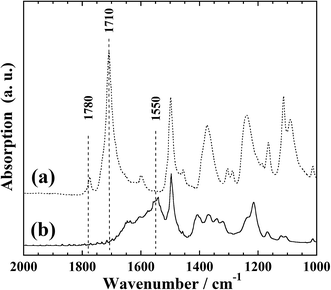
Fig. 1 presents the FTIR-ATR spectra of the polyimide films before and after KOH treatment. In Fig. 1(a), two absorption bands at 1780 and 1710 cm−1 can be observed; these correspond to the symmetric and asymmetric stretching vibrations, respectively, of the carbonyl groups of the imide ring of polyimide.22,25These two absorption bands are not present in Fig. 1(b). However, an absorption band at 1550 cm−1 and a broad absorption band at 1500–1700 cm−1 can be observed; the former corresponds to the N–H bending vibration of the amide bonds formed by hydrolysis of the imide ring, while the latter is considered to originate from the stretching vibration of carboxyl groups complexed with potassium ions. This is in good agreement with a previous report,25 indicating the formation of cation-exchange groups on the film surface upon KOH treatment.
Formation of NiNP-containing polyimide films
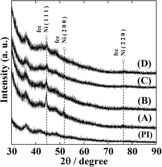
Fig. S1† shows the XRD patterns of NiNP-containing polyimide (Ni-NPs/PI) films prior to annealing. No clear diffraction peaks corresponding to face-centred cubic (fcc) Ni metal were observed, demonstrating the amorphous nature of the Ni-NPs/PI films. After annealing the Ni-NPs/PI films at 300 °C for 2 h under a nitrogen atmosphere, the XRD patterns contained two peaks corresponding to fcc Ni metal at 2θ = 44.5°and 51.8°, confirming the presence of crystalline nickel metal (Fig. 2). Sample (A) is a film with metallic lustre and shows conductivity; therefore, Ni metal is considered to get deposited in a film form.The nickel ions formed metallic clusters that afforded a weak peak on the high-angle side of the XRD patterns.
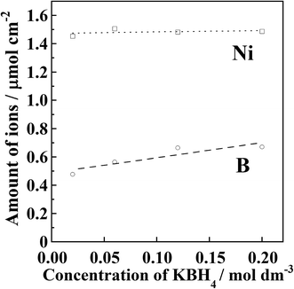
Fig. 3 shows the results of quantitative analysis of nickel and boron ions in the samples after the Ni2+ reduction treatment. It was found that the amount of deposited Ni did not change although the reducing agent concentration was different. The average Ni content in the precursor films after the introduction of Ni2+ ions was 1.48 μmol cm−2. Residual Ni2+ ions inside the resin were removed by immersing the film in aqueous CH3COOH solution. In other words, if unreduced Ni2+ ions were present, the amount of deposited Ni should be lower than the initially introduced amount. Therefore, it is considered that all of the introduced Ni2+ ions were deposited as metallic nickel inside the polyimide resin.
The boron content in the samples was found to increase with increasing reducing agent concentration. Assuming that all of the boron atoms were mixed with the deposited nickel atoms, 6–8 wt% of boron should be contained in the deposited nickel. It has been reported that metallic nickel films produced by electroless plating are amorphous when the boron content exceeds approximately 3 wt%.26–30 It has also been reported that Ni nanoparticles become amorphous when phosphorus31–33 or boron34–38 is contained in the nanoparticles. Furthermore, when boron-containing nickel films are heated at 300–400 °C, nickel borides are formed. As shown in Fig. 2, no diffraction patterns corresponding to nickel borides were observed for the samples annealed at 300 °C. Therefore, it is considered that the detected boron content originated not from the deposited nickel but from reducing agent residue inside the modified layer.
Fig. 4 shows the cross-sectional TEM images, electron diffraction patterns, and Ni particle size distributions of the Ni-NPs/PI films prior to annealing. The electron diffraction patterns show halo patterns. This is the same tendency as the result shown by the XRD patterns in Fig. S1.† The nanoparticles are amorphous. The particle size distributions were obtained by counting the particles in the area (600 × 450 nm2) shown in Fig. 4. The mean diameters of the nanoparticles in the samples reduced with 0.06, 0.12, and 0.20 mol dm−3 KBH4 solutions were 19 ± 5, 14 ± 3, and 13 ± 4 nm, respectively. Therefore, the average particle size decreased with increasing KBH4 concentration. This is because nucleation predominates over nucleus growth and the rate of nucleation would be expected to increase with increasing KBH4 concentration. In general, particle deposition begins with a nucleus that initially acts as a seed for the growing particle before increasing in size. However, at low KBH4 concentrations, the BH4− ion does not diffuse deeply into the resin. Therefore, particle nucleation preferentially occurs near the resin surface where the reducing agent can penetrate. It is considered that this nucleus acts as a reduction centre to which Ni2+ ions diffuse, resulting in the growth of Ni particles. As the KBH4 concentration increases, the reducing agent can penetrate deeper into the reformed layer, such that the nucleus precipitates inside the reformed resin layer.
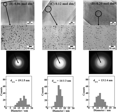 | ||
| Fig. 4 Cross-sectional TEM images and electron diffraction patterns of the Ni-NPs/PI films (B)–(D) shown in Fig. S1.† Particle size distributions of Ni nanoparticles are also shown. | ||
In addition, when the nucleation rate is higher, nucleation prevails over nanoparticle growth. Although the amount of Ni ions initially introduced was the same, the Ni was preferentially consumed for nucleation, and thus nanoparticle growth was suppressed. Therefore, the particle size decreased with increasing reducing agent concentration.
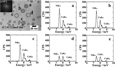
Fig. 5 shows the cross-sectional TEM images and EDS elemental analysis results for the Ni-NPs/PI films prior to annealing. The EDS elemental analysis of Ni was performed during TEM observation using a 15 nm electron beam and the same measurement time (25 s). The EDS spectra revealed a higher Ni abundance for the nanoparticles compared with the area lacking nanoparticles. No lattice images of nanoparticles were observed in high-resolution TEM images. An FFT image of the particle a supports this result. Therefore, based on the XRD, EDS, and high-resolution TEM results, the formed nanoparticles are considered to be composed of amorphous Ni metal. Moreover, small amounts of Ni were detected in the area of the resin surrounding the particles, possibly indicating Ni clusters that could not be observed by TEM.
Nanoparticles with an average size of 3–12 nm were observed in the samples reduced at temperatures of 30, 40, and 50 °C. Fig. S2† shows cross-sectional TEM image and particle size distributions of a Ni-NPs/PI film reduced at 50 °C. The electron diffraction and EDS results revealed that the formed NiNPs consisted of metallic nickel with an fcc structure. The average particle size of the nanoparticles in the sample reduced at 30 °C was 11 nm, and smaller particles with a size of approximately 4 nm were also formed in the samples reduced at 40 and 50 °C. The number of these smaller particles increased with increasing reduction temperature, and the number of particles around 10 nm also increased and their sizes tended to decrease. Therefore, a low reduction temperature promoted nucleus growth, resulting in increased particle size. Conversely, a high temperature increased the rate of the reduction reaction and led to faster nucleation, thereby increasing nucleation progresses relative to nucleus growth and leading to an increased number of particles and decreased particle size.
Effect of repeated adsorption/reduction treatment
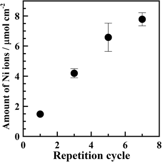
Fig. S3† shows XRD patterns of samples subjected to repeated adsorption/reduction of Ni2+ ions. No diffraction patterns attributable to metallic nickel were observed, indicating that the deposited nickel was in an amorphous or quite fine crystallite state.Fig. 6 shows that the Ni content increased with an increasing number of adsorption/reduction cycles, confirming the feasibility of increasing the amount of Ni in the polyimide resin by repeated adsorption/reduction treatment.
Fig. S4† shows cross-sectional TEM images of the samples subjected to repeated adsorption/reduction of Ni2+ ions. The formation of nanoparticles with an average particle size of 10–30 nm was confirmed in all of the samples. The surfaces of the resins subjected to three, five, and seven adsorption/reduction cycles were not covered with films, but were instead occupied by a large amount of deposited nanoparticles. In addition, the particles were dispersed throughout the reformed layer, and tended to be deposited in the deepest part of the reformed layer. Furthermore, comparison of the samples subjected to three, five, and seven adsorption/reduction cycles revealed that large particles were dispersed throughout the entire reformed layer in the sample subjected to seven cycles.
As shown by the particle size distributions in Fig. S4,† the average particle size was approximately 28 nm for the three samples. To obtain these distributions, all of the particles in the entire region (1.6 × 1.2 μm2) of the TEM images were counted. This average particle size of 28 nm is more than double that observed for the sample subjected to a single adsorption/reduction cycle. Furthermore, increasing the number of cycles from three to seven had little effect on the number of particles with a size of 30 nm or more and no change in the total number of particles was observed. This finding seems to contradict the results shown in Fig. 6, where the Ni content was found to increase with an increasing number of cycles. This suggests that an increased number of cycles resulted in an increased number of particles with diameters smaller than those shown in Fig. S4.†
Fig. 7 shows high-resolution cross-sectional TEM images and the number of particles per unit area for the samples subjected to repeated adsorption/reduction of Ni2+ ions; the arrows in Fig. 7(a)–(c) indicate the presence of numerous particles with sizes of several nanometers or less. However, since these particles are small in size and located inside the resin, the contrast of the particle image is not clear. Since it was difficult to precisely specify the particle size, the number of identified particles was counted in the whole region (250 × 150 nm2) shown in the enlarged view. The number of particles per unit area is shown in Fig. 7(b). The results revealed that the number of particles increased with an increasing number of cycles. This is consistent with the tendency shown in Fig. 6 for the amount of Ni. It is presumed that the rigid polymer network inhibited the growth of particles with sizes of 30 nm or greater; therefore, the number of large particles remained approximately constant while the number of small particles increased.
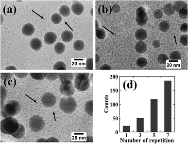 | ||
| Fig. 7 High resolution cross sectional TEM images of the samples prepared by repeated Ni2+ ion adsorption/reduction treatments with for (a) three, (b) five, and (c) seven cycles. The counts in (d) were obtained for each area of 250 × 150 nm2 in (a)–(c). The counts for one repetition number in (d) were obtained from the particle size distribution for an area of 250 × 150 nm2 in the area d in Fig. 5. | ||
Fig. S5† presents electron diffraction patterns of the samples. The sample subjected to three adsorption/reduction cycles exhibited a halo pattern, whereas the samples subjected to five or seven cycles afforded spot-like diffraction images similar to the image observed for the polycrystalline phase. However, it was difficult to interpret the diffraction images owing to the large number of spots present. Based on the ICDD data, the XRD patterns of Ni with the fcc structure, NiB, Ni2B, and Ni3B were compared, as shown in Fig. S6.† Numerous peaks corresponding to nickel borides were observed on both the low- and high-diffraction-angle sides of the Ni(111) and Ni(200) peaks. As shown in Fig. S5(c) and (d),† diffraction spots were also observed at positions closer to the Ni(111) and Ni(200) planes of fcc Ni. The above results indicate that nickel boride nanoparticles were present in parts of the deposited material. The formation of nickel borides with high crystallinity is probably attributable to the facile incorporation of boron atoms into the precipitates upon prolonged exposure to high concentrations of KBH4.
Conclusions
Liquid-phase reduction of Ni2+ ions in polyimide films was found to result in the precipitation of Ni in the form of a film on the surface of the resin or nanoparticles inside the resin, depending on the reducing agent concentration. At low reducing agent concentrations, NiNPs with an average particle size of 10–20 nm were formed inside the resin. As the reducing agent concentration was increased, the particles became more deeply dispersed in the modified layer and the average particle size tended to decrease. From the results of no lattice fringes observed in the high-resolution TEM images, electron diffraction patterns, and EDS analysis, it is highly probable that the formed NiNPs were amorphous metallic Ni. Nickel was also detected in the resin surrounding the particles, which was ascribed to the presence of Ni clusters not visible by TEM. Regarding particle precipitation, as the reducing agent concentration was increased, the precipitated particles displayed a tendency to spread inside the modified resin layer, and a tendency toward a smaller average particle size was also observed.Nanoparticles with an average size of 3–12 nm were formed in the samples reduced at temperatures of 30, 40, or 50 °C. The number of these small particles increased with increasing temperature, and the number of particles around 10 nm also increased and their sizes tended to decrease. Higher temperatures led to an increased nucleation rate and favoured nucleation rather than nucleus growth, resulting in an increased number of particles and decreased particle size.
Samples subjected to three, five, or seven adsorption/reduction cycles were found to possess an average particle size of approximately 28 nm. The surfaces of the resins subjected to these adsorption/reduction cycles were not covered with films, but were instead occupied by a large amount of deposited nanoparticles. The number of particles increased with an increasing number of cycles. This is consistent with the tendency observed for the Ni content with an increasing number of cycles. It is considered that the rigid polymer network inhibited the growth of particles with sizes of 30 nm or greater, causing the number of large particles to remain approximately constant while the number of smaller particles increased. It was therefore possible to increase both the number of particles and Ni content by performing repeated adsorption/reduction cycles. Electron diffraction results and ICDD data indicated that nickel boride nanoparticles with high crystallinity were present in parts of the deposited material. The formation of these nickel borides is probably attributable to the facile incorporation of boron atoms into the precipitates upon prolonged exposure to high concentrations of KBH4.
Conflicts of interest
There are no conflicts to declare.Acknowledgements
The authors thank the late Dr Masao Matsuoka for his eager direction and encouragement.Notes and references
- C. L. Tsai, H. J. Yen and G. S. Liou, React. Funct. Polym., 2016, 108, 2–30 CrossRef CAS.
- F.-Y. Shen, S.-E. Huang and W.-P. Dow, ECS Electrochem. Lett., 2013, 2, 45–48 CrossRef.
- T. W. Kim, J. H. Jung, C. S. Yoon and Y. H. Kim, Appl. Phys. Lett., 2008, 92, 042103 CrossRef.
- R. Singh and S. Prakash, Surf. Sci., 2003, 532–535, 272–275 CrossRef CAS.
- D. Salz, B. Mahltig, A. Baalmann, M. Wark and N. Jaeger, Phys. Chem. Chem. Phys., 2000, 2, 3105–3110 RSC.
- C. W. Hsu, B. Zhen, W. Qiu, O. Shapira, B. G. DeLacy, J. D. Joannopoulos and M. Soljačić, Nat. Commun., 2014, 5, 1–6 Search PubMed.
- H. Choi, S.-J. Ko, Y. Choi, P. Joo, T. Kim, B. R. Lee, J.-W. Jung, H. J. Choi, M. Cha, J.-R. Jeong, I.-W. Hwang, M. H. Song, B.-S. Kim and J. Y. Kim, Nat. Photonics, 2013, 7, 732–738 CrossRef CAS.
- I. Toda, T. Tsuruoka, J. Matsui, T. Murashima, H. Nawafune and K. Akamatsu, RSC Adv., 2014, 4, 4723–4726 RSC.
- S. Tomita, P. E. Jönsson, K. Akamatsu, H. Nawafune and H. Takayama, Phys. Rev. B, 2007, 76, 174432 CrossRef.
- J. H. Kim and C. S. Yoon, Thin Solid Films, 2008, 516, 4845–4850 CrossRef CAS.
- S. Hasebe, S. Aoyama, M. Tanaka and H. Kawakami, J. Membr. Sci., 2017, 536, 148–155 CrossRef CAS.
- E. P. Favvas, F. K. Katsaros, S. K. Papageorgiou, A. A. Sapalidis and A. C. Mitropoulos, React. Funct. Polym., 2017, 120, 104–130 CrossRef CAS.
- Y. J. Cheng, S. Renker, Z. Sun and J. S. Gutmann, Macromol. Rapid Commun., 2005, 26, 613–619 CrossRef CAS.
- Y. Dirix, C. Bastiaansen, W. Caseri and P. Smith, J. Mater. Sci., 1999, 34, 3859–3866 CrossRef CAS.
- V. Zaporojtchenko, J. Zekonyte, A. Biswas and F. Faupel, Surf. Sci., 2003, 532–535, 300–305 CrossRef CAS.
- S. Clémenson, D. Léonard, D. Sage, L. David and E. Espuche, J. Polym. Sci., Part A: Polym. Chem., 2008, 46, 2062–2071 CrossRef.
- T. Del Castillo-Castro, E. Larios-Rodriguez, Z. Molina-Arenas, M. M. Castillo-Ortega and J. Tanori, Composites, Part A, 2007, 38, 107–113 CrossRef.
- T. C. Wang, M. F. Rubner and R. E. Cohen, Langmuir, 2002, 18, 3370–3375 CrossRef CAS.
- S. Ikeda, K. Akamatsu, H. Nawafune, T. Nishino and S. Deki, J. Phys. Chem. B, 2004, 108, 15599–15607 CrossRef CAS.
- K. Akamatsu, S. Adachi, T. Tsuruoka, S. Ikeda, S. Tomita and H. Nawafune, Chem. Mater., 2008, 20, 3042–3047 CrossRef CAS.
- K. Akamatsu, S. Ikeda and H. Nawafune, Langmuir, 2003, 19, 10366–10371 CrossRef CAS.
- Y.-S. Hsiao, W.-T. Whang, S.-C. Wu and K.-R. Chuang, Thin Solid Films, 2008, 516, 4258–4266 CrossRef CAS.
- K. Akamatsu, K. Nakahashi, S. Ikeda and H. Nawafune, Eur. Phys. J. D, 2003, 24, 377–380 CrossRef CAS.
- K. Akamatsu, S. Ikeda, H. Nawafune and S. Deki, Chem. Mater., 2003, 15, 2488–2491 CrossRef CAS.
- R. R. Thomas, S. L. Buchwalter, L. P. Buchwalter and T. H. Chao, Macromolecules, 1992, 25, 4559–4568 CrossRef CAS.
- P. S. Kumar and P. K. Nair, Nanostruct. Mater., 1994, 4, 183–198 CrossRef CAS.
- V. Vitry and L. Bonin, Surf. Coat. Technol., 2017, 311, 164–171 CrossRef CAS.
- V. Vitry, A. F. Kanta, J. Dille and F. Delaunois, Surf. Coat. Technol., 2012, 206, 3444–3449 CrossRef CAS.
- K. Krishnaveni, T. S. N. Sankara Narayanan and S. K. Seshadri, Surf. Coat. Technol., 2005, 190, 115–121 CrossRef CAS.
- A. F. Kanta, V. Vitry and F. Delaunois, Mater. Lett., 2009, 63, 2662–2665 CrossRef CAS.
- K. Mandel, F. Dillon, A. A. Koos, Z. Aslam, K. Jurkschat, F. Cullen, A. Crossley, H. Bishop, K. Moh, C. Cavelius, E. Arzt and N. Grobert, Chem. Commun., 2011, 47, 4108–4110 RSC.
- J. Wang, A. C. Johnston-Peck and J. B. Tracy, Chem. Mater., 2009, 21, 4462–4467 CrossRef CAS.
- S. Xie, M. Qiao, W. Zhou, G. Luo, H. He, K. Fan, T. Zhao and W. Yuan, J. Phys. Chem. B, 2005, 109, 24361–24368 CrossRef CAS PubMed.
- J. Guo, Y. Hou, B. Li and E. Duan, Mater. Lett., 2017, 200, 90–93 CrossRef CAS.
- J. Shao, X. Xiao, X. Fan, L. Chen, H. Zhu, S. Yu, Z. Gong, S. Li, H. Ge and Q. Wang, Mater. Lett., 2013, 109, 203–206 CrossRef CAS.
- Z. Wu, M. Zhang, Z. Zhao, W. Li and K. Tao, J. Catal., 2008, 256, 323–330 CrossRef CAS.
- F. Wu, Z. Zhang, F. Zhang, D. Duan, Y. Li, G. Wei, S. Liu, Q. Yuan, E. Wang and X. Hao, Electrochim. Acta, 2018, 287, 115–123 CrossRef CAS.
- Z. L. Schaefer, X. Ke, P. Schiffer and R. E. Schaak, J. Phys. Chem. C, 2008, 112, 19846–19851 CrossRef CAS.
Footnote |
| † Electronic supplementary information (ESI) available. See DOI: 10.1039/c9ra00182d |
| This journal is © The Royal Society of Chemistry 2019 |

