 Open Access Article
Multi-shelled ZnO decorated with nitrogen and phosphorus co-doped carbon quantum dots: synthesis and enhanced photodegradation activity of methylene blue in aqueous solutions
Shaojia Songabc,
Kun Wuabcd,
Huadong Wuabc,
Jia Guoabc and
Linfeng Zhang *abce
*abce
aKey Laboratory for Green Chemical Process of Ministry of Education, Wuhan Institute of Technology, Wuhan, 430205, PR China. E-mail: lfzhang@wit.edu.cn
bKey Laboratory of Novel Reactor and Green Chemical Technology of Hubei Province, Wuhan Institute of Technology, Wuhan 430205, PR China
cSchool of Chemical Engineering and Pharmacy, Wuhan Institute of Technology, Wuhan 430205, PR China
dCollege of Post and Telecommunications, Wuhan Institute of Technology, Wuhan 430073, PR China
eSchool of Chemical Engineering and Technology, Tianjin University, Tianjin 300072, PR China
First published on 6th March 2019
Abstract
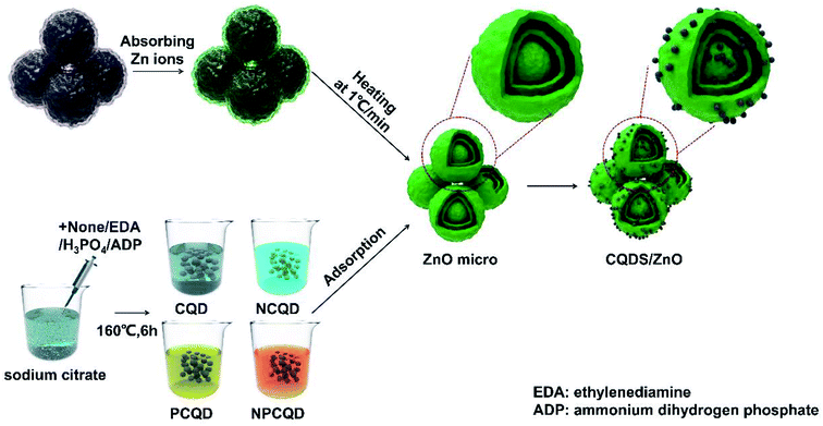
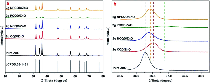
The presence of organic dyes in wastewater has posed a huge threat to aquatic life and human health. In this study, nitrogen and phosphorus co-doped carbon quantum dot (CQD)-decorated multi-shelled ZnO microsphere photocatalysts (NPCQD/ZnO) were obtained via a simple absorption process; ZnO was prepared by calcining carbon microspheres as the sacrificial template. The as-prepared NPCQD/ZnO showed an obvious multi-shelled structure with the nitrogen and phosphorus co-doped CQDs homogeneously attached onto the inner and outer shells of ZnO. According to the UV-Vis DRS results, all the co-doped, single-doped and undoped carbon quantum dots could enhance the efficiency of absorption of visible light and reduce the optical band gap. Furthermore, the PL characterization results showed that the NPCQD/ZnO composites had lowest fluorescence intensity because the decoration of ZnO with NPCQDs could effectively reduce the recombination rate of photogenerated electron–hole pairs in the ZnO semiconductor photocatalyst. Importantly, 2 g-NPCQD/ZnO composites exhibited higher photodegradation performance towards methylene blue (MB) than pure ZnO and even the newly reported series of ZnO catalysts under the same conditions. Moreover, the degradation obeyed the pseudo-first-order and Langmuir–Hinshelwood kinetics models with a reaction constant of 0.0725 min−1, which was 1.05 times that of pure ZnO (0.0353 min−1). The NPCQD/ZnO composites not only showed good photocatalytic performance, but also had excellent stability since the photocatalytic activity did not significantly decrease after five cycling tests. In addition, compared with single-doped and undoped carbon quantum dots, N and P co-doped carbon quantum dots have more significant efficiency for the modification of semiconductor photocatalysts. The present study shows that the CQD-decorated multi-shelled ZnO can be regarded as an excellent photocatalyst candidate in the field of water treatment. Moreover, this new concept is helpful in the controllable construction of other multi-shelled metal oxides decorated with co-doped carbon quantum dots with enhanced photocatalytic properties.
1 Introduction
In addition to water shortage, water pollution caused by the discharge of organic and toxic pollutants is becoming a challenge for the sustainable development of the world economy and society.1–5 In recent years, the photocatalytic route has proven to be a completely green technique that avoids the use of any auxiliary material in the one-step thorough elimination of pollutants under UV-light irradiation.6–9 It has been reported that various semiconductor metal oxides, such as TiO2, ZnO, Bi2O3, BiOBr, AgBr, etc., can serve as ideal photocatalysts due to their properties of low toxicity, high catalytic efficiency and significant stability.10–17 Among these, zinc oxide (ZnO), as an important n-type semiconductor photocatalyst, has been widely used in wastewater treatment, environmental purification, and bacteriostatic/photocatalytic sterilization because of its advantages of non-toxicity, high electron exchange performance, low cost and easy accessibility.18–23 Under the excitation of UV-Vis light, nano-ZnO can degrade toxic pollutants and transform them into small inorganic molecules. A number of toxic organic pollutants, such as 2,4,6-trichlorophenol,24 phenol,25 and methyl parathion,26 and inorganic pollutants27 can be effectively removed by this method. However, there are several challenges in using nano-ZnO as a photocatalyst: first, the band gap (Eg = 3.2 eV) of ZnO signifies that ZnO can only respond to ultraviolet light of less than 380 nm wavelength (3–5% of sunlight); second, the photoinduced electrons and hole pairs of ZnO can easily recombine, and therefore, its effective charge efficiency is low;28,29 and third, the photocorrosion of ZnO is serious, and ZnO is not resistant to acids and strong alkalis. Therefore, how to improve the visible-light response, reduce the recombination rate of photoinduced electron–hole pairs and improve the stability are the directions for the modification and applications of ZnO photocatalyst.Compared with other nanostructured materials, semiconductor materials with core–shell or even hollow structures have drawn significant attention because of their obvious advantages such as low density and large specific surface area.30,31 Among them, a multi-shelled structure is considered to be a special core–shell structure, which has superior performance when compared with a simple single-layer structure. Wang et al.32 obtained multi-shelled ZnO hollow spheres by exercising accurate control and found that the prepared samples exhibited higher energy conversion efficiency than the single-shelled ZnO hollow spheres. This excellent performance might be attributed to the novel structure that had larger surface areas and the ability to reflect and scatter light. Zeng et al.33 prepared hollow ZnO microspheres with different thicknesses of shells using carbon spheres as a template. The UV-Vis DRS tests showed that ZnO with a multi-shelled structure had better light response than its single-shelled and nanoparticle counterparts. In addition to the experimental results, the theoretical calculations indicated that ZnO with a multi-shelled structure had a smaller band gap than that with bare spheres.34 Moreover, the degradation experiments showed that ZnO with this novel structure exhibited better photocatalytic activity towards methyl orange.
Carbon quantum dots (CQDs), as a newly found quasi-zero-dimensional nanomaterial, have attracted extensive attention due to their wide absorption band, high optical absorption coefficient and chemical stability. Moreover, the unique up-conversion luminescence of CQDs can be excited by light with higher wavelengths and lower frequencies, and then, the CQDs emit low-wavelength light with higher frequency. In addition, the CQDs can be used as electron acceptors to partly reduce the recombination rate of photogenerated electron–hole pairs and then enhance the photocatalytic activity when combined with a photocatalytic semiconductor.35 In this regard, the CQDs could play an important role in the design of composite semiconductor photocatalysts. Zhang et al.36 synthesized CQD/ZnO nanoflower composites by a two-step method and found that the prepared composite exhibited excellent visible-light catalytic activity towards the degradation of rhodamine B. Ding et al.37 synthesized carbon quantum dots (CQDs) attached on the surface of ZnO with irregular, hierarchical pores. The CQD/ZnO composites reported in the literature have been synthesized by a facile process in which the ZnO foam is dispersed in a CQD solution. The results showed that these composites had good visible-light catalytic performance when compared with the pure ZnO photocatalysts.
In recent years, researchers have made good progress in the development of synthesis methods, optical properties and application prospects of CQDs. In addition to the CQDs combined with other nanomaterials, CQDs doped with some nonmetallic elements (such as N, P, S, Cl, etc.) can exhibit more stable optical properties, higher quantum yields and extremely excellent catalytic performances, as indicated by numerous previously reported studies.35,38 Hu et al.39 synthesized N-doped CQDs, Cl-doped CQDs and undoped CQDs by a hydrothermal method. The fluorescence intensity sequences of the prepared samples were as follows: N-doped CQDs > undoped CQDs > Cl-doped CQDs, indicating that the Cl radicals might decrease the recombination of the photogenerated electron–hole pairs. Huang et al.40 prepared NCQD/TiO2 and CQD/TiO2 composites. The UV-Vis diffuse reflection absorption spectra showed that the NCQD/TiO2 composite had better photocatalytic performances due to the stronger light absorption intensity and narrower optical band gaps when compared with the CQD/TiO2 composites.
However, to the best of our knowledge, studies reported on the photocatalysts of CQD/ZnO composite materials mainly focus on the structure with single-shelled hollow microspheres. Furthermore, the composited CQDs are usually undoped or single element-doped. In addition, there are a few studies on the preparation and investigation of multielement co-doped CQDs decorated-composited on multi-shelled ZnO composite materials as an effective photocatalyst. Therefore, multi-shelled ZnO materials, N and P single-doped and co-doped CQDs, and a series of CQD/ZnO composites were facilely obtained in this study. The photocatalytic performances of the composites were studied through the degradation of simulated wastewater with methylene blue dye under daylight. The morphology, structure, and optical properties of the prepared composites have been analyzed, and the possible mechanism for the enhanced photocatalytic performance has been discussed.
2 Experimental
2.1 Synthesis
Zinc nitrate hexahydrate (Zn(NO3)2·6H2O), sucrose, sodium citrate dihydrate, ammonium dihydrogen phosphate (ADP), phosphoric acid, ethylenediamine (EDA) and ethanol were purchased from the National Pharmaceutical Group Chemical Reagent Co., Ltd. All the chemicals were of reagent grade and used as raw materials without further purification.The carbon microsphere templates were synthesized through the emulsion polymerization reaction of sugar under hydrothermal conditions.41 The typical synthesis process has been described as follows: 130 g sucrose is dissolved in 250 mL deionized water under magnetic stirring for 30 min at room temperature to form a homogeneous transparent solution (concentration: about 1.5 mol L−1). After this, the mixture is transferred to a 500 mL Teflon-lined stainless steel autoclave and maintained at 200 °C for 125 min; then, the autoclave is cooled down to room temperature. The products are alternately washed several times with deionized water and absolute ethanol. Finally, the filter cake is dried at 60 °C for 12 h to obtain the carbon microsphere templates.
The preparation of the multi-shelled ZnO spheres was conducted using the method described by Wang et al.32 At first, 45 g zinc nitrate hexahydrate was dissolved in a 30 mL mixed solution composed of 10 mL absolute ethanol and 20 mL deionized water. The mixture was stirred to form a homogeneous solution. Then, 1 g of carbon microsphere templates was evenly dispersed in the abovementioned solution followed by ultrasonication for 15 min. The resulting suspension was stirred at 40 °C for 12 h. After this, it was filtered and washed with deionized water. After being dried at 80 °C for 12 h, the products were heated to 400 °C at the rate of 1° min−1, calcined at 400 °C for 30 min, then heated to 500 °C at the rate of 1° min−1 and maintained at this temperature for 60 min in the muffle furnace to remove the carbon templates. After the furnace was naturally cooled down to room temperature, the resulting product was obtained.
The detailed synthesis process has been described herein. For the typical synthesis process, 11.7 g sodium citrate and 0.5 g ammonium dihydrogen phosphate (mole ratio is about 10![[thin space (1/6-em)]](https://www.rsc.org/images/entities/char_2009.gif) :
:![[thin space (1/6-em)]](https://www.rsc.org/images/entities/char_2009.gif) 1) were dissolved in 40 mL deionized water. The mixture was constantly stirred for 15 min at room temperature to form a clear and transparent solution. After this, the mixture was transferred to a 100 mL Teflon-lined stainless steel autoclave and maintained at 160 °C for 6 h; then, the autoclave was cooled down to room temperature. The product was filtered by a 0.25 μm membrane to remove the impurities and large particles. In addition, the filtrate was further purified by a dialysis membrane (MWCO = 1000 Da) for 24 h to obtain the final NPCQD solution. The final solution was placed in a refrigerator at 4 °C for further use.
1) were dissolved in 40 mL deionized water. The mixture was constantly stirred for 15 min at room temperature to form a clear and transparent solution. After this, the mixture was transferred to a 100 mL Teflon-lined stainless steel autoclave and maintained at 160 °C for 6 h; then, the autoclave was cooled down to room temperature. The product was filtered by a 0.25 μm membrane to remove the impurities and large particles. In addition, the filtrate was further purified by a dialysis membrane (MWCO = 1000 Da) for 24 h to obtain the final NPCQD solution. The final solution was placed in a refrigerator at 4 °C for further use.
For comparison, the phosphorus-doped, nitrogen-doped and undoped carbon quantum dots were prepared in this study via similar procedures using different phosphorus and nitrogen sources. For the preparation of the phosphorus-doped carbon quantum dots (PCQDs) and nitrogen-doped carbon quantum dots (NCQDs), ammonium dihydrogen phosphate was replaced with phosphoric acid and ethylenediamine, respectively. The undoped carbon quantum dots (CQDs) were prepared using only sodium citrate without the addition of ammonium dihydrogen phosphate.
2.2 Characterization
The crystal structures of the as-prepared CQD-decorated multi-shelled ZnO composites were analyzed by X-ray diffraction (XRD D8 ADVANCE and DAVINCI DESIGN) with Cu-Kα (λ = 1.5418 Å) radiation in the 2θ range of 20–80°. The BET surface area, pore volume, and pore size were characterized by nitrogen adsorption at liquid nitrogen temperatures using the Autosorb-iQ instrument (Quantachrome Instruments). The general morphology of the synthesized composites was analyzed by scanning electron microscopy (SEM) using Merlin compact-61-78 at the accelerating voltage of 10 kV. Transmission electron microscopy (TEM), high-resolution transmission electron microscopy (HRTEM), scanning transmission electron microscopy (STEM) and elemental mapping images were obtained using the Merlin compact-61-78 instrument to further investigate the structure and chemical compositions of the products.The UV-Vis absorption studies of the composites were conducted using a UV-Vis diffuse reflectance spectrophotometer (U-3900 spectrophotometer). The room-temperature photoluminescence (PL) spectrum was obtained using the F-4600 FL spectrophotometer (5j24000 01 model) at the excitation wavelength of 325 nm.
2.3 Testing of the photocatalytic activity
The photocatalytic activity of the catalysts was assessed by the degradation of methylene blue in a double-layer glass reactor. A 300 W xenon lamp (PLS-SXE300) was used to simulate the daylight source (full working current: 20 A; experimental current: 16 A). The typical evaluation process of the catalyst activity has been described as follows. Herein, 20 mg photocatalyst was dispersed in a 200 mL methylene blue solution (the concentration of MB was 10 mg L−1). Before conducting the photocatalytic reaction, the mixed solution was stirred for 30 min to achieve the adsorption–desorption equilibrium of the catalyst and MB. Subsequently, the photocatalytic reaction was performed. During the irradiation process, a small amount of dispersion was obtained at 0, 5, 15, 30, 45, and 60 min and centrifuged to remove the photocatalysts. Finally, the concentration of MB was measured using a UV-Vis spectrophotometer (PerkinElmer LAMBDA 35) to monitor the changes in the main absorbance centered at 665 nm.3 Results and discussion
3.1 Structure and morphology of the catalyst
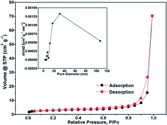
The N2 adsorption/desorption isotherm measurements were performed to investigate the specific surface areas and pore size distribution of the NPCQD/ZnO microspheres. The nitrogen adsorption isotherm is a typical IV-type curve with a distinct hysteresis loop in the range of ca. 0.4–1.0 P/P0 (Fig. 3), indicating the existence of mesoporous and macroporous structures.44 The BET surface area is measured to be 17.43 m2 g−1. In addition, according to the corresponding Barrett–Joyner–Halenda (BJH) pore size distribution curve (inset in Fig. 3), the pore size distribution of the NPCQD/ZnO microspheres is mainly between 5 and 50 nm, which can be mainly attributed to the mesoporous structure of the microsphere surfaces. In addition, the macropores mainly originated from the larger interstitial pores formed by the stacking of the hollow spheres.44,45
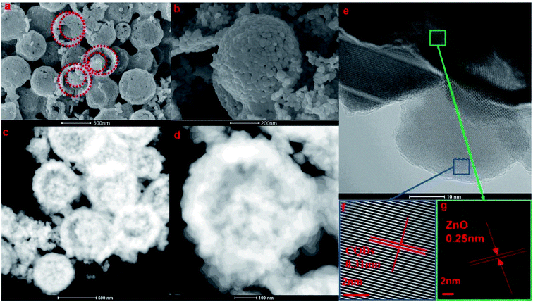 | ||
| Fig. 4 SEM images (a and b), scanning TEM images (c and d), and HRTEM images (e–g) of the prepared 2 g-NPCQD/ZnO composites. | ||
The components of the as-prepared 2 g-NPCQD/ZnO composites were further characterized by elemental mapping. Fig. 5b–f show the corresponding elemental distribution of the 2 g-NPCQD/ZnO nanospheres. The elemental mappings of the 2 g-NPCQD/ZnO composites show the presence of Zn, O, C, N and P, strongly confirming the existence of both phases of N and P-co-doped carbon quantum dots and multi-shelled ZnO; this is in agreement with the results of the HRTEM characterization. In addition, these elements are uniformly distributed inside and outside the surfaces of the ZnO double-shelled nanospheres. Based on the analysis of the TEM elemental mapping results, it can be concluded that ZnO and carbon quantum dots are nested within each other, and a complete spherical shell is formed rather than an isolated shell. Fig. 5g shows the mass content of the corresponding elements. The content of the N and P-co-doped carbon quantum dots in the composites is about 4%.
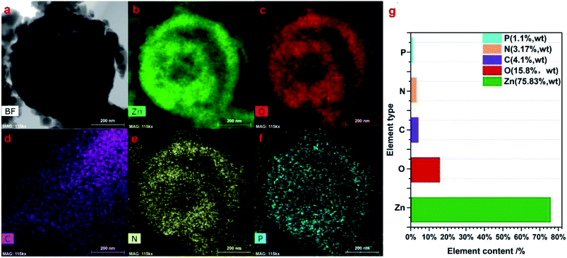 | ||
| Fig. 5 The corresponding elemental mapping images (a–f) and the elemental distribution of the prepared 2 g-NPCQD/ZnO composites (g). | ||
Moreover, carbon, nitrogen and phosphorus can be observed in the inner shell; this proves that the carbon quantum dots can be loaded onto the inner shell of ZnO. It can also be concluded from the TEM elemental mapping results that there are many interstitial pores between ZnO nanoparticles on the outer shell of the multi-shelled ZnO microspheres; thus, the loaded carbon quantum dots and organic pollutants involved in the photocatalytic reactions can enter the inner space through these holes on the outer shell. This finding is also consistent with the abovementioned SEM images.
3.2 Photocatalytic activity
The photocatalytic performances of the carbon quantum dot-decorated ZnO composites were evaluated for the degradation of MB (a common pollutant) in water under UV-Vis light irradiation.Currently, the widely recognized kinetic model for the photocatalytic degradation is the Langmuir–Hinshelwood (LH) model.46,47 The corresponding equation is as follows:
| r = −dc/dt = kKc/(1 + Kc) | (1) |
| r = −dc/dt = k | (2) |
In conclusion, the reaction rate is independent of C0. Linear fitting of the ln(C0/CT)–time curve yields a slope that is the reaction rate of the photocatalytic degradation.
Fig. 6 shows the plots of ln(C0/CT) versus irradiation time of the prepared photocatalysts. The ln(C0/CT) versus t presents a good linear relationship, which means that the photodegradation of MB on these photocatalysts obeys the rules of the LH kinetic model and the first-order reaction kinetics. In Fig. 6, it is evident that different element-doped carbon quantum dot-decorated ZnO composites have an appropriate decoration ratio. Interestingly, from the results, we can obviously determine that the best photocatalytic degradation rate for the CQD-decorated multi-shelled ZnO is at the same decoration ratio (the adsorbent CQD solution is 2 g). However, it is evident that the photocatalytic activity of 2.5 g-PCQD/ZnO is worse than that of pure ZnO (Fig. 6c). This indicates that the composite of multi-shelled ZnO and a suitable amount of carbon quantum dots can effectively improve the visible photocatalytic activity. Therefore, controlling an appropriate amount of the loaded carbon quantum dots is an important factor to improve the photocatalytic activity of the composites.
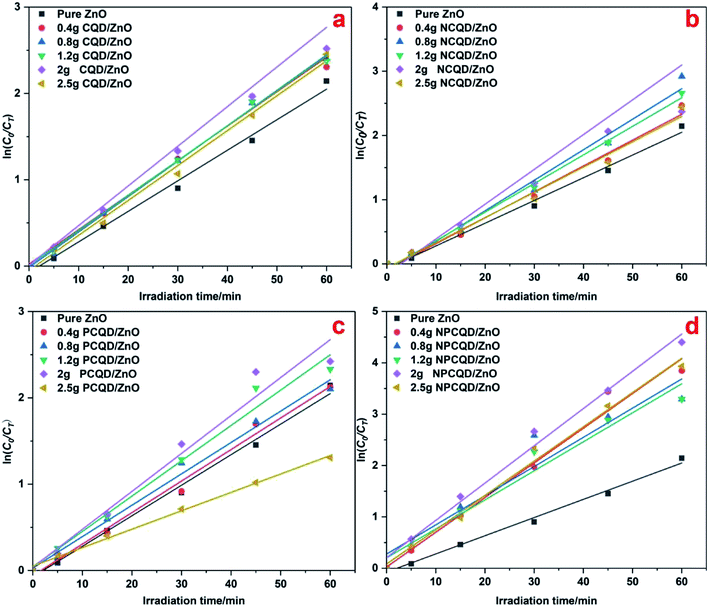 | ||
| Fig. 6 Photocatalytic degradation kinetic data of the CQD/ZnO composites under UV-Vis light: (a) CQD/ZnO; (b) NCQD/ZnO; (c) PCQD/ZnO; and (d) NPCQD/ZnO. | ||
Among all the composites of CQD-decorated multi-shelled ZnO, the obtained ZnO composites exhibit highest photocatalytic activity when the amount of the CQD solution is controlled at 2 g. The reason for this may be that the CQD/ZnO composite can improve the light utilization through its unique up-conversion characteristics;35 however, the photocatalytic activity of the carbon quantum dots is weaker than that of ZnO. Thus, the higher the content of the carbon quantum dots decorated on the ZnO shells, the more the competition between the light absorption capacities of ZnO and carbon quantum dots; this will lead to a decline in the photocatalytic activity;36 to study the photocatalytic activity of ZnO decorated with different kinds of carbon quantum dots, we have selected the same decoration ratio (the amount of CQDs in all the adsorption CQD solutions is controlled at 2 g) as a standard to formulate the CT/C0–time and ln(C0/CT)–time graphs, as shown in Fig. 7. It can be clearly seen from Fig. 7a that the photocatalytic activity of multi-shelled ZnO has been significantly improved after decoration with the carbon quantum dots. Among these, 2 g-NPCQD/ZnO shows highest photocatalytic activity with a degradation rate of up to 90% in only 30 min when compared with pure ZnO (degradation rate is 45% in 30 min). The photocatalytic degradation rate of the photocatalysts follows the order 2 g-NPCQD/ZnO > 2 g-PCQD/ZnO > 2 g-CQD/ZnO > 2 g-NCQD/ZnO > pure ZnO. Fig. 7b exhibits the linear fitting line of the curve of ln(C0/CT) versus time, where the slope represents the photocatalytic reaction rate constant.36 Table 1 lists the reaction kinetics equation and the corresponding parameters of the photocatalytic degradation of MB for the as-prepared photocatalysts. The apparent reaction rate constants (k) are 0.0353, 0.0424, 0.0417, 0.0439, and 0.0725 min−1 for pure ZnO, 2 g-CQD/ZnO, 2 g-NCQD/ZnO, 2 g-PCQD/ZnO, and 2 g-NPCQD/ZnO, respectively. Thus, the photocatalytic degradation rate of MB for 2 g-NPCQD/ZnO is 1.05 times that for pure ZnO. Furthermore, the k values of 2 g-PCQD/ZnO, 2 g-CQD/ZnO, 2 g-NCQD/ZnO are about 0.2–0.25 times that of pure ZnO.
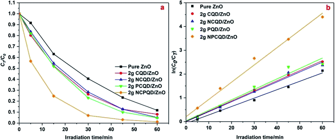 | ||
| Fig. 7 Photocatalytic degradation of MB with 2 g-CQD/ZnO composites: (a) plots of CT/C0 versus time and (b) plots of ln(C0/CT) versus time. | ||
| Catalyst | Fitting linear equation | Reaction rate constant (k/min−1) | Linear dependence (R2) |
|---|---|---|---|
| Pure ZnO | ln(C0/CT) = 0.0353t − 0.073 | 0.0353 | 0.99248 |
| 2 g-CQDs/ZnO | ln(C0/CT) = 0.0424t + 0.016 | 0.0424 | 0.99887 |
| 2 g-NCQDs/ZnO | ln(C0/CT) = 0.0417t + 0.001 | 0.0417 | 0.98911 |
| 2 g-PCQDs/ZnO | ln(C0/CT) = 0.0439t + 0.038 | 0.0439 | 0.9705 |
| 2 g-NPCQDs/ZnO | ln(C0/CT) = 0.07235t + 0.209 | 0.0725 | 0.98942 |
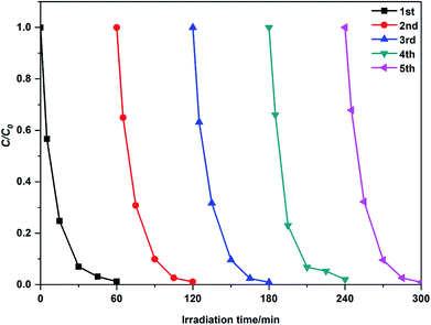
For comparison, Table 2 lists the kinetic data of the degradation of MB by the modified ZnO photocatalysts reported in the last two years. It can be concluded that 2 g-NPCQD/ZnO has a competitive photocatalytic degradation activity. Moreover, the stability of the NPCQD/ZnO composite for the degradation of MB was investigated for five cycles (as shown in Fig. 8). It can be seen that the photocatalytic activity is very stable. After the photocatalytic experiment is carried out for five times, the degradation rate efficiency slightly decreases only in the early stages of the photocatalytic reaction. Thus, the as-prepared NPCQD/ZnO composite has excellent chemical stability and can show effective industrial application prospects in the field of water treatment.
| Catalyst | Catalyst dosage | Degraded material | Reaction conditions | Reaction rate constant (k/min−1) | Reference |
|---|---|---|---|---|---|
| Sn-doped ZnO | 0.4 g L−1 | 0.2 g L−1 | 250 W Hg lamp | 0.054 | 48 |
| ZnO/graphene-oxide | — | 0.15 g L−1 | 125 W xenon lamp | 0.040 | 49 |
| N–ZnO/g-C3N4 | 1 g L−1 | 0.02 g L−1 | 300 W xenon lamp | 0.030 | 50 |
| Tartaric acid/ZnO | 0.8 g L−1 | 0.01 g L−1 | 300 W mercury lamp | 0.422 | 51 |
| AgBr/g-C3N4/ZnO | 0.4 g L−1 | 0.005 g L−1 | 300 W halogen lamp | 0.041 | 52 |
| ZnO/NiFe2O4 | 0.4 g L−1 | 0.2 g L−1 | 360 W UV-lamp | 0.029 | 53 |
| ZnO/CuO BTC | 1 g L−1 | — | Philips TL 15 W/5 BLB | 0.059 | 54 |
| Fe, Ni–ZnO | 1 g L−1 | 0.02 g L−1 | 300 W xenon lamp | 0.012 | 55 |
3.3 Mechanism of the photocatalytic activity enhancement
To reveal the functions of the decorated carbon quantum dots on the multi-shelled ZnO composites, the UV-Vis DRS and PL spectra of these photocatalysts were comprehensively studied. From the room-temperature UV-Vis DRS results shown in Fig. 9a, it can be observed that after decoration of the carbon quantum dots, the absorption edge of the multi-shelled ZnO composites shows a small red-shift, and the wavelength for the absorption edge increases. Although the absorption intensity of the carbon quantum dot-decorated multi-shelled ZnO composites almost remains the same as that of pure ZnO in the ultraviolet region, the absorbance of the composites in the visible light gradually increases with the decoration of different element-doped carbon quantum dots. In Fig. 9b, it is evident that the curves of 2 g-PCQD/ZnO and 2 g-CQD/ZnO have an intersection. The order of the intensity of absorption in the region larger than 440 nm changes as follows: 2 g-NPCQD/ZnO > 2 g-CQD/ZnO > 2 g-PCQD/ZnO > 2 g-NCQD/ZnO > pure ZnO. However, the intensity of absorption in the region less than 440 nm shows the sequence 2 g-NPCQD/ZnO > 2 g-PCQD/ZnO > 2 g-CQD/ZnO > 2 g-NCQD/ZnO > pure ZnO. Earlier studies have shown that ZnO mainly responds to ultraviolet light when used as a photocatalyst. Furthermore, the light source output in the photocatalytic performance is mainly concentrated in the region less than 440 nm. Hence, the order of absorption in the ultraviolet light region is well consistent with the photocatalytic performance.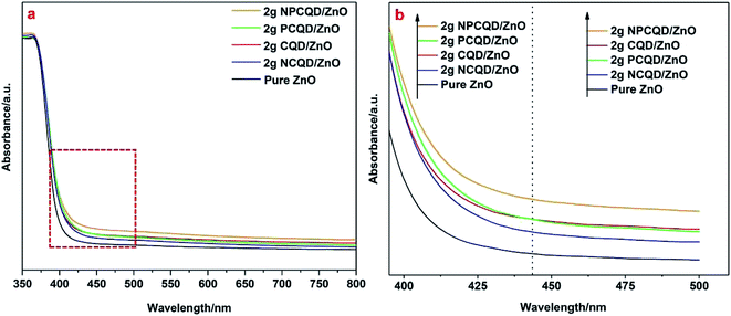 | ||
| Fig. 9 UV-Vis absorption spectra (a) and band edges of the as-synthesized multi-shelled ZnO composites decorated with different element -doped carbon quantum dots (b). | ||
Fig. 10 shows a plot of α(hv)0.5 vs. photon energy (hv) for the multi-shelled ZnO composites decorated with different element-doped carbon quantum dots. The direct band-gap energy (Ed) can be defined by the simplified formula α(hv) = C(hv − Ed)2.34 Herein, α is the absorption coefficient, hv is the photon energy with frequency v, and C is a constant. Hence, Ed can be calculated by the plot of α(hv)0.5 vs. photon energy (hv). The calculated direct band-gaps of 2 g-NPCQD/ZnO and 2 g-PCQD/ZnO exhibit the lowest value (3.13 eV), which is lower than those of 2 g-NCQD/ZnO and 2 g-CQD/ZnO (3.14 eV) and pure ZnO (3.165 eV).
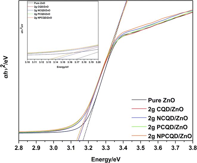 | ||
| Fig. 10 Tauc plot of the as-synthesized multi-shelled ZnO composites decorated with different element-doped carbon quantum dots. | ||
The narrower band gap and higher visible-light absorption lead to the participation of more photogenerated electron–hole pairs in the photocatalytic reaction. Thus, the composites of multi-shelled ZnO and doped carbon quantum dots exhibit promising applications as photocatalysts under visible light as compared to pure multi-shelled ZnO.
Normally, the photocatalytic performance of the catalysts may be influenced by several factors. It is significantly affected by the range of light response and the efficiency of light absorption. Moreover, the recombination of photogenerated electron holes is an important factor.
To confirm the photogenerated charge separation and recombination behaviors of the as-synthesized multi-shelled ZnO composites, the photoluminescence (PL) spectra of different composites were examined at 325 nm excitation (Fig. 11). Obviously, all the composites exhibit obvious PL signals with similar curve shapes; this suggests that the decoration of the CQDs does not generate a new PL signal. All the samples show strong visible emission spectra. In the background of this broad spectrum, one obvious emission peak could be observed, namely, the blue emission peak at the center of 475 nm. It is generally believed that blue ray emission resistance of the semiconductor ZnO is due to the surface oxygen vacancies and defects.56 The PL intensities of the single element-doped and undoped CQDs are stronger than that of pure ZnO; this indicates that the composite samples decorated with these carbon quantum dots have more surface defects.
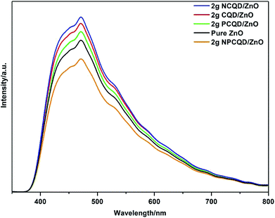 | ||
| Fig. 11 PL spectra of the as-synthesized multi-shelled ZnO composites decorated with different element-doped carbon quantum dots. | ||
It is clearly observed that the 2 g-NPCQD/ZnO composites show lowest emission intensity. Moreover, the sequence of the PL intensities for the single element-doped and undoped carbon quantum dots is as follows: 2 g-NCQD/ZnO < 2 g-CQD/ZnO < 2 g-PCQD/ZnO. The lower PL intensity indicates rapid charge transfer and lower recombination rate of the photogenerated electron–hole pairs, thus improving the photocatalytic activity.
Another confusing question worth considering is why the order of the PL intensity for the carbon quantum dot-decorated ZnO composites is 2 g-NPCQD/ZnO < 2 g-PCQD/ZnO < 2 g-CQD/ZnO < 2 g-NCQD/ZnO. As is well-known, many defects exist on the surface of the carbon quantum dots that can form visible band gaps, and these band gaps will constantly move from the interior towards the surface; this will result in energy band gap bending.57,58 The potential induced by the band gap bending affects the separation efficiency of the electrons and holes. The main cause of the surface band gap bending is the distribution and type of the surface groups. The NCQD/ZnO and PCQD/ZnO composites contain only nitrogen-containing and phosphorous-containing groups, respectively. All the composites of carbon quantum dots and ZnO have oxygen-containing groups.
Earlier studies have shown that oxygen-containing and nitrogen-containing groups induce upward band gap bending, and the same band gap bending direction slows down the separation of the electrons and holes.39 On the other hand, phosphorous-containing groups may induce a downward band gap bending, and this band gap bending direction is opposite to that in the case of the oxygen-containing or nitrogen-containing groups. Therefore, this band gap bending may be equivalent to the formation of a miniature electric field inside the composites, which may accelerate the separation of electrons from holes.39 The surface oxygen vacancies and defects of the ZnO composites can be increased by loading carbon quantum dots; therefore, these composites can exhibit better visible light response. In addition, due to the concurrence of oxygen-containing, nitrogen-containing and phosphorous-containing groups in the NPCQD/ZnO composites, bandgap bending induced by these three groups forms a miniature electric field in the photocatalysts, which promotes the transfer of photogenerated electron–hole pairs, and thus, the composites show lowest fluorescence intensity.
For the present enhancement analysis, the following mechanism was proposed under UV-Vis irradiation (Fig. 12). As shown in the previous literature,59 after CQDs are introduced into multi-shelled ZnO to form a composite system, a certain amount of visible light is converted into shorter-wavelength irradiation energy, which improves the light response range and absorption intensity. As a result, more photogenerated electron hole pairs are produced to participate in the photocatalytic reaction.
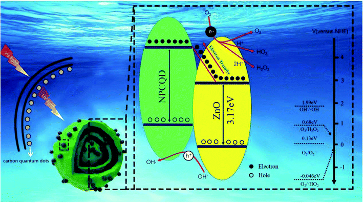 | ||
| Fig. 12 The proposed schematic diagram for the photocatalytic degradation of MB by the NPCQD/ZnO composites under UV-Vis irradiation. | ||
According to the previous studies, the LUMO level of the carbon quantum dots is in the range of 4.2–4.4 eV,40 and the conduction band (CB) of ZnO is 2.86 eV. Therefore, it is thermodynamically favorable to transfer electrons from the CB of ZnO to the VB of carbon quantum dots. Therefore, NPCQDs can promote the separation of photogenerated electron–hole pairs; this is in agreement with the PL results. On the other hand, when photocatalysts are irradiated, fewer photons enter the crystal structure. Some of these photons are directly absorbed, and the others are reflected. Due to the multi-shelled structure, more photons remain within the ZnO microsphere structure until completely absorbed; this is also considered as one of the reasons for the efficient photocatalysis. Based on the abovementioned advantages, the composites of N, P-co-doped carbon quantum dots and multi-shelled ZnO show efficient degradation rate for the MB solution and may be regarded as an excellent photocatalyst candidate in the field of water treatment.
4 Conclusion
In this study, a series of multi-shelled ZnO composites decorated with different element-doped/undoped carbon quantum dots were fabricated via a simple electrostatic adsorption approach. Among them, carbon quantum dots doped with different elements (mainly nitrogen and phosphorus) were synthesized by adjusting the reactant precursors under the same hydrothermal conditions. Multi-shelled ZnO was obtained by calcining the carbon microspheres as the sacrificial template. After characterization, the results showed that all the carbon quantum dots were attached onto the inner and outer shells of ZnO with uniform dispersion. The photocatalytic performances of these catalysts were evaluated for the degradation of MB under UV-Vis light irradiation. The pseudo-first-order reaction constant for the degradation of MB by the NPCQD/ZnO composite was two times that of pure ZnO. Moreover, the UV-Vis DRS spectrum indicates that NPCQD/ZnO has a wider light response range, higher light absorption intensity and smaller optical band gap than pure ZnO that result in more photogenerated electron–hole pairs. In addition, the PL spectrum revealed that the decoration of NPCQDs allowed better separation of the photogenerated electron–hole pairs on the ZnO surface. In addition, single-doped nitrogen and phosphorus CQDs together with undoped CQDs exhibited improvement in the light response range, light absorption intensity and optical band gap. In addition, compared with single-doped and undoped carbon quantum dots, N, P co-doped carbon quantum dots have more significant efficiency with respect to the modification of semiconductor photocatalysts. The present study shows that the prepared carbon quantum dot-decorated multi-shelled ZnO composites can be regarded as an excellent photocatalyst candidate in the field of water treatment. Furthermore, this new concept is helpful in the controllable construction of other multi-shelled metal oxides decorated with co-doped carbon quantum dots with enhanced properties for photocatalytic activity.Conflicts of interest
There are no conflicts to declare.Acknowledgements
This project was financially supported by the projects of China Postdoctoral Science Foundation funded project (2017M610491), the Key program of Natural Science Foundation of Hubei Province (No. 2016CFA079), and the Scientific Research Plan Project of Education Department of Hubei Province (No. B2017057).References
- Z. Wen, J. Ke, J. Xu, S. Guo, Y. Zhang and R. Chen, Chem. Eng. J., 2018, 343, 416–426 CrossRef CAS.
- S. Luo, F. Qin, Y. Ming, H. Zhao, Y. Liu and R. Chen, J. Hazard. Mater., 2017, 340, 253–262 CrossRef CAS PubMed.
- R. Wang, G. Cheng, Z. Dai, J. Ding, Y. Liu and R. Chen, Chem. Eng. J., 2017, 327, 371–386 CrossRef CAS.
- J. Ding, Z. Dai, F. Qin, H. Zhao, S. Zhao and R. Chen, Appl. Catal., B, 2017, 205, 281–291 CrossRef CAS.
- J. Ke, M. Adnan Younis, Y. Kong, H. Zhou, J. Liu, L. Lei and Y. Hou, Nano-Micro Lett., 2018, 10, 69 CrossRef PubMed.
- H. Tang, Z. Dai, X. Xie, Z. Wen and R. Chen, Chem. Eng. J., 2019, 356, 472–482 CrossRef CAS.
- H. Yang, X. Hu, C. Su, Y. Liu and R. Chen, Phys. Chem. Chem. Phys., 2017, 19, 31666–31674 RSC.
- J. Ke, X. Duan, S. Luo, H. Zhang, H. Sun, J. Liu, M. Tade and S. Wang, Chem. Eng. J., 2017, 313, 1447–1453 CrossRef CAS.
- F. Xu, G. Cheng, S. Song, Y. Wei and R. Chen, ACS Sustainable Chem. Eng., 2016, 4, 7013–7022 CrossRef CAS.
- Y. Gan, Y. Wei, J. Xiong and G. Cheng, Chem. Eng. J., 2018, 349, 1–16 CrossRef CAS.
- H. Long, L. Bao, A. A. Habeeb and P. Lu, Opt. Quantum Electron., 2017, 49, 1–8 CrossRef CAS.
- J. Ding, Z. Dai, F. Tian, B. Zhou, B. Zhao, H. Zhao, Z. Chen, Y. Liu and R. Chen, J. Mater. Chem. A, 2017, 5, 23453–23459 RSC.
- M. Yuan, F. Tian, G. Li, H. Zhao, Y. Liu and R. Chen, Ind. Eng. Chem. Res., 2017, 56, 5935–5943 CrossRef CAS.
- Z. Dai, F. Qin, H. Zhao, J. Ding, Y. Liu and R. Chen, ACS Catal., 2016, 6, 3180–3192 CrossRef CAS.
- Y. Tu, Q. Fu, X. Niu, J. Sang, Z. Tan and X. Zou, J. Mater. Sci. Technol., 2013, 29, 1053–1058 CrossRef CAS.
- Z. Dai, F. Qin, H. Zhao, F. Tian, Y. Liu and R. Chen, Nanoscale, 2015, 7, 11991–11999 RSC.
- H. Liu, M. Luo, J. Hu, T. Zhou, R. Chen and J. Li, Appl. Catal., B, 2013, 140–141, 141–150 CrossRef CAS.
- H. Yang, Q. Zhang, Y. Chen, Y. Huang, F. Yang and Z. Lu, Carbohydr. Polym., 2018, 201, 162–171 CrossRef CAS PubMed.
- Z. Gao, K. Sasaki and X. Qiu, Langmuir, 2018, 34, 5386–5395 CrossRef CAS PubMed.
- J. Sun, P. Cai, F. Pan, L. Zhang, Z. Liu, Z. Liu, Y. Cao and J. Chen, ACS Appl. Mater. Interfaces, 2018, 10, 11094–11100 CrossRef CAS PubMed.
- S. Wang, C. Huang, L. Pan, Y. Chen, X. Zhang, F. Aleem and J. Zou, Catal. Today, 2018 DOI:10.1016/j.cattod.2018.10.059.
- L. Pan, T. Muhammad, L. Ma, Z. Huang, S. Wang, L. Wang, J. Zou and X. Zhang, Appl. Catal., B, 2016, 189, 181–191 CrossRef CAS.
- L. Pan, S. Wang, W. Mi, J. Song, J. Zou, L. Wang and X. Zhang, Nano Energy, 2014, 9, 71–79 CrossRef CAS.
- R. Xu, J. Cui, R. Tang, F. Li and B. Zhang, Chem. Eng. J., 2017, 326, 647–655 CrossRef CAS.
- X. Feng, H. Guo, K. Patel, H. Zhou and X. Lou, Chem. Eng. J., 2014, 244, 327–334 CrossRef CAS.
- E. Evgenidou, I. Konstantinou, K. Fytianos, I. Poulios and T. Albanis, Catal. Today, 2007, 124, 156–162 CrossRef CAS.
- H. Wang, L. Liang, X. Cheng, Y. Luo and S. Sun, Photochem. Photobiol., 2017, 94, 17–26 CrossRef PubMed.
- Z. Lu, J. Gao, Q. He, J. Wu, D. Liang, H. Yang and R. Chen, Carbohydr. Polym., 2017, 156, 460–469 CrossRef CAS PubMed.
- S. Wang, J. Wu, H. Yang, X. Liu, Q. Huang and Z. Lu, J. Mater. Sci.: Mater. Med., 2017, 28, 1–8 CrossRef.
- J. Xiong, G. Cheng, F. Qin, R. Wang, H. Sun and R. Chen, Chem. Eng. J., 2013, 220, 228–236 CrossRef CAS.
- Q. Li, H. Li, R. Wang, G. Li, H. Yang and R. Chen, J. Alloys Compd., 2013, 567, 1–9 CrossRef CAS.
- Z. Dong, X. Lai, J. E. Halpert, N. Yang, L. Yi, J. Zhai, D. Wang, Z. Tang and L. Jiang, Adv. Mater., 2012, 24, 1046–1049 CrossRef CAS PubMed.
- X. Zeng, J. Yang, L. Shi, L. Li and M. Gao, Nanoscale Res. Lett., 2014, 9, 1–10 CrossRef CAS PubMed.
- V. Editor and M. Balkanski, Optical properties of solids, North-Holland Pub. Co., American Elsevier, 1980 Search PubMed.
- S. Y. Lim, W. Shen and Z. Gao, Chem. Soc. Rev., 2015, 44, 362–381 RSC.
- X. Zhang, J. Pan, C. Zhu, Y. Sheng, Z. Yan, Y. Wang and B. Feng, J. Mater. Sci.: Mater. Electron., 2015, 26, 2861–2866 CrossRef CAS.
- D. Ding, W. Lan, Z. Yang, X. Zhao, Y. Chen, J. Wang, X. Zhang, Y. Zhang, Q. Su and E. Xie, Mater. Sci. Semicond. Process., 2016, 47, 25–31 CrossRef CAS.
- Y. Wang, Y. Zhao, F. Zhang, L. Chen, Y. Yang and X. Liu, New J. Chem., 2016, 40, 8710–8716 RSC.
- S. Hu, R. Tian, Y. Dong, J. Yang, J. Liu and Q. Chang, Nanoscale, 2013, 5, 11665–11671 RSC.
- Y. Q. Zhang, D. K. Ma, Y. G. Zhang, W. Chen and S. M. Huang, Nano Energy, 2013, 2, 545–552 CrossRef CAS.
- Q. Wang, H. Li, L. Chen and X. Huang, Carbon, 2001, 39, 2211–2214 CrossRef CAS.
- Q. Xu, B. Li, Y. Ye, W. Cai, W. Li, C. Yang, Y. Chen, M. Xu, N. Li, X. Zheng, J. Street, Y. Luo and L. Cai, Nano Res., 2018, 11, 3691–3701 CrossRef CAS.
- S. Muthulingam, K. Bin Bae, R. Khan, I. H. Lee and P. Uthirakumar, RSC Adv., 2015, 5, 46247–46251 RSC.
- J. Feng, H. Guo, S. Wang, Y. Zhao and X. Ma, Chem. Eng. J., 2017, 321, 401–411 CrossRef CAS.
- Y. Han, X. Dong, C. Zhang and S. Liu, J. Power Sources, 2012, 211, 92–96 CrossRef CAS.
- J. Mu, C. Shao, Z. Guo, Z. Zhang, M. Zhang, P. Zhang, B. Chen and Y. Liu, ACS Appl. Mater. Interfaces, 2011, 3, 590–596 CrossRef CAS PubMed.
- X. Zou, Y. Dong, S. Li, J. Ke and Y. Cui, Sol. Energy, 2018, 169, 392–400 CrossRef CAS.
- J. Lin, Z. Luo, J. Liu and P. Li, Mater. Sci. Semicond. Process., 2018, 87, 24–31 CrossRef CAS.
- P. Kumbhakar, A. Pramanik, S. Biswas, A. K. Kole, R. Sarkar and P. Kumbhakar, J. Hazard. Mater., 2018, 360, 193–203 CrossRef CAS PubMed.
- Y. Liu, H. Liu, H. Zhou, T. Li and L. Zhang, Appl. Surf. Sci., 2019, 466, 133–140 CrossRef CAS.
- S. Duo, L. Zhang, R. Zhong, Z. Liu, L. Huang, T. Liu and Y. Zhang, J. Alloys Compd., 2018, 768, 214–229 CrossRef CAS.
- E. Boorboor Azimi, A. Badiei and M. Hossaini Sadr, J. Phys. Chem. Solids, 2018, 122, 174–183 CrossRef CAS.
- J. T. Adeleke, T. Theivasanthi, M. Thiruppathi, M. Swaminathan, T. Akomolafe and A. B. Alabi, Appl. Surf. Sci., 2018, 455, 195–200 CAS.
- D. Tuncel and A. N. Ökte, Catal. Today, 2018 DOI:10.1016/j.cattod.2018.10.049.
- D. Neena, K. K. Kondamareddy, H. Bin, D. Lu, P. Kumar, R. K. Dwivedi, V. O. Pelenovich, X. Z. Zhao, W. Gao and D. Fu, Sci. Rep., 2018, 8, 1–12 Search PubMed.
- A. Khan, W. M. Jadwisienczak and M. E. Kordesch, Phys. E, 2006, 33, 331–335 CAS.
- Z. Zhang and J. T. Yates, Chem. Rev., 2012, 112, 5520–5551 CrossRef CAS PubMed.
- J. Chen, D. F. Ollis, W. H. Rulkens and H. Bruning, Water Res., 1999, 33, 1173–1180 CrossRef CAS.
- J. Ke, X. Li, Q. Zhao, B. Liu, S. Liu and S. Wang, J. Colloid Interface Sci., 2017, 496, 425–433 CrossRef CAS PubMed.
| This journal is © The Royal Society of Chemistry 2019 |

