
 Open Access Article
 This Open Access Article is licensed under a Creative Commons Attribution-Non Commercial 3.0 Unported Licence
Enhancing the thermal stability of the carbon-based perovskite solar cells by using a CsxFA1−xPbBrxI3−x light absorber†
Pengfei Wanga,
Nianyao Chaia,
Chang Wanga,
Jingchen Huaa,
Fuzhi Huang a,
Yong Penga,
Jie Zhonga,
Zhiliang Ku*ab and
Yi-bing Chengac
a,
Yong Penga,
Jie Zhonga,
Zhiliang Ku*ab and
Yi-bing Chengac
aState Key Laboratory of Advanced Technologies for Materials Synthesis and Processing, International School of Materials Science and Engineering, Wuhan University of Technology, 122 Luoshi Road, Wuhan, Hubei, P. R. China. E-mail: zhiliang.ku@whut.edu.cn
bHubei Key Laboratory of Low Dimensional Optoelectronic Material and Devices, Hubei University of Arts and Science, 296 Longzhong Road, Xiangyang, Hubei Province, P. R. China
cDepartment of Materials Science and Engineering, Monash University, Wellington Road, Clayton, VIC 3800, Australia
First published on 16th April 2019
Abstract
Despite the impressive photovoltaic performance with a power conversion efficiency beyond 23%, perovskite solar cells (PSCs) suffer from poor long-term stability, failing by far the market requirements. Although many efforts have been made towards improving the stability of PSCs, the thermal stability of PSCs with CH3NH3PbI3 as a perovskite and organic hole-transport material (HTM) remains a challenge. In this study, we employed the thermally stable (NH2)2CHPbI3 (FAPbI3) as the light absorber for the carbon-based and HTM-free PSCs, which can be fabricated by screen printing. By introducing a certain amount of CsBr (10%) into PbI2, we obtained a phase-stable CsxFA1−xPbBrxI3−x perovskite by a “two-step” method and improved the device power conversion efficiency from 10.81% to 14.14%. Moreover, the as-prepared PSCs with mixed-cation perovskite showed an excellent long-term stability under constant heat (85 °C) and thermal cycling (−30 °C to 85 °C) conditions. These thermally stable and fully-printable PSCs would be of great significance for the development of low-cost photovoltaics.
Introduction
The study of organic–inorganic hybrid lead halide perovskite solar cells (PSCs) has been a hot topic in recent years owing to the meteoric rise of their power conversion efficiency (PCE) from 3.8% to over 23%.1,2 Such a high PCE value together with the low-cost and easy fabrication process have prompted PSCs to be a strong competitor to commercial silicon solar cells. For a marketable solar device, passing the standard accelerated aging tests (IEC standard) is the basic guarantee for a device lifetime of 20–25 years.3 Unfortunately, PSCs are still struggling to pass these aging tests, including thermal cycling, damp heat, UV preconditioning and outdoor exposure. It is well known that organic–inorganic hybrid lead halide perovskites are very sensitive to water and oxygen.4 For example, the CH3NH3PbI3 (MAPbI3) perovskite could easily react with H2O in humid air and decompose into PbI2, CH3NH2 and HI. Theoretically, high-specification encapsulation could protect the perovskite from moisture-related corrosion. Hence, more and more researchers have focused their study on the intrinsic stability problems of perovskites, which are hard to solve using an encapsulating strategy. The thermal stability of the organic–inorganic hybrid lead halide perovskites has been widely reported and is considered as one of the most important intrinsic stability issues for the practical application of PSCs. Outdoors, the temperature of the installed solar cell panels can easily reach up to 85 °C, especially during the day time in a desert region. However, the MAPbI3 perovskite goes through a phase change from tetragonal to cubic phase at around 54 °C.5 Moreover, the formation energy of the MAPbI3 perovskite is 0.11–0.14 eV, which is very close to 0.093 eV, suggesting a possible degradation at 85 °C.6 Obviously, the “soft” MAPbI3 perovskite is the vulnerable point in the device's long-term stability. Nowadays, replacing the CH3NH3+ cation by (NH2)CH+ (FA) or the Cs+ cation, which has a high thermal tolerance capability, is a common strategy for enhancing the thermal stability of PSCs.7–9 Nevertheless, a thermally stable perovskite light absorber is a necessary but not a sufficient condition for a stable PSC device. At the same time, we also need to take into account the other parts of PSCs, such as hole-transport materials (HTM), electron-transport materials (ETM)10,11 and the counter electrode (CE). Spiro-OMeTAD and Au are usually used as HTM and CE, respectively, in PSCs with normal structure. So far, the Spiro-OMeTAD and Au-based PSCs have shown superior performance in terms of PCE values than other types of PSC devices; however, both the Spiro-OMeTAD and Au are suffering from various stability problems. It has been widely reported that lithium salts could accelerate the thermal degradation of Spiro-OMeTAD.12 Moreover, the Au back contact also could easily diffuse into the Spiro-OMeTAD layer when the temperature is above 70 °C,13 which can create deep trap states within the films. Hence, from the perspective of stability, the hole conductor-free PSCs with a carbon electrode (carbon-based PSCs) possess a huge advantage.The typical carbon-based PSCs mainly consist of three mesoporous inorganic layers (TiO2, ZrO2 and carbon), which can be prepared by screen printing. Obviously, the non-use of organic HTM and Au electrode makes the carbon-based PSCs not only low-cost but also stable. Since the first report of carbon-based PSCs,14 more and more researchers have shown their interest on such PSCs with a special mesoporous structure.3,6,15–20 However, most of them have still focused on how to enhance the PCE of the device. Several strategies including solvent engineering,18 post-treatments17 and adding the halide component19,21–23 into the perovskite precursor have been developed to optimize the crystallization of the MAPbI3 perovskite. Up to now, the champion PCE of carbon-based PSCs with the MAPbI3 perovskite has exceeded 16%.19 Although there is an obvious gap in terms of the PCE value between carbon-based PSCs and the traditional one with Au electrode, the carbon-based PSCs actually have huge industrialization potential because of their easy scaling-up character.20 However, as we mentioned above, the MAPbI3 perovskite has intrinsic stability problems. Therefore, introducing a thermally stable FAPbI3 perovskite into the carbon-based PSCs would be of great significance.
Herein, we comprehensively investigated the FAPbI3 perovskite as a light absorber for high-performance carbon-based PSCs. By introducing a certain amount of CsBr into the PbI2 precursor, we found that the phase transition of the FAPbI3 perovskite from the α phase to the δ phase can be successfully restrained. Thus, the CsxFA1−xPbBrxI3−x-based device achieved a PCE value up to 14.14%, which is much higher than that of the FAPbI3 version (10.81%). Importantly, the mixed-cation CsxFA1−xPbBrxI3−x perovskite showed a pleasant thermal stability both under a constant temperature of 85 °C and thermal cycling condition (−30 °C to 85 °C). To the best of our knowledge, this is the first study on the thermal cycling performance of the carbon-based PSCs, which would provide a certain reference value for their practical application.
Experimental
Materials and precursor preparation
Device fabrication
FTO glass was etched by a laser machine into two detached electrode patterns, followed by ultrasonic cleaning with a detergent solution, deionized water and ethyl alcohol, and then dried with clean dry air. A compact TiO2 layer was first deposited on the FTO glass by a spray pyrolysis method with di-isopropoxytitanium bis(acetylacetonate) solution at 450 °C. Then, 1 μm mesoporous TiO2 layer, 1.5 μm mesoporous ZrO2 spacer layer and 10 μm mesoporous carbon layers were successively printed on the FTO substrate with the TiO2 compact layer. After sintering, the device with triple mesoporous layers films was first filled with 5 μL lead precursor solution on top of the carbon layer and then annealed at 70 °C for 10 min to remove the excess solvent. After cooling down to room temperature, the films were immersed into the FAI/IPA solution for a while until the lead precursor turned completely into perovskite. Then, the IPA solvent was used to wash off the residual FAI. Eventually, after 10 min of annealing on the hot plate, we obtained the working devices. All the above-mentioned procedures were completed in air.Characterization
The absorption measurements were performed using a UV/vis spectrophotometer (Lambda 750S, PerkinElmer America). The composition and microstructure of the carbon-based PSCs were characterized using X-ray diffraction spectroscopy (XRD, Cu Kα, X'Pert PRO-PANalytical) and field-emission scanning electron microscopy (FE-SEM, Zeiss Ultra Plus). The steady-state photoluminescence (PL) and the time-resolved photoluminescence (TRPL) were recorded on a fluorescence spectrophotometer (Hitachi F-7000, Hitachi High-Technologies Co., Tokyo, Japan) and Delta Flex Fluorescence Lifetime System (Horiba Scientific Com., Japan). The photocurrent density and voltage curves of the devices were measured using a solar simulator (Oriel 94023A, 450 W) with a source meter (Keithley 2400) under a 100 mW cm−2 illumination (AM 1.5G) at a scan rate of 10 mV s−1. All the devices were tested under standard AM 1.5G sun light with a metal mask of 0.1475 cm2, which is smaller than the active area (0.8 cm2). An external quantum efficiency (EQE) measurement system (QEX10, PV Measurements, Inc.) was used to measure the EQE of the devices across a wavelength range of 300–850 nm. The long-term thermal stability measurements were performed in an environmental chamber (Weiss SC3 600 MHG). For the thermal cycling test, a full temperature cycle was followed, which consisted of heating the chamber from room temperature to 85 °C at a rate of 3 °C min−1, maintaining the chamber at 85 °C for 25 min, cooling the temperature down to −30 °C at the same rate of 3 °C min−1, and maintaining the chamber at −30 °C for 25 min. And heating the chamber to room temperature at the same rate of 3 °C min−1.Results and discussion
Carbon-based PSCs were fabricated using a previously reported procedure.14 As shown in Fig. 1a, mesoporous TiO2, ZrO2 and carbon films were successively deposited on the FTO substrates, which have been coated with compact TiO2 beforehand. Subsequently, the perovskite was loaded into the devices by a “two-step” method.24 Briefly, lead precursors (pure, 5% Br, 10% Br, 15% Br, 5% Cs, 10% Cs, 15% Cs, and 10% Br–Cs) were first infiltrated into the mesoporous films. After drying on a hot plate, the devices were soaked into the FAI/IPA solution for a while until the color of the films changed from yellow to dark brown, indicating the formation of the FAPbI3-based perovskite (Fig. 1b).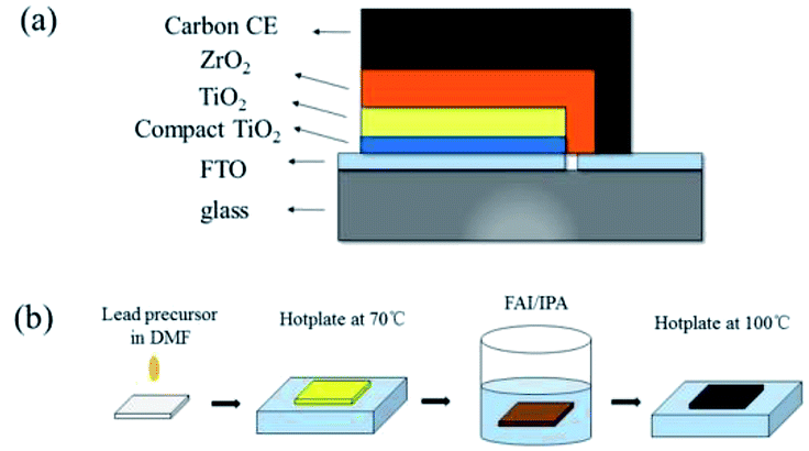 | ||
| Fig. 1 (a) The schematic of a fully printable HTM-free mesoscopic PSCs with carbon CE; (b) the schematic of a two-step sequential deposition method. | ||
The microstructures of the as-prepared devices can be observed using scanning electron microscopy (SEM) images of the cross-section. We can clearly find that each layer of the device showed well-defined boundaries and a uniform thickness (Fig. 2a). Through the EDS mapping, the triple layers from the top to the bottom can be identified as carbon, ZrO2, and TiO2. For the perovskite, Pb, I, Br, and Cs have a uniform distribution in the carbon/ZrO2/TiO2 layers, indicating a good filling of perovskite in the mesopores.
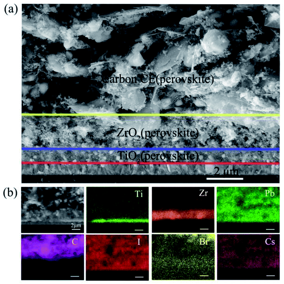 | ||
| Fig. 2 (a) The cross-sectional view of the SEM image of the carbon-based PSCs; (b) the corresponding EDS mapping. | ||
To study the influence of the Cs cation and Br ion in the crystal structure of the FAPbI3 perovskite, we introduced CsI, PbBr2, and CsBr with different mole ratios into the PbI2 solution. X-ray diffraction (XRD) measurements were used to identify the crystal structure of the as-prepared perovskite samples. The pure FAPbI3 exhibited a series of diffraction peaks at 2θ = 13.8°, 20°, 24.2°, 28°, 31°, 40°, and 42.7°, corresponding to the (111), (120), (021), (222), (231), (240), and (333) crystal planes of the α-FAPbI3 perovskite (Fig. 3). Moreover, a small diffraction peak at 2θ = 11.7° can be detected, indicating the existence of δ-FAPbI3.25 With the increase in Br, the δ-FAPbI3 showed a declining trend. Moreover, when the Br ratio came to 10%, there was no obvious peak of δ-FAPbI3. Similarly, the introduction of Cs could also restrain the generation of δ-FAPbI3.
 | ||
| Fig. 3 XRD pattern of the FAPbI3-based PSCs. | ||
To further investigate the effect of Br and Cs on the stability of the FAPbI3 perovskite, we stored all the samples in ambient air at 25 °C at a relative humidity (RH) of 50% and measured their XRD patterns every few days (7 days) to record the changes. As shown in Fig. S1a–h,† after 7 days, the peak of δ-FAPbI3 emerged from all of the samples except the one with 10% of CsBr. Moreover, after 14 days, the FAPbI3–10% CsBr sample still maintained the black α phase, while other samples had an obvious increase in the δ phase.
Hence, we can conclude that though both Cs and Br could inhibit the transformation of the FAPbI3 perovskite from α phase to δ phase, only the coexistence of Cs and Br could actually enhance the stability of the FAPbI3 perovskite (Fig. 3).
The optical properties of the FAPbI3-based perovskite films with different content of Br and Cs were measured by the UV-vis spectra and steady-state photoluminescence (PL) spectra. As shown in Fig. 4a, with the increase in the content of Br, the absorption edge of the samples had an obvious blue-shift, which is in good agreement with the theoretical calculations.7 Moreover, all the samples exhibited a slight enhancement of light absorption from 650 nm to 750 nm. For the samples with Cs, a slight blue-shift can be observed, manifesting the limited effect of Cs on the band gap of the FAPbI3 perovskite. Unlike Br, the introduction of Cs could significantly enhance the light absorption of the FAPbI3 perovskite from 650 nm to 750 nm. Note that the FAPbI3 perovskite with both Br and Cs showed the strongest absorbance from 650 nm to 750 nm among all the samples (Fig. 4c). Steady-state PL spectra measurements were also obtained for the perovskite samples loaded in the ZrO2/glass substrate. The emission peak of the Br-based FAPbI3 perovskite shifted from 807 nm to 798 nm as the Br ratio increased from 5% to 15% (Fig. 4b). Furthermore, the blue shifting of the Cs-based FAPbI3 perovskite was more inconspicuous (from 809 nm to 805 nm as the Cs ratio increased from 5% to 15%) than that of Br (Fig. 4d). These results are in good agreement with the UV-vis results.
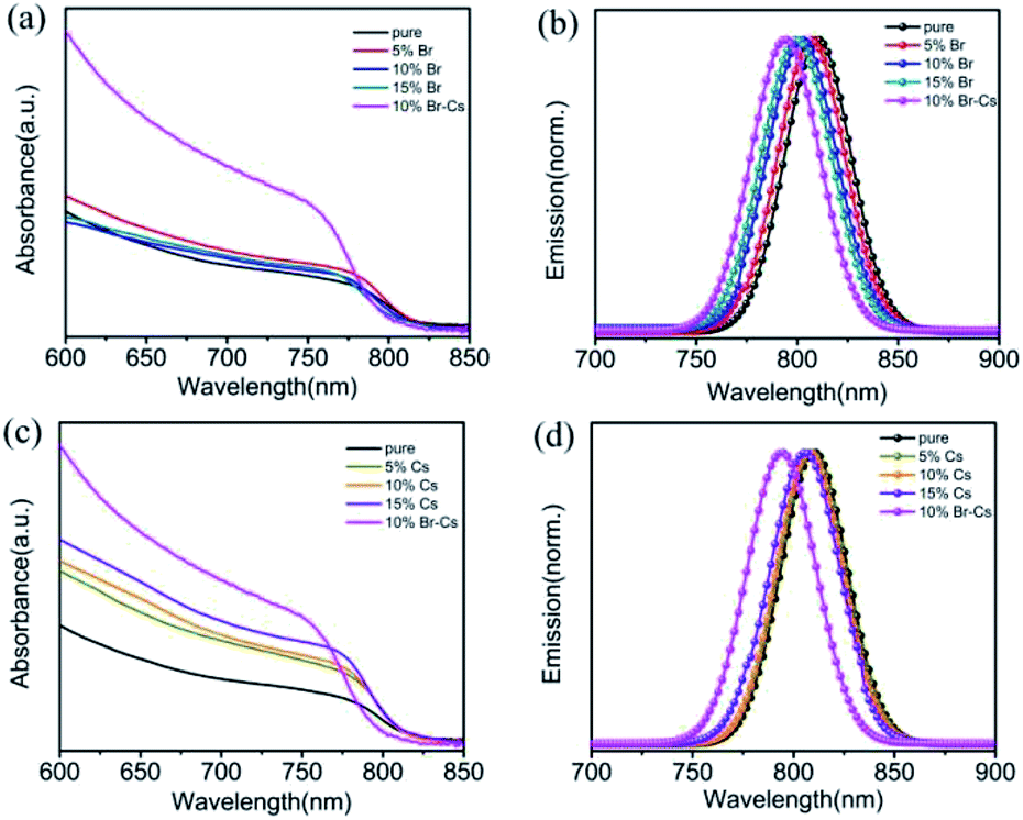 | ||
| Fig. 4 UV-vis and PL spectra of the FAPbI3-based films with different amounts of (a and b) Br and (c and d) Cs. | ||
Carbon-based PSCs with these different FAPbI3-based perovskites were measured under standard AM 1.5 illumination. After optimization (see Tables S1 and S2†), we found that the device with 10% Br or 10% Cs possessed higher PCE than that with other ratios. To ensure that the improvement of PCE is repeatable, four batches of PSCs (each consists of 15 devices) were fabricated using pristine FAPbI3, FAPbI3 with 10% of Br, FAPbI3 with 10% of Cs and FAPbI3 with 10% of Br–Cs, respectively. The detailed J–V performances are presented in Fig. S2,† and we found that the average PCE value of the devices was improved by introducing Br and Cs into FAPbI3.
To find out how Br and Cs affect the performance of the FAPbI3-based PSCs, we compared the champion devices with 10% Br, 10% Cs and 10% Cs–Br. As shown in Fig. 5a, the device with pristine FAPbI3 perovskite possessed an open circuit voltage (Voc) of 929 mV, a short circuit current density (Jsc) of 20.53 mA cm−2 and a fill factor (FF) of 0.567, yielding an overall PCE of 10.81%. By introducing 10% of Br, the FAPbBr0.1I2.9-device exhibited a slightly higher Voc (958 mV) and FF (0.593) than that of the pristine one, which resulted in a PCE of 11.53%. The Cs0.1FA0.9PbI3-device showed similar J–V parameters with the FAPbBr0.1I2.9-based one. Interestingly, the Cs0.1FA0.9PbBr0.1I2.9-device showed obvious enhancement in Voc (1018 mV), Jsc (22.16 mA cm−2) and FF (0.627) in comparison to the other device and exhibited a champion PCE of 14.14% (see Table 1 for the detail parameters). The steady current output of the device was maintained at 18.5 mA cm−2 for 2 min (see Fig. S3†). External quantum efficiency (EQE) measurement was used to verify the improvement of Jsc. As shown in Fig. 5b, the Cs0.1FA0.9PbBr0.1I2.9-device had a much higher EQE value than other ones in the range from 500 nm to 800 nm. The integrated Jsc of Cs0.1FA0.9PbBr0.1I2.9-device reached 22.0 mA cm−2, which is highly consistent with the J–V results.
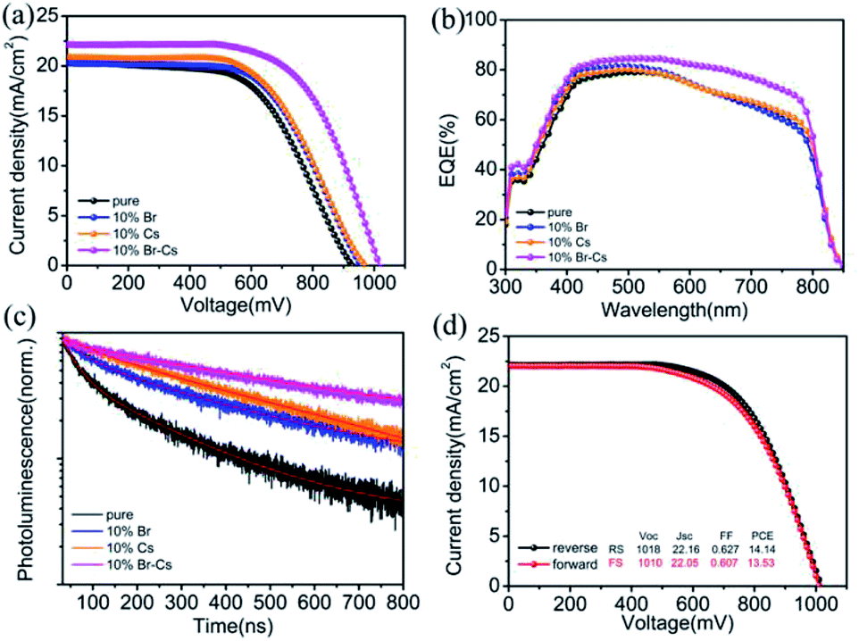 | ||
| Fig. 5 (a) Photocurrent density–voltage (J–V) curves of different FAPbI3-based PSCs; (b) the corresponding EQE; (c) TRPL spectra of different FAPbI3-based perovskite films; (d) J–V curves of Cs0.1FA0.9PbBr0.1I2.9-device under forward and reverse scan. | ||
| Composition | Voc (mV) | Jsc (mA cm−2) | FF | PCE(%) |
|---|---|---|---|---|
| Pristine | 929 | 20.53 | 0.567 | 10.81 |
| 10% Br | 958 | 20.29 | 0.593 | 11.53 |
| 10% Cs | 970 | 20.91 | 0.578 | 11.72 |
| 10% Br–Cs | 1018 | 22.16 | 0.627 | 14.14 |
Time-resolved photoluminescence (TRPL) was performed with an excitation wavelength of 780 nm to investigate the recombination behaviour between the electron and hole in the FAPbI3-based perovskite. In comparison to the pristine FAPbI3 perovskite, other samples with Br or Cs showed a longer electron life time (see Table S3† for the detail fitting parameters), which can be attributed to the better crystal quality. We deduced that the trap state density in pristine FAPbI3 is pretty high because of the phase transition. By introducing Br and Cs into the crystal, the structure of the FAPbI3 perovskite became more stable, and as a result, the trap state density was reduced. Apparently, the Cs0.1FA0.9PbBr0.1I2.9 crystal possessed the best phase stability and the lowest trap state density. Moreover, the J–V hysteresis of the Cs0.1FA0.9PbBr0.1I2.9-device remained at a low level (Fig. 5d), which also can provide evidence for our deduction.26
The long-term thermal stability measurements of FAPbI3-based PSCs were performed in an environmental chamber (Weiss SC3 600 MHG). At a constant temperature of 85 °C and 20% relative humidity (RH) condition, the device with the pristine FAPbI3 perovskite lost >60% (from 100% to 35.8%) of the initial PCE value after 500 h (Fig. 6a). However, the device with the Cs0.1FA0.9PbBr0.1I2.9 perovskite showed a pleasant long-term stability and maintained 90% of its initial PCE value (from 100% to 90.2%). At a RH 50% condition, the Cs0.1FA0.9PbBr0.1I2.9-device also showed a strong moisture resistance (see Fig. S4†). To further evaluate the long-term stability of the device under practical thermal stress, we also performed the thermal cycling test on the devices. First, the encapsulated devices were loaded in the environmental chamber and stabilized at 25 °C. Then, the chamber was heated up to 85 °C for 25 min, and chilled down to −30 °C for 25 min. After 100 cycles, the Cs0.1FA0.9PbBr0.1I2.9 device had no obvious decay in the PCE value, manifesting its superior stability under thermal stress.
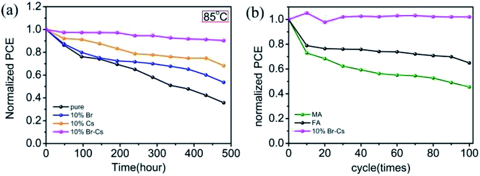 | ||
| Fig. 6 The thermal stability measurements of FAPbI3-based PSCs at (a) a constant temperature of 85 °C and 20% RH in dark condition; (b) thermal cycling from −30 °C to 85 °C. | ||
Conclusions
In summary, we comprehensively studied the effect of the Br and Cs ions on the performance of carbon-based PSCs with the FAPbI3 perovskite. By regulating the content of Br and Cs, we obtained a high PCE up to 14.14% on the PSC device with the Cs0.1FA0.9PbBr0.1I2.9 perovskite. Moreover, the as-prepared device exhibited an outstanding stability against humidity and heat. Without encapsulation, the device maintained 87% of its initial PCE under 50% RH after 120 days, and the PCE only decreased by about 10% after 480 h at 85 °C. Thermal cycling tests were also performed on these carbon-based devices. According to the results, the CsxFA1−xPbBrxI3−x perovskite showed superior stability than the FAPbI3 and MAPbI3 perovskites in the carbon-based PSCs. This study may provide a certain reference value to the practical application of low-cost, high-efficiency PSCs.Conflicts of interest
There are no conflicts to declare.Acknowledgements
The authors acknowledge the financial support by National Natural Science Foundation of China (NSFC 51702243), the Technological Innovation Key Project of Hubei Province (2018AAA048), the Fundamental Research Funds for the Central Universities (WUT: 2016IVA093, 2016IVA089, 2016IVA085, 2016III030, 2017III022, 2018IVB031) and Hubei Key Laboratory of Low Dimensional Optoelectronic Material and Devices (HLOM151001).Notes and references
- A. Kojima, K. Teshima, Y. Shirai and T. Miyasaka, J. Am. Chem. Soc., 2009, 131, 6050–6051 CrossRef CAS PubMed.
- N. R. E. L., Best Research Cell_Efficiencies, July 2018, https://www.nrel.gov/pv/cell-efficiency.html Search PubMed.
- G. Grancini, C. Roldán-Carmona, I. Zimmermann, E. Mosconi, X. Lee, D. Martineau, S. Narbey, F. Oswald, F. De Angelis, M. Graetzel and M. K. Nazeeruddin, Nat. Commun., 2017, 8, 15684 CrossRef CAS PubMed.
- J. M. Frost, K. T. Butler, F. Brivio, C. H. Hendon, M. van Schilfgaarde and A. Walsh, Nano Lett., 2014, 14, 2584–2590 CrossRef CAS PubMed.
- T. Baikie, Y. Fang, J. M. Kadro, M. Schreyer, F. Wei, S. G. Mhaisalkar, M. Graetzel and T. J. White, J. Mater. Chem. A, 2013, 1, 5628 RSC.
- A. K. Baranwal, S. Kanaya, T. A. Peiris, G. Mizuta, T. Nishina, H. Kanda, T. Miyasaka, H. Segawa and S. Ito, ChemSusChem, 2016, 9, 2604–2608 CrossRef CAS PubMed.
- C. Yi, J. Luo, S. Meloni, A. Boziki, N. Ashari-Astani, C. Grätzel, S. M. Zakeeruddin, U. Röthlisberger and M. Grätzel, Energy Environ. Sci., 2016, 9, 656–662 RSC.
- N. Pellet, P. Gao, G. Gregori, T.-Y. Yang, M. K. Nazeeruddin, J. Maier and M. Grätzel, Angew. Chem., Int. Ed., 2014, 53, 3151–3157 CrossRef CAS PubMed.
- J.-W. Lee, D.-J. Seol, A.-N. Cho and N.-G. Park, Adv. Mater., 2014, 26, 4991–4998 CrossRef CAS PubMed.
- J.-F. Liao, W.-Q. Wu, Y. Jiang, D.-B. Kuang and L. Wang, Sol. RRL, 2019, 3, 1800268 CrossRef.
- W.-Q. Wu and L. Wang, Adv. Funct. Mater., 2018, 28, 1804356 CrossRef.
- A. K. Jena, M. Ikegami and T. Miyasaka, ACS Energy Lett., 2017, 2, 1760–1761 CrossRef CAS.
- K. Domanski, J.-P. Correa-Baena, N. Mine, M. K. Nazeeruddin, A. Abate, M. Saliba, W. Tress, A. Hagfeldt and M. Grätzel, ACS Nano, 2016, 10, 6306–6314 CrossRef CAS PubMed.
- Z. Ku, Y. Rong, M. Xu, T. Liu and H. Han, Sci. Rep., 2013, 3, 3132 CrossRef PubMed.
- J. Luo, J. Chen, B. Wu, T. W. Goh, W. Qiao, Z. Ku, H. B. Yang, L. Zhang, T. C. Sum and B. Liu, Chem, 2018, 4, 911–923 CAS.
- L. Wagner, S. Chacko, G. Mathiazhagan, S. Mastroianni and A. Hinsch, ACS Energy Lett., 2018, 3, 1122–1127 CrossRef CAS.
- G. Huang, C. Wang, H. Zhang, S. Xu, Q. Xu and Y. Cui, J. Mater. Chem. A, 2018, 6, 2449–2455 RSC.
- C.-M. Tsai, G.-W. Wu, S. Narra, H.-M. Chang, N. Mohanta, H.-P. Wu, C.-L. Wang and E. W.-G. Diau, J. Mater. Chem. A, 2017, 5, 739–747 RSC.
- H. Zhang, H. Wang, S. T. Williams, D. Xiong, W. Zhang, C.-C. Chueh, W. Chen and A. K.-Y. Jen, Adv. Mater., 2017, 29, 1606608 CrossRef PubMed.
- A. Priyadarshi, L. J. Haur, P. Murray, D. Fu, S. Kulkarni, G. Xing, T. C. Sum, N. Mathews and S. G. Mhaisalkar, Energy Environ. Sci., 2016, 9, 3687–3692 RSC.
- Y. Rong, X. Hou, Y. Hu, A. Mei, L. Liu, P. Wang and H. Han, Nat. Commun., 2017, 8, 14555 CrossRef PubMed.
- A. Mei, X. Li, L. Liu, Z. Ku, T. Liu, Y. Rong, M. Xu, M. Hu, J. Chen, Y. Yang, M. Gratzel and H. Han, Science, 2014, 345, 295–298 CrossRef CAS PubMed.
- Y. Sheng, Y. Hu, A. Mei, P. Jiang, X. Hou, M. Duan, L. Hong, Y. Guan, Y. Rong, Y. Xiong and H. Han, J. Mater. Chem. A, 2016, 4, 16731–16736 RSC.
- J. Burschka, N. Pellet, S. J. Moon, R. Humphry-Baker, P. Gao, M. K. Nazeeruddin and M. Gratzel, Nature, 2013, 499, 316–319 CrossRef CAS PubMed.
- A. Binek, F. C. Hanusch, P. Docampo and T. Bein, J. Phys. Chem. Lett., 2015, 6, 1249–1253 CrossRef CAS PubMed.
- H. Jiang, X. Liu, N. Chai, F. Huang, Y. Peng, J. Zhong, Q. Zhang, Z. Ku and Y.-b. Cheng, RSC Adv., 2018, 8, 35157–35161 RSC.
Footnote |
| † Electronic supplementary information (ESI) available. See DOI: 10.1039/c9ra00043g |
| This journal is © The Royal Society of Chemistry 2019 |