 Open Access Article
Enhanced catalytic activity of Au core Pd shell Pt cluster trimetallic nanorods for CO2 reduction†
Lan-qi He,
Hao Yang,
Jia-jun Huang,
Xi-hong Lu ,
Gao-Ren Li
 ,
Xiao-qing Liu*,
Ping-ping Fang
 * and
Ye-xiang Tong
 *
*
KLGHEI of Environment and Energy Chemistry, MOE of the Key Laboratory of Bioinorganic and Synthetic Chemistry, The Key Lab of Low-Carbon Chemistry and Energy Conservation of Guangdong Province, School of Chemistry, Sun Yat-Sen University, Guangzhou 510275, China. E-mail: liuxiaoq5@mail.sysyu.edu.cn; fangpp3@mail.sysu.edu.cn; chedhx@mail.sysu.edu.cn
First published on 1st April 2019
Abstract
Herein, Au core Pd shell Pt cluster nanorods (Au@Pd@Pt NRs) with enhanced catalytic activity were rationally designed for carbon dioxide (CO2) reduction. The surface composition and Pd–Pt ratios significantly influenced the catalytic activity, and the optimized structure had only a half-monolayer equivalent of Pt (θPt = 0.5) with 2 monolayers of Pd, which could enhance the catalytic activity for CO2 reduction by 6 fold as compared to the Pt surface at −1.5 V vs. SCE. A further increase in the loading of Pt actually reduced the catalytic activity; this inferred that a synergistic effect existed among the three different nanostructure components. Furthermore, these Au NRs could be employed to improve the photoelectrocatalytic activity by 30% at −1.5 V due to the surface plasmon resonance. An in situ SERS investigation inferred that the Au@Pd@Pt NRs (θPt = 0.5) were less likely to be poisoned by CO because of the Pd–Pt bimetal edge sites; due to this reason, the proposed structure exhibited highest catalytic activity. These results play an important role in the mechanistic studies of CO2 reduction and offer a new way to design new materials for the conversion of CO2 to liquid fuels.
Introduction
Carbon dioxide (CO2) is a greenhouse gas released by both natural and artificial processes and causes a number of environmental problems,1,2 which have driven extensive research interest in CO2 reduction catalysis;3 in this regard, the electrochemical reduction of CO2 into useful fuels in an aqueous solution has attracted significant attention because it is environmentally clean and the products obtained can be stored in the form of chemical energy.4 The most commonly explored electrocatalysts for CO2 reduction are transition metal elements5 and their alloys6,7 such as bimetals8 or trimetals.9 This is probably because these metals have vacant orbitals and active d-electrons, which are believed to energetically facilitate the adsorption and desorption bonding between the metal and the CO2 forming products; however, the electrochemical CO2 reduction reaction suffers from poor efficiency due to the requirement of a large over potential, CO poisoning and so on.10 The mechanism of this reaction is still not clearly understood, and the intermediates and other reaction steps have also been discussed controversially. Therefore, it is necessary to design new catalysts with high efficiency that are less likely to be poisoned by CO.11Indeed, novel heterogeneous nanocatalysts with optimized characteristics are usually achieved by rationally tuning their compositions and nanostructures. Several reviews have been recently reported to address the significance of these designs.12,13 Interestingly, in recent years, in addition to compositions,14 morphology adjustments,15 and structure interface,16 surface plasmon resonance (SPR) has emerged as another highly important factor and useful strategy to regulate the activities of the nanocatalysts.17,18 For nanocatalysts consisting of plasmonic metals (such as Au, Ag, and Cu), the electric field aroused by SPR can directly enhance the catalytic activity. In addition, the light energy can be effectively coupled with these nanocrystals because the hot-electrons induced by illumination can function as carriers to convert the light energy into chemical energy, and thus, enhancement in the photocatalytic ability can be achieved.19 Compared with their monometallic and bimetallic counterparts, trimetallic nanocomposites embedded within a plasmonic metal core exhibit remarkable advantages as their catalytic characteristics are better tailored. This is because their catalytic properties can be divided into two parts: the photocatalytic activity resulting from the SPR core and the electrocatalytic activity stemming from the bimetal surface coating. As a consequence, by finely tuning their nanoarchitectures, compositions, or particle sizes, it is possible to obtain trimetallic nanocrystals with optimal catalytic activity for various important chemical reactions.
Herein, we report Au core Pd shell Pt cluster nanorods (Au@Pd@Pt NRs) with enhanced electrocatalytic and photocatalytic activity for CO2 reduction. By subtly controlling the atom monolayers of the Pt clusters, we obtained ideal Au core Pd shell Pt cluster nanorods with optimized photoelectrocatalytic ability for the reduction of CO2. As abovementioned, the enhancement in the photocatalytic activity should be attributed to the SPR phenomenon resulting from the plasmonic Au core. A synergistic effect between the Pd shell and the Pt clusters was demonstrated by systematic investigation of the influence of the thickness of the Pt coverage on the electroreduction of CO2. Furthermore, in situ surface enhanced Raman spectrum (SERS) was obtained to study the mechanism of CO2 reduction and investigate the active site.
Results and discussion
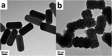
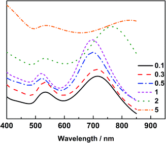
The Au@Pd@Pt NRs were freshly prepared according to our previously reported method with slight modifications (see the details in the Experimental section of the ESI†). Generally, the thickness of Pd was maintained at 2 layers on the 49 nm Au core, and the Pt coverage on Au@2Pd was varied from 0.1 to 5 layers (hereinafter denoted as θPt) by finely tuning the amount of H2PtCl6 used during the reduction process. The as-prepared nanocrystals were first characterized by a transmission electron microscope (TEM) (Fig. S1 in ESI†). The Au@Pd@Pt NRs show a quite uniform size distribution, and the Pt clusters can only be clearly seen on the surface when they are sufficiently thick, with a Pt coverage of 5 layers for instance (Fig. 1); similar structures for the Au@Pd@Pt NRs have been reported in our previous studies.20 To verify the existence of Pt, we obtained the cyclic voltammograms of various Au@2Pd with different Pt coverages in 0.5 M H2SO4. With an increase in the Pt coverage thickness, the typical oxygen desorption peak shifted to more positive values; this demonstrated that the electrochemical properties of these NRs switched from those of Pd to those of Pt (Fig. S2 in ESI†). Elemental analysis by ICP-AES also confirmed the effective coating of Pt on the Au@2Pd surface (Table S1 in ESI†).The optical properties of Au@Pd@Pt NRs were then investigated by UV-Vis spectroscopy (Fig. 2). As observed, all Au@Pd@Pt NRs had two absorption peaks at ca. 530 nm and ca. 700 nm. The shorter peak at 530 nm was caused by transverse SPR absorption, whereas the longer peak at 700 nm corresponded to longitudinal SPR absorption. The two absorption peaks experienced a slight blue-shift and gradually damped with an increase in the Pt coverage from 0.1 to 5 layers. These spectral behaviours reasonably inferred that the total optical properties of the core–shell–cluster nanostructures changed from core dominant to shell cluster dominant.21
The catalytic performance of different nanocatalysts for CO2 reduction was then investigated by linear sweep voltammetry (LSV) in 0.1 M KHCO3 saturated with CO2 gas. We found that the introduction of Pt on the Au@Pd surface led to an improved catalytic performance for CO2 electroreduction, and the trimetallic nanocatalyst exhibited higher catalytic activity as compared to Au@Pt nanoparticles. It is thus highly probable that a synergistic effect exists in the trimetallic nanocomposites (Fig. S3 in the ESI†).
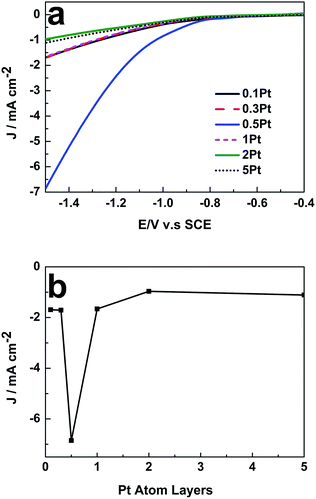
To verify this viewpoint, LSV was further employed to reveal the influence of θPt on the catalytic activity of the 49 nm Au@Pd@Pt NRs toward CO2 electroreduction. As shown in Fig. 3a, with a fixed Au NR core and a Pd-shell thickness of about 2 monolayers, the catalytic activity of the core–shell–cluster NRs for CO2 reduction was remarkably dependent on θPt. The highest catalytic activity was achieved when θPt was at about 0.5, which was about 6-fold at −1.5 V vs. saturated calomel electrode (SCE) than that obtained at the θPt of 0.1 or 5 (Fig. 3b). A further increase in the loading of Pt actually decreased the catalytic activity; this confirmed that a synergistic effect existed among the three different nanostructure components. Cai et al. also found that the Pd–Pt bimetal surface exhibited higher catalytic activity towards CO2 reduction than its monometallic counterpart. However, they did not optimize the Pd and Pt composition.22 They also proved that the Pd–Pt bimetal could significantly reduce the production of H2 and enhance CO2 reduction.23 The 49 nm Au@Pd@Pt NRs exhibited maximum catalytic activity when θPt was 0.5; this implied that the ratio of their Pt-cluster to Pd shell was optimal for the electroreduction of CO2. This core–shell–cluster nanostructure is completely different from other bimetallic and trimetallic alloy/composite nanostructures because the proportions of the core, shell and cluster can be subtly tuned independently to utilize the synergistic effect for maximum enhancement.
We then investigated the impact of light exposure duration on the photocatalytic activity. As presented in Fig. 4a, the catalytic activity of Au@Pd@Pt NRs gradually increased with an increase in the illumination time in the first 20 min and then remained constant. The surface temperature of the nanocatalysts with Au cores could reach higher than 95 °C by constant light irradiation over 20 min, accelerating the chemical reaction rate by heating, as demonstrated in our previous study.18 Indeed, 20 min light irradiation resulted in ca. 30% enhancement in the catalytic activity at −1.5 V vs. SCE. This improvement in the catalytic performance might be caused by the photoelectronic and photothermal effect induced by the SPR of the Au core.
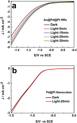 | ||
| Fig. 4 Influence of the illumination time on the LSV curves of (a) 49 nm Au@Pd@Pt NRs and (b) Pd@Pt nanocubes in 0.1 M KHCO3 (pH = 6.8) θPt = 0.5; scan rate: 50 mV s−1. | ||
When the Pt coverage became thicker, the SPR of the 49 nm Au@Pd@Pt NRs was greatly blocked due to the decreased surface area of the Au core exposed to the illumination, and it thus weakened the enhancement of the photocatalytic activity (Fig. S4 in ESI†). Moreover, to verify that the SPR effect played a vital role in the improvement of the catalytic performance, control experiments were conducted on Pd nanocubes coated by Pt clusters. Note that no SPR effect could be detected since Au was absent in this nanomaterial. By comparing the LSV curves obtained with and without 20 min light illumination, we found that light irradiation did not impact the electrocatalytic process of CO2 on these Pd@Pt nanocubes (Fig. 4b). Therefore, the enhancement of the photocatalytic activity of the Au@Pd@Pt nanocrystals should be ascribed to the SPR effect from the Au core, as expected.
Finally, the CO2 reduction mechanism on the 49 nm Au@Pd@Pt NRs was studied by in situ SERS. CO is an inevitable intermediate in the CO2 electroreduction to produce hydrocarbons or alcohols.24 Therefore, herein, we mainly studied the SERS signal of CO and investigated how CO affected the catalytic activity in our system.
The Raman shift between 2020 and 2090 cm−1 corresponded to the on-top adsorption of CO on Pt,25 whereas the Raman shift between 1900 and 2000 cm−1 was assigned to the bridge adsorption of CO.26 We observed that the on-top adsorption of CO gradually increased with a decrease in the applied potential and finally disappeared at −1.0 V. No bridge adsorption of CO was detected in the potential region studied herein (Fig. 5). It has been reported that CO has high adsorption energy on separate Pt atoms; this causes easy poisoning of the separate Pt atoms; on the other hand, due to the low adsorption energy at the Pd–Pt edge sites, these sites are not easily poisoned by CO.27 We thus believe that CO2 is reduced to CO on the Pt atoms only and not on the Pd or Pd–Pt bridge atoms. Namely, the Pd–Pt edge sites that were not easily poisoned by CO were the active sites for CO2 reduction, whereas the separated Pt atoms were easily poisoned by CO. Therefore, the increase in the Pd–Pt edge site density could greatly increase the catalytic activity. When θPt was about 0.5, the Pd–Pt edge site density was maximum, and therefore, the electrocatalytic activity became highest with θPt at about 0.5, as shown in Fig. 3; moreover, when the potential decreased to −1.0 V, the CO peak disappeared, and the peak intensity representing the C–H stretching (at 2800–2970 cm−1) increased immediately;28 this suggested that CO was further reduced to the hydrocarbon products after −1.0 V.
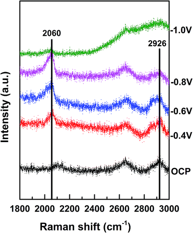 | ||
| Fig. 5 In situ Raman spectra of Au@2Pd@0.5Pt NRs in 0.1 M KHCO3 (pH = 6.8) at different potentials (vs. SCE). | ||
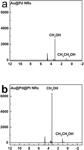
We further analysed the products of CO2 reduction by the Au@Pd@Pt NRs using nuclear magnetic resonance (NMR). To be specific, chronoamperometry was first conducted under a constant potential at −0.6 V for 2 h, and the content of the electrolyte solution was then tested by NMR. Interestingly, we found that the trimetallic Au@Pd@Pt NRs were prone to converting CO2 into liquid products including methanol and ethanol (Fig. 6); this was in accordance with our Raman results (C–H stretching at 2800–2970 cm−1). Moreover, a larger amount of the liquid products was detected using Au@2Pd@0.5Pt NRs as compared to that obtained using Au@2Pd NRs under the same experimental conditions. Furthermore, the reduction velocity for the Au@2Pd@0.5Pt NRs is three times that for the Au@2Pd NRs. There was also some ethanol among the products. Indeed, the transformation of CO2 to alcohols, especially ethanol, by noble metals has been seldom reported, and the interesting results reported in this study indicate that the trimetallic nanostructure is favourable to the electrocatalytic transformation of CO2 to alcohols due to the synergistic effect of the trimetallic nanocrystals.
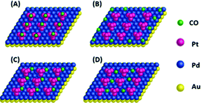
In our previous study, we found 4 possible reactive sites (Fig. 7) on the Pd–Pt bimetal surface on the Au core by DFT calculation.27 Indeed, the A, B and C sites could adsorb CO strongly, whereas the CO adsorption on the D site was quite weak.29 Therefore, the D site could not be poisoned by CO, whereas the A, B and C sites could be easily poisoned by CO. From the specific Raman shift of CO2 reduction by the Au@Pd@Pt NRs in our experiments (Fig. 5), we only observed an on-top adsorption of CO on the Au@Pd@Pt NPs; this suggested that only the A site was easily poisoned by CO during CO2 reduction, whereas the B, C and D sites were possible active sites for CO2 reduction on the Au@Pd@Pt NR surface. According to the literature, CO2 was not easily reduced to CO on the separate Pd sites.30 As a result, the B and C Pd–Pt bridge sites were the possible active centres for CO2 reduction. The B and C sites reached their maximum density when the Pt coverage was about 0.5, which caused the highest catalytic activity. Wang et al. found that the Pd–Pt edges/ridges in the catalyst exhibited optimal catalytic activity.31 The catalytic performance was thus closely related to the number of Pd–Pt edge sites; this indicated that the ratio of Pd to Pt greatly influenced the CO2 reduction activity.
Experimental
Chemicals and materials
Water purified with a Milli-Q system (resistivity of 18.2 MΩ cm at 25 °C) was used throughout the study. PdCl2 (99%), HAuCl4 (99%) and H2PtCl6 (99%) were purchased from Alfa Aesar. Unless stated, all the other chemicals were of analytical grade and obtained from Shanghai Reagent Co. of Chinese Medicine. The F-doped tin oxide (FTO) glass was bought from the NSG Group. FTO glass slides (20 mm × 10 mm × 0.22 mm) were selected for working electrode fabrication to afford the low electrical resistance of 14 ohm and high transparency (≥90%).Synthesis of the Au@Pd@Pt NRs
The Au NRs were synthesized according to a procedure reported in the literature18,32 with slight modification, whereas the Pd and Pt coverage layers were coated above the Au core based on our previous study.27 Briefly, to coat a Pd shell of about 2 monolayers on the Au NRs, 1 ml of 1 mM H2PdCl4 and 0.5 ml of 10 mM ascorbic acid were mixed with the Au core solution and stirring was continued at 30 °C for 30 min. To coat Au@Pd with Pt clusters of different thicknesses, various volumes of 10 mM ascorbic acid and 1 mM H2PtCl6 were subsequently added to the as-prepared solution at 80 °C, and stirring was continued for 30 min. However, we added 25% additional H2PtCl6 to the solution during each synthesis to ensure the corresponding Pt coverage according to the literature.27 The nanocrystal solution was centrifuged and washed 3 times with water before use (see the synthetic details in the ESI†).It was necessary to mention that Pt grew on Pd as a set of clusters and not as consecutive monolayers; however, we used monolayer-equivalents as a convenient way to describe the amount of Pt added to the Au@Pd nanocomposite.
Preparation of the working electrode
The FTO glass substrates were thoroughly cleaned with ethanol and acetone, washed with water, and then used to afford the nanocatalysts. A certain amount of the trimetallic nanocatalyst solution that ensured coverage of about a monolayer of the NPs on the 20 mm × 10 mm FTO pieces (20% loss occurred during centrifugation) was centrifuged three times, dropped onto the FTO substrate and dried to act as the working electrode. The electrochemical active surface area (ECSA) of the working electrode was calculated according to the hydrogen adsorption/desorption peaks and confirmed by the oxygen adsorption/desorption peaks for the Au@Pd@Pt NRs in 0.5 M H2SO4 (Fig. S2 in ESI†).33 The measured currents were normalized by the ECSA values to evaluate the catalytic performance of different nanocatalysts.Electrochemical measurements and spectroelectrochemical studies
Electrochemical measurements were performed using the CHI 760E electrochemical workstation (CH Instruments, China). The CO2 reduction reaction was studied in a three-electrode photoelectrochemical cell with a Pt wire and a SCE as the counter and the reference electrodes, respectively. The catalytic activity of CO2 reduction was investigated by linear sweep voltammetry (LSV), and 0.1 M KHCO3 (pH = 6.8) was used as the electrolyte solution. The investigation of the light influence was achieved using a xenon lamp as the light source (LCS-100, ORIEL, Newport). The intensity of the incident light was always maintained at 100 mW cm−2 during the photoelectrochemical test. Raman spectra were obtained using a laser micro-Raman spectrometer (Renishaw in Via) with an excitation wavelength at 632.8 nm from a He–Ne laser, and in situ EC-SERS measurements were performed in the photoelectrochemical cell.Characterization
TEM images were acquired using Tecnai T12 (FEI, The Netherlands) with an operation voltage of 120 kV, and the UV-Vis absorption spectra were obtained by the Shimadzu UV-2450 Spectrophotometer.Conclusions
We designed Au core Pd shell Pt cluster NRs with enhanced catalytic activity and photocatalytic activity for CO2 reduction. The improvement in the catalytic activity was obtained by tuning the Pt coverage on Pd, and the highest catalytic activity was achieved when θPt was about 0.5. In situ SERS further confirmed that CO2 was reduced to CO only on the Pt top sites and not on the Pd–Pt edge sites. Therefore, the Pd–Pt edge sites were the electroactive centres of the Au@Pd@Pt NRs for the transformation of CO2 to liquid products. These Pd–Pt edge sites reached highest density when θPt was about 0.5, leading to optimal catalytic activity. Moreover, owing to the SPR from the Au core, the catalytic activity could be further enhanced by 30% with light illumination. In summary, the Au core Pd shell Pt cluster NR structure not only takes advantage of the Pd–Pt bimetal surface to improve the electrocatalytic ability, but also utilizes the Au core with SPR to improve the photocatalytic activity. This study sheds light on the CO2 reduction mechanism on the trimetallic nanocrystals and offers an innovative idea to design a series of new catalysts with better catalytic properties to convert CO2 to liquid fuels such as methanol and ethanol.Conflicts of interest
There are no conflicts to declare.Acknowledgements
This work was supported by the National Key Research and Development Program of China (2016YFA0202604), the Natural Science Foundation of China (21405182, 21802173 and 21773315), the Science and Technology Plan Project of Guangdong Province (2015B010118002), the Guangdong Province Universities and Colleges Pearl River Scholar Funded Scheme (2017), the Natural Science Foundation of Guangdong Province (No. 2018A030310301), the Pearl River S&T Nova Program of Guangzhou (201710010019), the Fundamental Research Funds for the Central Universities (17lgjc36) and the Guangdong Provincial Key Platform and Major Scientific Research Projects for Colleges and Universities (2015KCXTD029).Notes and references
- J. Ran, M. Jaroniec and S.-Z. Qiao, Adv. Mater., 2018, 30, 1704649 CrossRef PubMed.
- L. Zhang, Z.-J. Zhao, T. Wang and J. Gong, Chem. Soc. Rev., 2018, 5423–5443 RSC.
- H. Mistry, A. S. Varela, C. S. Bonifacio, I. Zegkinoglou, I. Sinev, Y. W. Choi, K. Kisslinger, E. A. Stach, J. C. Yang, P. Strasser and B. R. Cuenya, Nat. Commun., 2016, 7, 12123 CrossRef PubMed.
- A. García-Trenco, E. R. White, A. Regoutz, D. J. Payne, M. S. P. Shaffer and C. K. Williams, ACS Catal., 2017, 7, 1186–1196 CrossRef.
- C. W. Li and M. W. Kanan, J. Am. Chem. Soc., 2012, 134, 7231–7234 CrossRef CAS PubMed.
- W. Luc, C. Collins, S. Wang, H. Xin, K. He, Y. Kang and F. Jiao, J. Am. Chem. Soc., 2017, 139, 1885–1893 CrossRef CAS PubMed.
- B. Kumar, J. P. Brian, V. Atla, S. Kumari, K. A. Bertram, R. T. White and J. M. Spurgeon, ACS Catal., 2016, 4739–4745 CrossRef CAS.
- G. Gao, Y. Jiao, E. R. Waclawik and A. Du, J. Am. Chem. Soc., 2016, 138, 6292–6297 CrossRef CAS PubMed.
- P. Frontera, A. Macario, A. Malara, S. Santangelo, C. Triolo, F. Crea and P. Antonucci, Catalysts, 2018, 8, 435 CrossRef.
- M.-J. Cheng, E. L. Clark, H. H. Pham, A. T. Bell and M. Head-Gordon, ACS Catal., 2016, 6, 7769–7777 CrossRef CAS.
- R. Ahmad and A. K. Singh, J. Mater. Chem. A, 2018, 6, 21120–21130 RSC.
- K. D. Gilroy, A. Ruditskiy, H. C. Peng, D. Qin and Y. N. Xia, Chem. Rev., 2016, 116, 10414–10472 CrossRef CAS PubMed.
- M. B. Gawande, A. Goswami, T. Asefa, H. Guo, A. V. Biradar, D.-L. Peng, R. Zboril and R. S. Varma, Chem. Soc. Rev., 2015, 44, 7540–7590 RSC.
- H. Sheng, M. H. Oh, W. T. Osowiecki, W. Kim, A. P. Alivisatos and H. Frei, J. Am. Chem. Soc., 2018, 140, 4363–4371 CrossRef CAS PubMed.
- S. Liu, H. Tao, L. Zeng, Q. Liu, Z. Xu, Q. Liu and J. L. Luo, J. Am. Chem. Soc., 2017, 139, 2160–2163 CrossRef CAS PubMed.
- D. Gao, Y. Zhang, Z. Zhou, F. Cai, X. Zhao, W. Huang, Y. Li, J. Zhu, P. Liu, F. Yang, G. Wang and X. Bao, J. Am. Chem. Soc., 2017, 139, 5652–5655 CrossRef CAS PubMed.
- C. Wang, X. G. Nie, Y. Shi, Y. Zhou, J. J. Xu, X. H. Xia and H. Y. Chen, ACS Nano, 2017, 11, 5897–5905 CrossRef CAS PubMed.
- H. Yang, Z. H. Wang, Y. Y. Zheng, L. Q. He, C. Zhan, X. H. Lu, Z. Q. Tian, P. P. Fang and Y. X. Tong, J. Am. Chem. Soc., 2016, 138, 16204–16207 CrossRef CAS PubMed.
- L. Zhang, M. Can, S. W. Ragsdale and F. A. Armstrong, ACS Catal., 2018, 8, 2789–2795 CrossRef CAS.
- H. Yang, L.-Q. He, Z.-H. Wang, Y.-Y. Zheng, X. Lu, G.-R. Li, P.-P. Fang, J. Chen and Y. Tong, Electrochim. Acta, 2016, 209, 591–598 CrossRef CAS.
- X. Liu, J. Iocozzia, Y. Wang, X. Cui, Y. Chen, S. Zhao, Z. Li and Z. Lin, Energy Environ. Sci., 2017, 10, 402–434 RSC.
- F. Cai, D. Gao, R. Si, Y. Ye, T. He, S. Miao, G. Wang and X. Bao, Electrochem. Commun., 2017, 76, 1–5 CrossRef CAS.
- F. Cai, D. Gao, H. Zhou, G. Wang, T. He, H. Gong, S. Miao, F. Yang, J. Wang and X. Bao, Chem. Sci., 2017, 8, 2569–2573 RSC.
- T.-T. Zhuang, Z.-Q. Liang, A. Seifitokaldani, Y. Li, P. De Luna, T. Burdyny, F. Che, F. Meng, Y. Min, R. Quintero-Bermudez, C. T. Dinh, Y. Pang, M. Zhong, B. Zhang, J. Li, P.-N. Chen, X.-L. Zheng, H. Liang, W.-N. Ge, B.-J. Ye, D. Sinton, S.-H. Yu and E. H. Sargent, Nature Catalysis, 2018, 1, 421–428 CrossRef.
- K. G. Schmitt and A. A. Gewirth, J. Phys. Chem. C, 2014, 118, 17567–17576 CrossRef CAS.
- N. Todoroki, H. Osano, T. Maeyama, H. Yoshida and T. Wadayama, Appl. Surf. Sci., 2009, 256, 943–947 CrossRef CAS.
- P.-P. Fang, S. Duan, X.-D. Lin, J. R. Anema, J.-F. Li, O. Buriez, Y. Ding, F.-R. Fan, D.-Y. Wu, B. Ren, Z. L. Wang, C. Amatore and Z.-Q. Tian, Chem. Sci., 2011, 2, 531–539 RSC.
- Y. Guo, O. Yaffe, D. W. Paley, A. N. Beecher, T. D. Hull, G. Szpak, J. S. Owen, L. E. Brus and M. A. Pimenta, Phys. Rev. Mater., 2017, 1, 042401 CrossRef.
- S. Duan, Y. F. Ji, P. P. Fang, Y. X. Chen, X. Xu, Y. Luo and Z. Q. Tian, Phys. Chem. Chem. Phys., 2013, 15, 4625–4633 RSC.
- R.-H. Guo, C.-F. Liu, T.-C. Wei and C.-C. Hu, Electrochem. Commun., 2017, 80, 24–28 CrossRef CAS.
- X. Wang, M. Vara, M. Luo, H. Huang, A. Ruditskiy, J. Park, S. Bao, J. Liu, J. Howe, M. Chi, Z. Xie and Y. Xia, J. Am. Chem. Soc., 2015, 137, 15036–15042 CrossRef CAS PubMed.
- H. Yang, L. Q. He, Y. W. Hu, X. Lu, G. R. Li, B. Liu, B. Ren, Y. Tong and P. P. Fang, Angew. Chem., Int. Ed., 2015, 54, 11462–11466 CrossRef CAS PubMed.
- J. C. Matsubu, V. N. Yang and P. Christopher, J. Am. Chem. Soc., 2015, 137, 3076–3084 CrossRef CAS PubMed.
Footnote |
| † Electronic supplementary information (ESI) available. See DOI: 10.1039/c8ra10494h |
| This journal is © The Royal Society of Chemistry 2019 |

