 Open Access Article
Facile efficient earth abundant NiO/C composite electrocatalyst for the oxygen evolution reaction†
Abdul Qayoom Mugheria,
Aneela Tahirab,
Umair Aftabc,
Muhammad Ishaq Abroc,
Saleem Raza Chaudhryd,
Luís Amaralde and
Zafar Hussain Ibupoto *a
*a
aDr M. A. Kazi Institute of Chemistry University of Sindh Jamshoro, 76080, Sindh, Pakistan. E-mail: zaffar.ibhupoto@usindh.edu.pk
bDepartment of Science and Technology, Linkoping University, Campus Norrkoping, SE-60174 Norrkoping, Sweden
cMehran University of Engineering and Technology, 7680 Jamshoro, Sindh, Pakistan
dUniversity of Engineering and Technology, Lahore, Pakistan
eCenter of Physics and Engineering of Advanced Materials (CeFEMA), Instituto Superior Técnico, Universidade de Lisboa, 1049-001 Lisbon, Portugal
First published on 15th February 2019
Abstract
Due to the increasing energy consumption, designing efficient electrocatalysts for electrochemical water splitting is highly demanded. In this study, we provide a facile approach for the design and fabrication of efficient and stable electrocatalysts through wet chemical methods. The carbon material, obtained by the dehydration of sucrose sugar, provides high surface area for the deposition of NiO nanostructures and the resulting NiO/C catalysts show higher activity towards the OER in alkaline media. During the OER, a composite of NiO with 200 mg C can produce current densities of 10 and 20 mA cm−2 at a bias of 1.45 V and 1.47 V vs. RHE, respectively. Electrochemical impedance spectroscopy experiments showed the lowest charge transfer resistance and the highest double layer capacitance in the case of the NiO/C composite with 200 mg C. The presence of C for the deposition of NiO nanostructures increases the active centers and consequently a robust electrocatalytic activity is achieved. The obtained results in terms of the low overpotential and small Tafel slope of 55 mV dec−1 for non-precious catalysts are clear indications for the significant advancement in the field of electrocatalyst design for water splitting. This composite material based on NiO/C is simple and scalable for widespread use in various applications, especially in supercapacitors and lithium-ion batteries.
1. Introduction
The drastic increase in human population around the globe has created many challenges related to the energy crisis. These challenges include the shortage of energy resources and environmental issues which need to be addressed.1,2 Electrochemical water splitting is a sustainable technology to obtain green hydrogen based fuel, particularly if the energy input is obtained from various renewable energy resources including wind power, solar energy, and hydropower.3,4 Two reactions take place during water electrolysis, namely the oxygen evolution reaction (OER) at the anode and hydrogen evolution reaction (HER) at the cathode, which are very important for the efficient overall water splitting.5 Highly active electrocatalysts are fundamentally needed for the efficient electrochemical water splitting process. The benchmark catalysts for OER and HER are RuO2 and Pt respectively, but due to their high cost and scarcity, large-scale practical applications of these are hindered. Therefore, designing non-precious and low-cost catalysts is very important from both the academic and industrial application perspective. Numerous experimental and theoretical studies have been carried out for the fabrication of non-precious catalysts using earth-abundant materials.6 Recently, extensive research is going on the first-row transition metal oxides that show promising catalysis properties for electrochemical water splitting.7–9 Water electrolysis is heavily constrained by kinetically slow OER process due to the unfavorable nature of removing four electrons to produce oxygen molecule.10 Therefore, numerous efforts are taken to design catalysts for efficient water electrolysis with emphasis on OER activity. Among them, the oxides of Co, Fe, Ni, Mn11,12 or their hydroxides layers,13–15 spinels,16 and perovskites17–19 have been widely investigated for OER. The major drawback of these metal oxides is their poor electrical conductivity and small number of active edges. Therefore, carbon materials such as carbon nanotubes and graphene that have high surface area and conductivity show a perfect platform to support the metal oxides for the design of active OER electrocatalysts.20–22 However, the fabrication process of carbon nanotubes and graphene is complicated and expensive, thus a simple approach for the provision of carbon materials as a support to the metal oxides is highly needed in order to realize the practical OER applications.Herein, we have developed a simple strategy for the synthesis of carbon material by the dehydration of sucrose sugar using 5 M concentrated sulfuric acid. The carbon material was further used as a support to NiO nanostructures and proved itself as an excellent candidate for the OER. The composite material is characterized by SEM, EDS, XRD, and FTIR techniques. The developed electrocatalysts show a low overpotential for OER and generate a significant amount of current density. The NiO/C electrocatalysts can be used for the large-scale applications and the proposed strategy is promising for the design of new functional composite materials for energy-related applications.
2. Materials and methods
Nickel sulfate hexahydrate, hexamethylenetetramine, sulphuric acid, potassium hydroxide, ethanol, and sucrose sugar of high purity of 99.5% were used as obtained from Sigma Aldrich, Pakistan. The deposition of NiO nanostructures on carbon material is based on three steps. Firstly, the carbon material was obtained from the sucrose by reacting it with the concentrated sulphuric acid. The carbon material was treated with the deionized water for removing the unwanted particles, then washed with the absolute ethanol and dried in an electric furnace at 60 °C for overnight. Secondly, the nickel hydroxide nanostructures were fabricated on the carbon material using various carbon contents. The precursor solution was prepared in 100 mL of the deionized water using 0.1 M nickel sulfate hexahydrate and 0.1 M hexamethylenetetramine. Then increasing amounts of carbon such as 100, 200, 300, and 400 mg were added to the precursor solution. The beakers were covered with the aluminium foil and left in a preheated electric oven at 95 °C for 5 hours. After that period, the samples were collected, and the nanostructured product was obtained by the filtration. The product was washed several times with the deionized water and dried at room temperature. In the third step, the nickel hydroxide products were calcinated at 500 °C for 3 hours. Finally, the samples with different contents of carbon were labelled as 1, 2, 3, 4 for 100, 200, 300, and 400 mg, respectively. The structural features of the composite material were studied by JEOL scanning electron microscopy (Hitachi model H-800) at an accelerating voltage of 15 kV. The crystalline structure was investigated by the Philips powder X-ray diffraction technique at room temperature. The chemical composition of nanostructured NiO was evaluated by energy disprove spectroscopy (EDS) and carbon to NiO interaction by Fourier transform IR technique.The electrochemical measurements were carried out in N2 saturated 1 M KOH solution at room temperature. The saturation of 1 M KOH solution with nitrogen gas for 30 min. The catalysts ink was prepared in the mixture of deionized water and 5% as glutaraldehyde as binder using 10 mg of each catalyst. The surface of the glassy carbon electrode was polished with 0.05 μm alumina powder and rubbed several times with silica and washed with deionized water. After drying the electrode at 60 °C in the oven and then was used for the deposition of 10 μ litre of catalyst ink by drop casting method. The modified glassy carbon electrode with catalyst was used as the working electrode and silver–silver chloride (Ag/AgCl) as the reference electrode and the platinum wire was used as a counter electrode. Linear sweep and cyclic voltammetry were used as primary modes for the functional characterization. Electrochemical impedance spectroscopy was used to study the kinetics of oxygen evolution reaction (OER) in the frequency range 100 kHz to 0.1 Hz and amplitude of 10 mV and at 1.45 V vs. RHE (reversible hydrogen electrode) in 1 M KOH electrolyte. The double layer capacitance was also estimated using cyclic voltammetry (CV) at different scan rates in the non-faradaic region at 0.95 V vs. RHE. The slope of the linear plot of the average of anodic and cathodic currents on the scan rate corresponds to the double layer capacitance.23–25 All the potentials are reported after iR drop into (RHE). The iR drop was estimated through the ac impedance spectra from 50 kHz to 0.1 kHz and a voltage of 10 mV in 1 M KOH. The real part of the resistance at 1 kHz was considered as the solution resistance and was corresponded to the measure the iR compensation of the working electrode.26,27
3. Results and discussion
3.1. The structural and morphological characterization of as prepared advanced electrocatalysts
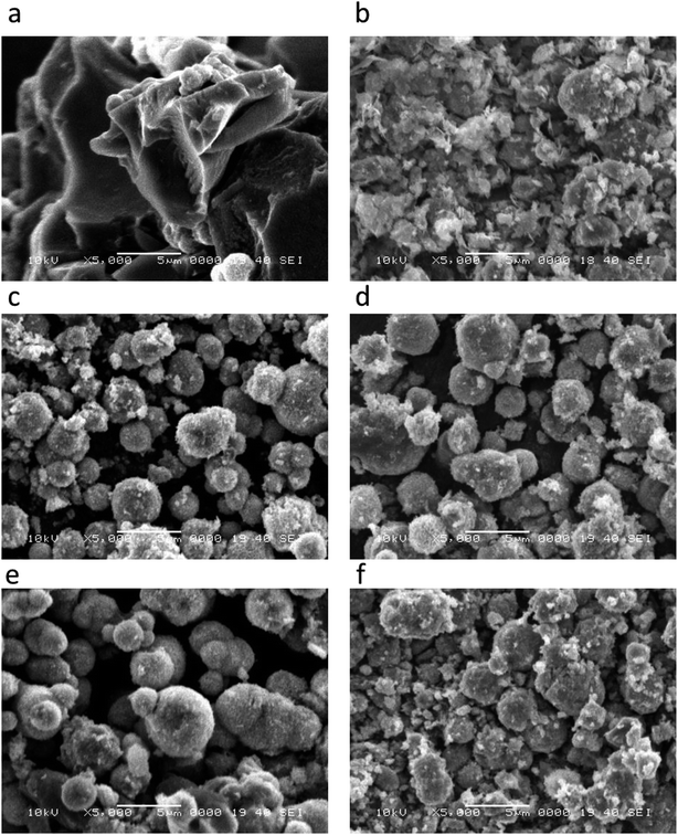
The morphological features of pristine NiO and carbon materials were investigated by scanning electron microscopy (SEM) as shown in Fig. 1. A low magnification image of as obtained carbon is shown in Fig. 1(a), which indicates that carbon exhibits nanoskeleton structure. However, the pristine NiO prior to the deposition on carbon is a mixture of porous and spherical particles shape as shown in Fig. 1(b). After the deposition of NiO on nanoskeleton carbon, the ball shape-oriented nanoparticles show negligible alteration on various contents of carbon as shown in Fig. 1(c and d). This indicates that the variation of carbon content does not bring any considerable change in the shape orientation of NiO nanostructures. The crystalline structure, composition and phase purity of as obtained crystals of NiO, carbon and NiO/C composite catalysts were evaluated by X-ray diffraction (XRD) technique. The XRD patterns for the pristine NiO and its composite with various carbon content are shown in Fig. 2. The XRD patterns shown in Fig. 2(a) corresponds to the pristine NiO and for samples 1, 2, 3, and 4 are depicted in Fig. 2(b–e) respectively. All the samples exhibited cubic phase and no any other impurity was found. All the diffraction patterns are purely coming from the NiO nanomaterial and well matched to the standard JCPDS card no. 96-101-0096. However, the carbon material has shown a broad reflection peak close to 25 theta degree which clearly indicates its poor crystalline features, as shown in S1.† Beside the NiO diffraction patterns few of the weak reflections for α-Ni (OH)2 are also found and they are in good agreement with the standard JCPDS card no. (JCPDS 22-0444).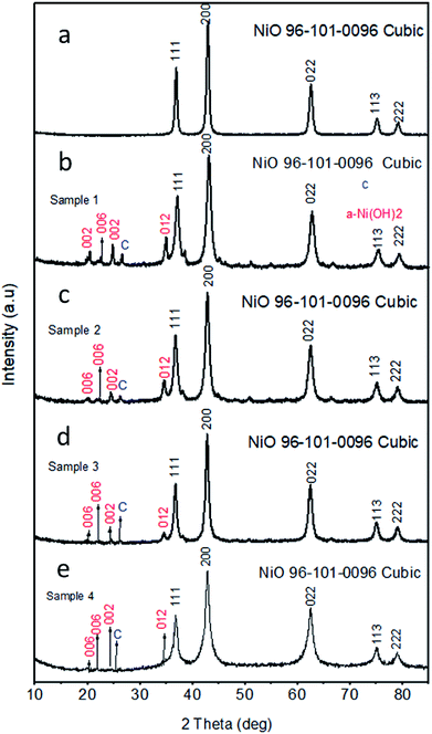 | ||
| Fig. 2 XRD spectra for various catalysts (a) pristine NiO, (b) sample 1, (c) sample 2, (d) sample 3, (e) sample 4 NiO/C composites respectively. | ||
Fig. 3 shows the chemical bonding features of NiO with various content of carbon, pristine nanoparticles NiO and carbon itself by the Fourier transform IR (FTIR) technique. The bands at 2347 cm−1 are mainly coming from the CO2 as the sample for FTIR measurement was prepared under normal atmospheric conditions. The bands at 1640 cm−1 of pure NiO are assigned to the vibration of the C![[double bond, length as m-dash]](https://www.rsc.org/images/entities/char_e001.gif) C. The characteristic Ni–O chemical bond is found between 477 to 681 cm−1, however in this study we found two shoulder peaks at 615 and 681 cm−1 which are assigned to Ni–O stretching vibration. All the band shifts in frequency values reveals a strong interaction between carbon and NiO materials.28,29
C. The characteristic Ni–O chemical bond is found between 477 to 681 cm−1, however in this study we found two shoulder peaks at 615 and 681 cm−1 which are assigned to Ni–O stretching vibration. All the band shifts in frequency values reveals a strong interaction between carbon and NiO materials.28,29
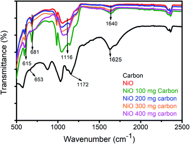 | ||
| Fig. 3 FTIR study of pure carbon, pristine NiO, NiO 100 mg carbon, NiO 200 mg carbon, NiO 300 mg carbon, NiO 400 mg carbon. | ||
The chemical composition of the prepared composite materials was also evaluated by energy dispersive spectroscopy (EDS) and it has confirmed the presence of carbon, Ni and O as main elements which strongly supports the FTIR and XRD analysis. The EDS spectra are shown in S2.†
3.2. Oxygen evolution reaction activity of NiO/C composite
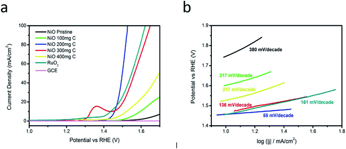
Linear sweep voltammetry (LSV) was used to evaluate the electrocatalytic activity of NiO/C composite in 1 M KOH. Fig. 4 shows the polarization curves of RuO2, bare glassy carbon electrode, pristine carbon, pure NiO, and NiO/C composites with different carbon contents at the scan rate of 5 mV s−1. All the potentials are reported with respect to a reversible hydrogen electrode (RHE). A negligible catalytic activity is reported for the GCE.It is obvious that NiO/C composites with different carbon content have shown an enhanced OER activity compared to the pristine NiO and carbon. The composite samples show higher OER activity, possibly due to the increased surface area of composite material and increased conductivity due to carbon material. Fig. 4(a) shows that NiO/C composite sample 2 with 200 mg C can produce current densities of 10 and 20 mA cm−2 at an applied potential of 1.45 and 1.47 V vs. RHE, respectively, showing the highest current values. The samples 3 and 4 are also very active for OER compared to the pristine carbon and NiO. This could be attributed to high content of carbon in sample 3 and 4 that has high density of active sites, thus the optimized condition for getting the best OER activity is herein reported for the sample 2. In case of sample 3, the anodic peak at 1.36 V might be attributed to Ni2+ to Ni3+ oxidation process and at 1.45 V is related to water oxidation and the obtained results are consistent with the reported work.30 Generally, the pre-oxidation is assigned to the M2+ (M–OH; here M is = Ni) to M3+ (M–OOH) oxidation and notice to be in the range of 1.25 to 1.43 V vs. RHE as in case of sample 3 we found peroxidation peak. We found a little peroxidation peak in RuO2 as shown in Fig. 4(a), however in other samples no peroxidation was seen. It is found that the peroxidation peaks are very much close to the OER activity. The height of current or the integrated peak area related to pre-oxidation peak corresponds to the density of active sites (M-OOH) on the surface of metal oxide and consequently it favors the OER activity of an electrocatalyst. There is a strong relationship between the peroxidation peak and the composition of an electrocatalyst.31–33
The samples 1, 3 and 4 require more bias voltage to produce a current density of 10 mA cm−2. The electrocatalytic performance of composite sample 2 with 200 mg C was compared with noble metal oxide catalyst RuO2. The comparison indicates that RuO2 can produce a current density of 20 mA cm−2 at higher applied potential vs. RHE compared to sample 2 as shown in Fig. 4(a), which also demonstrates that the prepared NiO/C (sample 2) is highly active for OER and requires lower potential than RuO2. The OER kinetics was also investigated via Tafel slope value. It has been shown that the OER mechanism is not fully understood, but generally OER mechanism on the transition metal oxides was stated by Y. Li et al.34 in alkaline media as shown in the following chemical equations:
| M* + OH− → M*OH + e− | (a) |
| M*OH + OH− → M*O + H2O + e− | (b) |
| M*O + OH− → M*OOH + e− | (c) |
| M*OOH + OH− → M*O2 + H2O + e− | (d) |
| M*O2 → M* + O2 | (e) |
The Volmer reaction, Heyrovsky reaction, and Tafel reaction are corresponded to the Tafel slope values of 120, 40, and 30 mV dec−1 respectively.35–37
For a better understanding of excellent OER activity of NiO/C based composite catalysts (samples 1, 2, 3 and 4) and pristine NiO, the Tafel slopes were measured from OER polarization curves. Fig. 4(b) shows that NiO/C composite electrocatalyst (sample 2) has a Tafel slope value of 55 mV per decade, which is lower than the pristine NiO, and NiO/C composite electrocatalysts (samples 1, 3, and 4). The governing OER mechanism for the sample 2 is the Volmer–Heyrovsky reaction mechanism. The Tafel slope reflects the rate of change of the current density with the overpotential.38–40 A low value of Tafel slope means, a small increase in the overpotential leads to significant increase of the obtained current density. The lowest Tafel slope value was obtained for composite sample 2 with 200 mg C, which is comparable to the recently published works,38–40 that indicates excellent OER activity due to the synergetic effect produced between the carbon and NiO during the synthesis process.
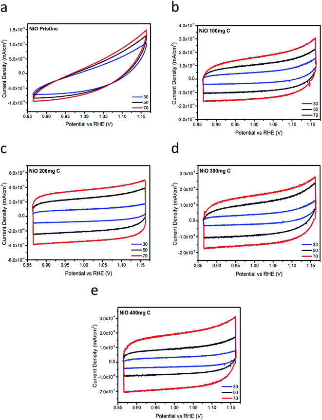
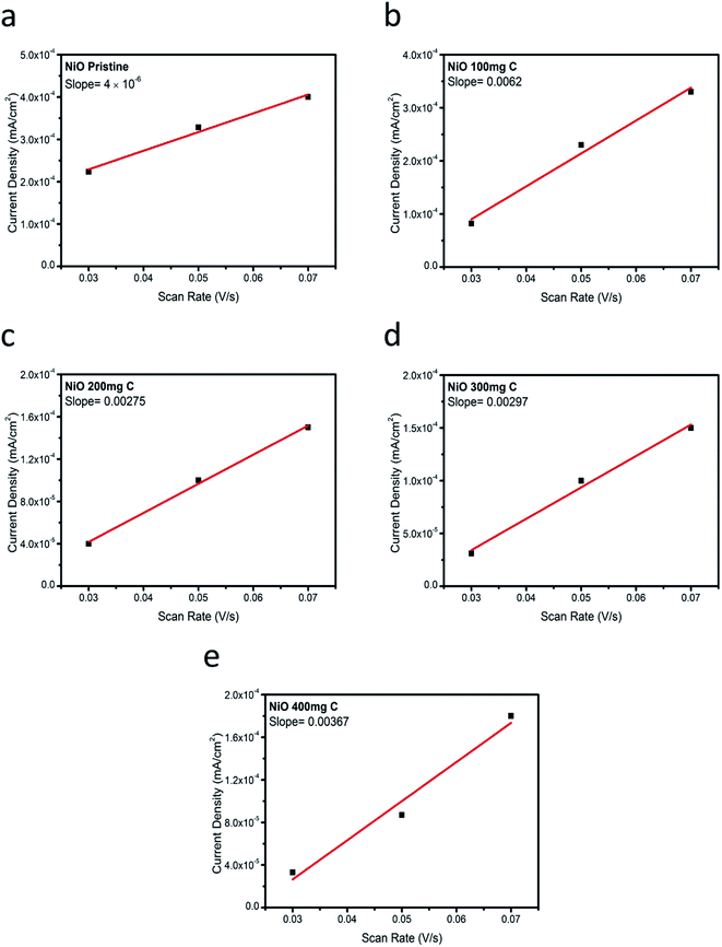
To further investigate the superior performance of the prepared electrocatalysts of NiO with carbon, the double layer capacitance (Cdl) regarding the several samples was determined by measuring the non-faradaic capacitive current associated with double-layer charging in the non-faradic region from the scan-rate dependence of cyclic voltammograms. All the measured current in the non-faradaic potential region is assumed to be due to double-layer charging.23–25 The electrochemically active surface area (ECSA) is generally assumed to be proportional to the double layer capacitance,41 and therefore, the information on the Cdl is relevant for the characterization of OER activity. Fig. 5 shows the cyclic voltammetry (CV) curves at various scan rates in 1 M KOH. From the cyclic voltammetry curves, double layer charging current is estimated at a potential of 0.05 V and plotted vs. different scan rates. After the linear fitting, the value of the slope corresponds to the Cdl (double layer capacitance). The values for the Cdl for the pristine NiO and carbon, NiO/C composite (samples 1, 2, 3 and 4) are shown in Fig. 6. The estimated Cdl values of pure carbon, pristine NiO, sample 1, sample 2, sample 3, and sample 4 are 1.7 × 10⁻⁴, 4 × 10⁻⁶, 6.2 × 10⁻³, 2.9 × 10⁻³, and 3.6 × 10⁻³ F cm−2, respectively. The highest value of the Cdl (6.2 × 10⁻³ F cm−2) for the composite sample 2 with 200 mg C agrees with the robust OER activity. The excellent electrocatalytic activity could be assigned to the great surface provided by the carbon material for the deposition of NiO nanostructure which has further improved their catalytic properties. Further, it supports the charge transfer and provides easy path to the electrolyte to penetrate within the structure of NiO/C composite which further easily meet the active edges of composite electrocatalysts.
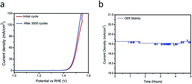
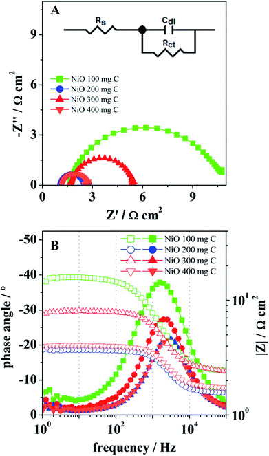
Fig. 7(a) show the stability experiments for the sample 2 obtained through various cyclic voltammetry runs at 5 mV s−1. Electrocatalyst has high capability to retain its activity for a long time, thus it is suggested that the NiO/C composite sample (sample 2) can be used for large-scale applications. A chronoamperometric experiment was performed at 1.45 V vs. RHE for 5 h (Fig. 7(b)) revealed a significant stability and further it ensures the capability of the electrocatalyst for practical applications. The kinetics of oxygen evolution reaction (OER) at the NiO/C composite electrodes was also investigated by electrochemical impedance spectroscopy (EIS). Fig. 8 presents the Nyquist (A) and Bode (B) plots for the OER at the electrocatalysts at room temperature and under an applied potential of 1.45 V vs. RHE. All the samples showed only a well resolved semicircle in the Nyquist plots, as well as a single peak in the Bode plots, with the corresponding relaxation being assigned to the charge transfer process. The inset in (A) shows a one time-constant equivalent circuit used to interpret the impedance data, in which Rs is the ohmic resistance of the solution, Rct is the charge transfer resistance, related to the overall rate of the OER, and Cdl the double layer capacitance.41–43 After fitting the impedance data, the parameters Rct and Cdl were obtained, as presented in Table 1.
| Rs/Ω cm2 | Rct/Ω cm2 | Cdl/F cm−2 | |
|---|---|---|---|
| NiO 100 mg carbon | 2.7 | 11.5 | 2.1 × 10⁻⁵ |
| NiO 200 mg carbon | 1.6 | 2.0 | 4.5 × 10⁻⁵ |
| NiO 300 mg carbon | 2.7 | 5.0 | 2.6 × 10⁻⁵ |
| NiO 400 mg carbon | 1.8 | 2.2 | 4.5 × 10⁻⁵ |
The charge transfer resistance, Rct, showed a remarkable decrease form the sample containing 100 mg of C to that with 200 mg of C, with this one presenting a value of 2 Ω cm2, the lowest charge transfer resistance among all the composite samples. Increasing the C content to 300 mg lead to increased charge transfer resistance, and then again to a lower value for the 400 mg C sample. Regarding the double layer capacitance, Cdl, values of the order of 10−5 F cm−2 were obtained, inside the range generally obtained for the double layer capacitance.5–47 The increase of the carbon content on Cdl reveals a similar (inverse) effect to that on the charge transfer resistance. The samples with 200 and 400 mg C showed the highest capacitance value of 4.5 × 10⁻⁵, whereas the samples with 100 and 300 mg C showed lower values of 2.1 × 10⁻⁵ and 2.6 × 10⁻⁵ F cm−2, respectively. Ii is worth noting that the determination of Cdl by EIS also lead to a highest value in the case of sample 2, as obtained before using the non-faradaic current. The EIS observations suggest that the increase on the carbon content systematically leads to the decrease of the charge transfer resistance and the increase of the double layer capacitance, but with the best values being obtained for 200 mg C on the material composition (sample 2), which seems to be in agreement with the higher catalytic activity of this sample towards the OER, as discussed above. The performance of sample 2 electrocatalyst in terms of Tafel slope and an over potential to achieve a current density of 10 mA cm−2 is compared with the recently reported Ni-based electrocatalysts in alkaline media48–55 as given in S1 Table.† It is obvious from the S1 Table† that the proposed electrocatalyst is more efficient and can be integrated into practical water splitting devices due to low over potential.
4. Conclusions
We have developed a simple strategy to prepare NiO/C based composites with the carbon material that is obtained by simple dehydration of sucrose sugar. The NiO nanostructures are decorated on carbon through wet chemical method. These composite electrocatalysts have shown an excellent electrocatalytic activity towards OER. To best of our knowledge and available literature, there is no report about the use of carbon material obtained from the dehydration of sucrose sugar and combined with NiO nanostructures. The sample 2 with 200 mg C can produce a current density of 10 mA cm−2 at the bias potential of 1.45 V vs. RHE only which is the lowest possible potential to date. The Tafel slope of 55 mV dec−1 is the lowest for NiO based catalysts to date. The NiO/C composite material also exhibits good stability during the OER process. Electrochemical impedance spectroscopy experiments confirm the best performance of the NiO/C composite with 200 mg C, with this material revealing the lowest charge transfer resistance and the highest double layer capacitance, which may be associated with higher electrochemically active surface area. The presence of carbon in NiO composite results in a swift charge transfer and consequently leading a robust catalytic activity towards OER. The findings indicate that the composite has superior electrochemical properties, therefore, it can be capitalized for a wide range of energy storage applications such as water splitting devices, supercapacitors, lithium-ion batteries, and fuel cells.Conflicts of interest
Authors declare no conflict of interest in this research work.Acknowledgements
L. Amaral would like to thank Fundação para a Ciência e Tecnologia (FCT, Portugal) for postdoctoral research grant SFRH/BPD/97453/2013.References
- H. Wang and X. Zhang, Sci. China Mater., 2016, 59, 521–522 CrossRef CAS.
- M. R. Gao, Y.-F. Xu, J. Jiang and S.-H. Yu, Chem. Soc. Rev., 2013, 42, 2986–3017 RSC.
- M. G. Walter, E. L. Warren, J. R. McKone, S. W. Boettcher, Q. Mi, E. A. Santori and N. S. Lewis, Chem. Rev., 2010, 110, 6446 CrossRef CAS PubMed.
- Y. Li and C. Zhao, Chem. Mater., 2016, 28, 5659 CrossRef CAS.
- J. Wang, W. Cui, Q. Liu, Z. Xing, A. M. Asiri and X. Sun, Adv. Mater., 2016, 28, 215 CrossRef CAS PubMed.
- G. Lewandowicz, T. Jankowski and J. Fornal, Carbohydr. Polym., 2000, 42, 193–199 CrossRef CAS.
- I. Roger and M. D. Symes, J. Mater. Chem. A, 2016, 4, 6724 RSC.
- M. I. Jamesh, J. Power Sources, 2016, 333, 213 CrossRef CAS.
- H. Osgood, S. V. Devaguptapu, H. Xu, J. Cho and G. Wu, Nano Today, 2016, 11, 601 CrossRef CAS.
- T. J. Meyer, Nature, 2008, 451, 778–779 CrossRef CAS PubMed.
- C. Bocca, A. Barbucci, M. Delucchi and G. Cerisola, Int. J. Hydrogen Energy, 1999, 24, 21–26 CrossRef CAS.
- L. Trotochaud, J. K. Ranney, K. N. Williams and S. W. Boettcher, J. Am. Chem. Soc., 2012, 134, 17253–17261 CrossRef CAS PubMed.
- R. L. Doyle and M. E. G. Lyons, Phys. Chem. Chem. Phys., 2013, 15, 5224–5237 RSC.
- D. Cibrev, M. Jankulovska, T. Lana-Villarreal and R. Gomez, Int. J. Hydrogen Energy, 2013, 38, 2746–2753 CrossRef CAS.
- R. L. Doyle and M. E. G. Lyons, J. Electrochem. Soc., 2013, 160, H142–H154 CrossRef CAS.
- F. Cheng, J. Shen, B. Peng, Y. Pan, Z. Tao and J. Chen, Nat. Chem., 2011, 3, 79–84 CrossRef CAS PubMed.
- K. J. May, C. E. Carlton, K. A. Stoerzinger, M. Risch, J. Suntivich, Y. L. Lee, A. Grimaud and Y. S. Horn, J. Phys. Chem. Lett., 2012, 3, 3264–3270 CrossRef CAS.
- S. Raabe, D. Mierwaldt, J. Ciston, M. Uijttewaal, H. Stein, J. Hoffmann, Y. M. Zhu, P. Blochl and C. Jooss, Adv. Funct. Mater., 2012, 22, 3378–3388 CrossRef CAS.
- A. Grimaud, K. J. May, C. E. Carlton, Y.-L. Lee, M. Risch, W. T. Hong, J. Zhou and Y. S. Horn, Nat. Commun., 2013, 4, 2439 CrossRef PubMed.
- S. A. Mohammad, C. Byungchul and B. K. Young, Sci. Rep., 2018, 8, 2543 CrossRef PubMed.
- Z. Yufei, C. Shuangqiang, S. Bing, S. Dawei, H. Xiaodan, L. Hao, Y. Yiming, S. Kening and W. Guoxiu Wang, Sci. Rep., 2015, 23, 7629 Search PubMed.
- L. Ziyang, W. Jing, H. Shifei, H. Yanglong, L. Yanguang, Z. Yueping, M. Shichun, Z. Jiujun and Z. Yufeng, Nano Energy, 2017, 42, 334–340 CrossRef.
- A. M. Lukowski, S. D. Andrew, M. Fei, F. Audrey, L. Linsen and J. Song, J. Am. Chem. Soc., 2013, 135, 10274 CrossRef PubMed.
- W. Sheng, A. G. Hubert and Y. S. Horn, J. Electrochem. Soc., 2010, 157, B1529 CrossRef CAS.
- X. Lu and C. Zhao, Nat. Commun., 2015, 6, 6616 CrossRef CAS PubMed.
- C. L. C. McCrory, S. Jung, J. C. Peters and T. F. Jaramillo, J. Am. Chem. Soc., 2013, 135, 16977–16987 CrossRef CAS PubMed.
- X. Xiang, F. Song and X. Hu, Nat. Commun., 2016, 7, 12324 CrossRef CAS PubMed; J. Zhu, Z. Lu, S. T. Aruna, S. T. D. Aurbach and A. Gedanken, Chem. Mater., 2000, 12, 2557–2566 CrossRef.
- Z. Hu, L. Zu, Y. Jiang, H. Lian, Y. Liu, X. Wang and X. Cui, Polym. Compos., 2015, 1616 Search PubMed.
- C. Zhu, D. Wen, S. Leubner, M. Oschatz, W. Liu, M. Holzschuh, F. Simon, S. Kaskel and S. Eychmüller, Chem. Commun., 2015, 51, 7851 RSC.
- J. Masa, P. Weide, D. Peeters, I. Sinev, W. Xia, Z. Sun, C. Somsen, M. Muhler and W. Schuhmann, Adv. Energy Mater., 2016, 6, 1502313 CrossRef.
- B. S. Yeo and A. T. Bell, J. Phys. Chem. C, 2012, 116, 8394 CrossRef CAS.
- L. Trotochaud, J. K. Ranney, K. N. Williams and S. W. Boettcher, J. Am. Chem. Soc., 2012, 134, 17253 CrossRef CAS PubMed.
- M. W. Louie and A. T. Bell, J. Am. Chem. Soc., 2013, 135, 12329 CrossRef CAS PubMed.
- Y. Li, H. X. Li, K. Z. Cao, T. Jin, X. J. Wang, H. M. Sun, J. X. Ning, Y. J. Wang and L. F. Jiao, Energy Storage Mater., 2018, 12, 44 CrossRef.
- H. Su, H. H. Wang, B. Zhang, K. X. Wang, X. H. Lin and J. S. Chen, Nano Energy, 2016, 22, 79 CrossRef CAS.
- H. Y. Jin, J. Wang, D. F. Su, Z. Z. Wei, Z. F. Pang and Y. Wang, J. Am. Chem. Soc., 2015, 137, 2688 CrossRef CAS PubMed.
- M. Gong, W. Zhou, M. C. Tsai, J. Zhou, M. Guan, M. C. Lin, B. Zhang, Y. Hu, D. Y. Wang, J. Yang, S. J. Pennycook, B. J. Hwang and H. J. Dai, Nat. Commun., 2014, 5, 4695 CrossRef CAS PubMed.
- C. S. Lim, C. K. Chua, Z. Sofer, K. Klimova, C. Boothroyd and M. J. Pumera, J. Mater. Chem. A, 2015, 3, 11920 RSC.
- Y. Qiu, L. Xin and W. Li, Langmuir, 2014, 30, 7893 CrossRef CAS PubMed.
- D. Wang, F. Watanabe and W. Zhao, ECS J. Solid State Sci. Technol., 2017, 6, 3049–3054 CrossRef.
- Y. Y. Chen, Y. Zhang, W. J. Jiang, X. Zhang, Z. Dai, L. J. Wan and J. S. Hu, ACS Nano, 2016, 10, 8851–8860 CrossRef CAS PubMed.
- J. R. Swierk, et al., J. Phys. Chem. C, 2015, 119, 19022–19029 CrossRef CAS.
- R. L. Doyle and M. E. G. Lyons, Phys. Chem. Chem. Phys., 2013, 15, 5224–5237 RSC.
- J. Milikić, M. Vasić, L. Amaral, Ni. Cvjetićanin, D. Jugović, R. Hercigonja and B. Šljukić, Int. J. Hydrogen Energy, 2018, 18977 CrossRef.
- L. Amaral, D. S. P. Cardoso, B. Šljukić, D. M. F. Santos and C. A. C. Sequeira, J. Electrochem. Soc., 2017, 164, F427–F432 CrossRef CAS.
- M. Vasić, M. Čebela, I. Pašti, L. Amaral, R. Hercigonja, D. M. F. Santos and B. Šljukić, Electrochim. Acta, 2018, 259, 882–892 CrossRef.
- L. Amaral, J. Minkiewicz, B. Š. Paunkovic, D. M. F. Santos, C. A. C. Sequeira, M. Vraneš and S. Gadžurić, ACS Appl. Energy Mater., 2018, 1, 4731–4742 CrossRef CAS.
- C. Zhu, D. Wen, S. Leubner, M. Oschatz, W. Liu, M. Holzschuh, F. Simon, S. Kaskel and A. Eychmüller, Chem. Commun., 2015, 51, 7851 RSC.
- H. Cheng, Y. Z. Su, P. Y. Kuang, G. F. Chen and Z. Q. Liu, J. Mater. Chem. A, 2015, 3, 19314–19321 RSC.
- K. L. Yan, X. Shang, Z. Li, B. Dong, X. Li, W. K. Gao, J. Q. Chi, Y. M. Chai and C. G. Liu, Appl. Surf. Sci., 2017, 416, 371–378 CrossRef CAS.
- E. Umeshbabu and G. R. Rao, Electrochim. Acta, 2016, 213, 717–729 CrossRef CAS.
- W. Y. Xia, N. Li, Q. Y. Li, K. H. Ye and C. W. J. Beenakker, Sci. Rep., 2016, 623398 Search PubMed.
- Y. Xiao, L. Feng, C. Hu, V. Fateev, C. Liu and W. Xing, RSC Adv., 2015, 5, 61900–61905 RSC.
- X. Lv, Y. Zhu, H. Jiang, X. Yang, Y. Liu, Y. Su, J. Huang, y. Yao and C. Li, Dalton Trans., 2015, 44, 4148–4154 RSC.
- M. Chavi and B. Mrinmoyee, ACS Omega, 2017, 11, 7559–7567 Search PubMed.
Footnote |
| † Electronic supplementary information (ESI) available. See DOI: 10.1039/c8ra10472g |
| This journal is © The Royal Society of Chemistry 2019 |

