 Open Access Article
Creative Commons Attribution 3.0 Unported Licence
Control of the dual emission from a thermally activated delayed fluorescence emitter containing phenothiazine units in organic light-emitting diodes†
Ikbal Marghad ab,
Fatima Bencheikhac,
Chao Wang
 d,
Sophia Manolikakesb,
Alice Rératb,
Corinne Gosminib,
Dae hyeon Kimac,
Jean-Charles Ribierre*ac and
Chihaya Adachi
 *ac
*ac
aCenter for Organic Photonics and Electronics Research (OPERA), Kyushu University, Motooka 744, Nishi, Fukuoka 819-0395, Japan. E-mail: ribierre@opera.kyushu-u.ac.jp; adachi@opera.kyushu-u.ac.jp
bLaboratoire de chimie moléculaire LCM, Ecole Polytechnique, CNRS, 91128 Palaiseau Cedex, France
cJapan Science and Technology Agency (JST), ERATO, Adachi Molecular Exciton Engineering Project, Fukuoka 819-0395, Japan
dDepartment of Polymer Science and Engineering, Zhejiang University, Hangzhou 310027, China
First published on 4th February 2019
Abstract
The development of single-component organic dual light-emitting molecules is of interest for a range of applications including white organic light-emitting diodes. Herein, a new thermally-activated delayed fluorescent molecule containing 4,6-bis-phenyl phenothiazine as donor units and 2-thiophene-1,3,5-triazine as acceptor unit was synthesized using a simple cost-effective method. This compound shows two stable molecular conformations due to the presence of the phenothiazine units in its molecular structure. These conformers exhibit different photophysical properties in both solution and thin films. The electroluminescence properties of this novel emitter were then examined in organic light-emitting diodes and the results provide useful insights into the influence of the device architecture on the dual emission characteristics. The experimental results were consistent with the optical simulations and the optimized architecture led to the fabrication of electroluminescent devices with an external quantum efficiency of 11.5% and a maximum luminance value of 10![[thin space (1/6-em)]](https://www.rsc.org/images/entities/char_2009.gif) 370 cd m−2.
370 cd m−2.
Introduction
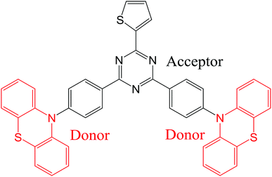
Organic light-emitting diodes (OLEDs) are now used in commercially available display applications and are extremely promising for solid-state lighting sources. Since the demonstration of fluorescent OLED in 1987 by Tang and VanSlyke,1 great enhancement of the electroluminescence (EL) quantum efficiency has been achieved using phosphorescence,2–4 triplet fusion5,6 and thermally-activated delayed fluorescence (TADF).7–15 In particular, light-emitting molecules with TADF properties are considered now as the third generation of OLED materials and enable the harvesting of light from both singlet and triplet excitons without the use of any noble heavy metals. A large number of studies has already reported high-performance OLEDs using blue, green, red and near infrared TADF emissive dopants.16–20 In most cases, to achieve such a high-efficiency TADF emission, a small singlet–triplet energy gap (ΔEST) is crucial to facilitate the upconversion from triplet to singlet excited states via thermally-activated reverse intersystem crossing (RISC) process. The most popular approach that have been used to develop TADF OLED emitters showing simultaneously small (ΔEST) and increased oscillator strength is based on twisted molecular donor–acceptor architectures with large dihedral angles between the electron-donating and accepting units, resulting in a small spatial overlap between the highest occupied molecular orbital (HOMO) and the lowest unoccupied molecular orbital (LUMO) frontier orbitals.21–25 Interestingly, among the large variety of TADF OLED emitters, some of them have been found to exhibit dual emission due to the existence of stable conformers.26–33 This class of TADF emitters is evidently of strong interest for white TADF OLEDs and could be promising for other imaging or sensing applications benefiting from a broad emission. Noticeably, while the first example of single-component dual TADF emission was obtained using dyes containing phenothiazine units,28 other moieties such as 9,9-dimethyl-9,10-dihydroacridine and phenoxazine have also been recently incorporated into light-emitting dyes with dual stable conformations leading to dual TADF emission during excitations.26,34 In this context, the development of innovative TADF molecular architectures with dual conformations for highly efficient OLEDs and a deeper understanding of this dual emission phenomenon are still required.In this study, we report on the synthesis of a novel TADF emitter ((T-TRZ)-PTZ) containing peripheral phenothiazine donor units and a central 2-thiophene-1,3,5-triazine acceptor unit using a cost-effective synthetic method. A schematic representation of the chemical structure of this dye is shown in Fig. 1. The 2-thiophene unit was herein chosen to shift the dual TADF emission toward longer wavelengths compared to the previously-reported phenyl analogue29 and to determine its potential influence on the electronic structure of the molecule.35,36 In this context, quantum chemistry calculations as well as the characterization of the photophysical and EL properties of this novel compound are expected to provide insights into the dual emission of TADF molecules containing phenothiazine units. In addition, optical simulations of the EL device properties are carried out to demonstrate the role played by the OLED architecture on the dual emission properties.
Results and discussion
Synthesis of (T-TRZ)-PTZ
Most of the reaction steps for the synthesis of emitters based on 1,3,5-triazine use expensive catalysts such as palladium. Recently, we reported for the first time a cost-effective and simple synthetic method for the synthesis of TADF emitters incorporating 1,3,5-triazine moieties, which is based on the cobalt catalysed cross coupling of arylzinc with aryl halide.29 The important benefit from this approach is related to its production cost which is lower than using palladium catalyst. In the present work, we used this cobalt catalysed cross coupling method for the synthesis of (T-TRZ)-PTZ 3. The synthetic route is based on three main steps as described in Scheme 1. In first place, the mono-substitution reaction of the 1,3,5-triazine with the thiophen-2-ylzinc(II) bromide catalysed by the cobalt cross-coupling was performed leading to the mono-thiophene triazine intermediate 1 containing two chloro functions that can be further substituted. This first step is then followed by another cobalt cross-coupling between the triazine intermediate 1 and the 4-fluorophenylzinc(II) bromide, previously prepared from commercially available 4-bromofluorobenzene. This last coupling leads to the triazine intermediate 2 presenting two fluoro functions. The final product 3 was then obtained from 2 by a simple nucleophilic aromatic substitution of phenothiazine in presence of a strong base such as sodium hydride. Detailed chemical characterization of the intermediates and final product, including NMR and HRMS, is provided in ESI (Fig. S1–S4†).Quantum chemistry calculations
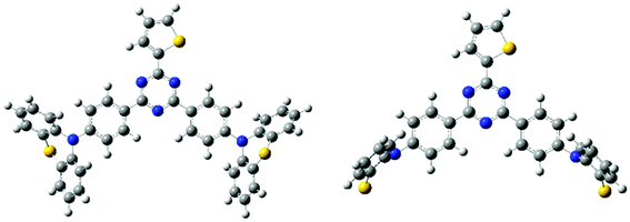
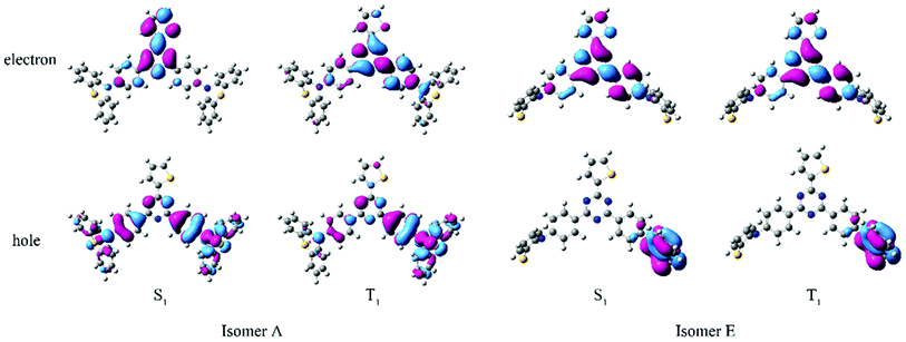
All the quantum chemistry calculations were performed using Gaussian 09.37 The electronic structures of (T-TRZ)-PTZ were examined using density functional theory (DFT) and time-dependent density functional theory (TDDFT) with the Tamm–Dancoff approximation (TDA)38 for avoiding triplet instabilities.39 The ground-state geometries of (T-TRZ)-PTZ were optimized at the B3LYP/6-31G* level. Because of the presence of two phenothiazine units in ((T-TRZ)-PTZ), different stable conformations can be expected for this molecule. As shown in Fig. 2 and Table S1,† one axial (conformer A) and one equatorial (conformer E) configurations are evidenced by the calculations and are found to show minor energy differences (Table S2†). Fig. 3 shows the distribution of the hole and electron natural transition orbitals (NTOs) of S1 and T1 calculated at the B3LYP/6-31G(d) level of theory based on the S0 geometry for both conformers A and E using Multiwfn 3.4.40For each conformer, it is interesting to note that the donor moieties dominate the hole NTOs while the acceptor moieties determine the electron NTOs. Compared to conformer A, the almost identical hole and electron NTOs for the S0 → S1 and S0 → T1 charge transfer (CT) transitions in conformer E suggest a vanishing ΔEST.41 Thus a more facile exciton transformation channel via ISC and RISC may process between S1 and T1. As shown in Table S3,† the two conformers are expected to exhibit different photophysical properties. For instance, calculations indicate that the conformer A should exhibit a strong absorption peak at about 378 nm (3.28 eV) while conformer E should display a flatter and broad absorption band around 532 nm (2.33 eV). The theoretical results also confirm that (T-TRZ)-PTZ should exhibit a dual emission as a direct consequence of the presence of two phenothiazine units in its molecular structure. Importantly, the theoretical results show that the calculated ΔEST values of the conformers A and E in their optimized ground-state geometries are 0.46 eV and 0.01 eV, respectively. This suggests that TADF activity should be significantly more effective in the conformer E. Interestingly, these ΔEST values are slightly different from those calculated in the previously-reported phenyl analogue29 (0.0079 and 0.71 eV for the E and A conformers, respectively).
Photophysical properties of (T-TRZ)-PTZ
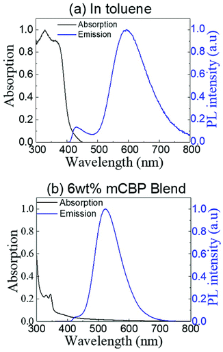
The absorption and steady-state photoluminescence (PL) spectra of (T-TRZ)-PTZ measured at room temperature in degassed toluene solution are displayed in Fig. 4a. Concentration of the solution was 1 × 10⁻⁵ M. The dye (T-TRZ)-PTZ exhibits two main intense absorption bands at 330 and 364 nm, which are assigned to the 1(π,π*) ← S0 transition of the 1,3,5 triazine. In addition, the weak absorption tail at wavelengths longer than 400 nm is related to the intramolecular CT character of the quasi-equatorial conformer of the molecule. The steady-state PL spectrum of (T-TRZ)-PTZ in toluene shows a dual emission with two peaks at around 430 and 593 nm, respectively. The peak at 593 nm shows the highest intensity, a large Stokes shift and a full-width-at-half-maximum of 96 nm, which can be assigned to the emission from the singlet excited state of the quasi-equatorial conformation. The peak at 430 nm presents a significantly lower PL intensity and is attributed to the emission from the singlet excited state of the quasi-axial conformer. Noticeably, the PL emission of (T-TRZ)-PTZ in toluene is about 18 nm red-shifted compared to that of the previously-reported phenyl analogue.29 The results indicate that the incorporation of the thiophene unit in (T-TRZ)-PTZ affects the singlet–triplet gap as evidenced by the quantum chemistry calculations and the steady-state PL emission of the molecule.Fig. 4b shows the absorption and steady-state PL spectra of (T-TRZ)-PTZ doping at 6 wt% a 3,3′-bis(N-carbazolyl)-1,1′-biphenyl (mCBP) host. The film was thermally evaporated on top of a fused silica substrate. The mCBP host was selected due to its high triplet energy T1, which prevents back energy transfer from the guest to the host molecules and confines the triplets within the guest emitters. Because of the small doping concentration of the guest molecules, the absorption spectrum of the mCBP blend is strongly dominated by the absorption of the host molecules. In particular, the absorption bands observed at 330 and 344 nm are due to the presence of carbazole units in the mCBP molecule.42 Noticeably, considering the excitation wavelength of 340 nm, the steady-state PL spectrum of the mCBP blend does not show any emission from the host. This implies that an efficient energy transfer takes place from the mCBP host to the (T-TRZ)-PTZ doping molecules.43–45 It can also be seen that the steady-state PL spectrum of the blend film exhibits a dual emission with two peaks located around 423 and 523 nm, respectively. Similarly to the solution case, the low and high energy peaks are attributed to the quasi-equatorial and quasi-axial conformers, respectively. It is worth noting that the emission peak of the quasi-equatorial conformer is significantly blue-shifted in the blend, as compared to its PL spectrum in toluene. This is presumably due to the ICT character of (T-TRZ)-PTZ and the different polarity of the environment.11,20,46,47
To gain further insights into the photophysics of (T-TRZ)-PTZ, the transient PL decay of the equatorial conformer was measured in degased and non-degased toluene solution at a low concentration around 10−6 M. Excitation wavelength was 337 nm and the emission wavelength was 593 nm. The kinetics shown in Fig. 5 can be described by the sum of two exponential decay functions. We define the slow and fast time constants characteristics of these exponential decay functions to the delayed and prompt fluorescence lifetimes, respectively. While the prompt fluorescence lifetime does not change with the presence or not of oxygen and is in the order of 10 ns, the delayed fluorescence lifetime is found to increase from 50 ns to 570 ns after degasing the toluene solution. These data indicate that the equatorial conformer of (T-TRZ)-PTZ shows some TADF properties, in accordance with the theoretical results obtained by quantum chemistry calculations. The observed behavior in presence of oxygen shows indeed that the triplet states involved in the TADF process are readily quenched by the oxygen triplet ground state and this fully supports the assignment of TADF. An important parameter which needs to be measured in order to evaluate the potential of (T-TRZ)-PTZ for OLEDs is its photoluminescence quantum yield (PLQY) in thin film. We found that the PLQY of the 6 wt% mCBP blend in nitrogen atmosphere yields a value of 43%.
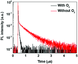 | ||
| Fig. 5 Transient fluorescence decays of (T-TRZ)-PTZ in degased and non-degased toluene solutions. Excitation wavelength was 337 nm and emission wavelength was 593 nm. | ||
Characterization of the OLEDs
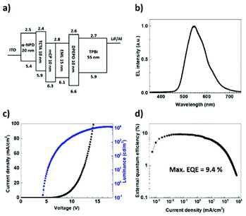
To examine the EL properties of (T-TRZ)-PTZ, the first batch of OLEDs had the following architecture: indium tin oxide (ITO) (100 nm)/N,N′-diphenyl-N,N′-bis(1-naphthyl)-1,10-biphenyl-4,4′-diamine (α-NPD) (20 nm)/tris(4-carbazoyl-9-ylphenyl)amine (TCTA) (10 nm)/1,3-bis(N-carbazoyl)benzene (mCP) (10 nm)/6 wt% (T-TRZ)-PTZ: mCBP (15 nm)/bis[2-(diphenylphosphino)phenyl]ether oxide (DPEPO) (10 nm)/1,3,5-tris(2-N-phenylbenzimidazolyl)benzene (TPBi) (55 nm)/lithium fluoride (LiF) (0.8 nm)/aluminium (Al) (900 nm). A schematic representation and energy diagram of the device structure are provided in Fig. 6a. α-NPD and mCP were chosen for the hole transport layers while DPEPO and TPBi were selected for the hole blocking and electron transport layers, respectively. Fig. 6b–d show the EL characteristics of this OLED. The device exhibits green-yellowish emission with a turn-on voltage of 4.6 V, a maximum current efficiency of 35.47 cd A−1, a power efficiency of 11.1 lm W−1, a maximum luminance up to 10![[thin space (1/6-em)]](https://www.rsc.org/images/entities/char_2009.gif) 370 cd m−2 and a maximum EQE of 9.4% without any light outcoupling enhancement. These data could be reproduced in several devices. The obtained EQE value is significantly higher than the upper theoretical limit stated for conventional fluorescent OLEDs. We attribute this result to an efficient TADF process enabling the effective upconversion of the triplets to the singlets via RISC,7 which is in agreement with the quantum chemistry calculations and previous reports devoted to similar dyes.
370 cd m−2 and a maximum EQE of 9.4% without any light outcoupling enhancement. These data could be reproduced in several devices. The obtained EQE value is significantly higher than the upper theoretical limit stated for conventional fluorescent OLEDs. We attribute this result to an efficient TADF process enabling the effective upconversion of the triplets to the singlets via RISC,7 which is in agreement with the quantum chemistry calculations and previous reports devoted to similar dyes.
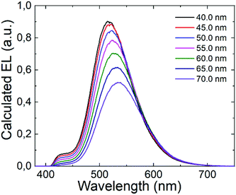
Looking at the EL spectra in Fig. 6b, it can be seen that only the emission from the quasi-equatorial conformer is observed. Previous reports have provided evidence of the strong influence of the OLED architecture on the EL spectra due to optical cavity effects.48–53 In order to examine the potential impact of these optical cavity effects on the dual emission spectrum of (T-TRZ)-PTZ, we carried out optical simulations to see if these optical cavity effects could hide the emission band at 427 nm. These optical simulations were performed using SETFOS 4.2 software in the wavelength range between 380 and 750 nm. The light-emitting process taking place in the emissive layer of the OLED is simulated based on the model of emissive dipoles embedded within a multilayer stack.54 Since the thicknesses of these layers are comparable to the wavelength of the emitted light, internal reflections at the different interfaces occur, leading to optical interference effects. To model these interference effects in the OLED, a transfer matrix method is used,55 taking into account the optical indices of the emissive layer determined by variable angle spectroscopic ellipsometry.56 It should be noted that the calculation was carried out by assuming randomly distributed transition dipole moment approximated by a Dirac distribution placed at the interface between the emissive layer and the mCBP one.
It is well established that the distance between the emitting zone and the metal cathode predominantly affects the interference conditions at the position of the emissive zone. In this context, we decided to vary the thickness of the TPBi layer in the (T-TRZ)-PTZ OLED and see how this affects the intensity of the band at 427 nm in the EL spectrum. Fig. 7 shows the calculated EL spectrum of the OLED for different thicknesses of the TPBi film (varying from 40 to 70 nm). The results demonstrate that the EL spectrum is red-shifted and the intensity of the band at 427 nm is decreased when the TPBi thickness increases. In other words, the fact that the emission peak at 427 nm was not observed in the EL spectrum can be explained by these interference effects. This clearly demonstrates that the architecture of the OLED should be carefully designed to optimize the dual emission in the EL spectrum.
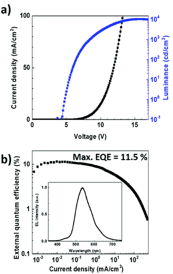
To verify experimentally these modelling results, we fabricated an OLED using the same multilayer structure but with a thickness of 35 nm for the TPBi layer. The electroluminescence data obtained with such a device architecture are reported in Fig. 8. Noticeably, in contrast to what was achieved with a TPBi film thickness of 55 nm, the emission peak at 427 nm can be observed in the EL spectrum. This fully supports the results obtained from the optical simulations and demonstrates the importance of the optical cavity effects on the dual emission from TADF OLEDs. The J–V curve and the EQE of the TADF OLED were also measured as a function of the current density. The maximum EQE value and luminance measured for this OLED were found to be as high as 11.5% and 10![[thin space (1/6-em)]](https://www.rsc.org/images/entities/char_2009.gif) 370 cd cm−2, respectively, providing evidence that not only the dual emission but also the overall performances of the EL device was improved after the optimization of the TPBi film thickness.
370 cd cm−2, respectively, providing evidence that not only the dual emission but also the overall performances of the EL device was improved after the optimization of the TPBi film thickness.
Conclusions
In summary, we designed and synthesized the novel TADF molecule (T-TRZ)-PTZ, which contains 4,6-bis-phenyl phenothiazine as donor units and 2-thiophene-1,3,5-triazine as acceptor unit. A simple and low-cost synthetic method based on cobalt catalysed cross-coupling was used to produce this light-emitting compound. This method fits with the asset of reducing OLED cost thanks to the used low-cost reagents. The photoluminescence spectrum of (T-TRZ)-PTZ in solution and film exhibits a dual emission which is due to the incorporation of phenothiazine unit in the molecular structure, resulting in the existence of two stable molecular conformations for (T-TRZ)-PTZ. The electroluminescence properties of (T-TRZ)-PTZ are then characterized in OLEDs and the best device exhibited maximum external quantum efficiency and luminance values of 11.5% and 10![[thin space (1/6-em)]](https://www.rsc.org/images/entities/char_2009.gif) 370 cd m−2, respectively. Based on experimental and optical simulations results, this study also provides new useful evidences that the OLED architecture must be carefully designed to optimize the dual emission in the electroluminescence spectrum. This latter result should be extremely relevant to further studies devoted to the development of high-efficiency white OLEDs based on single-component organic dual light-emitting molecules.
370 cd m−2, respectively. Based on experimental and optical simulations results, this study also provides new useful evidences that the OLED architecture must be carefully designed to optimize the dual emission in the electroluminescence spectrum. This latter result should be extremely relevant to further studies devoted to the development of high-efficiency white OLEDs based on single-component organic dual light-emitting molecules.
Experimental section
General information
All chemicals are reagent/analytical grade and used without further purification. Chromatographic purification of the products was accomplished using forced-flow chromatography on Geduran Silica Gel 60 40–63 mesh according to the method of Still. Thin-layer chromatography (TLC) was performed on Merck 0.20 mm silica gel 60-F254 plates. Visualisation of the developed chromatogram was performed by using UV light (254 nm). 1H, 13C, 19F NMR spectra were recorded on Bruker AC-300 (300 MHz, 75 MHz and 282 MHz respectively) as noted, and are internally referenced to residual solvent signals (CDCl3). Data for 1H, 13C and 19F NMR are reported as follows: chemical shift (δ ppm), multiplicity (s = singlet, d = doublet, t = triplet, q = quadruplet, m = multiplet), coupling constant and integration. High resolution mass spectra were obtained from the Ecole Polytechnique; Mass Spectral facility. Melting points were determined with a Stuart Automatic Melting Point SMP 40 and are uncorrected. All of the starting materials were purchased from the usual suppliers (Sigma-Aldrich, Alfa Aesar, and Acros Organics).Synthesis
1H-NMR (300 MHz, CDCl3): δ/ppm = 8.27 (dd, J = 3.9, 1.2 Hz, 1H), 7.77 (dd, J = 5.0, 1.2 Hz, 1H), 7.25–7.21 (m, 1H). 13C-NMR (75 MHz, CDCl3): δ/ppm = 171.8, 170.3, 138.1, 136.3, 135.2, 129.4. HRMS (EI+) (C7H3Cl2N3S): calculated m/z: 230.9425, found: 230.5421.
1H-NMR (300 MHz, CDCl3): δ/ppm = 8.73 (dd, J = 9.0, 5.6 Hz, 4H), 8.35 (dd, J = 3.8, 1.2 Hz, 1H), 7.66 (dd, J = 5.0, 1.2 Hz, 1H), 7.27–7.20 (m, 5H). 13C-NMR (75 MHz, CDCl3): δ/ppm = 170.7, 168.2, 166.0 (d, J = 253.2 Hz), 142.0, 132.5, 132.1 (d, J = 2.9 Hz), 131.8, 131.4 (d, J = 9.1 Hz), 128.7, 115.9 (d, J = 21.8 Hz). 19F-NMR (282 MHz, CDCl3): δ/ppm = −106.81. HRMS (EI+) (C19H11F2N3S): calculated m/z: 351.0642, found: 351.0641.
1H-NMR (300 MHz, CDCl3): δ/ppm = 8.79 (d, J = 8.6 Hz, 4H), 8.36 (d, J = 3.7 Hz, 1H), 7.65 (dd, J = 5.0, 1.2 Hz, 1H), 7.44 (d, J = 8.6 Hz, 4H), 7.26–7.24 (m, 1H), 7.21 (dd, J = 7.5, 1.6 Hz, 4H), 7.06 (td, J = 7.5, 1.6 Hz, 4H), 6.98 (td, J = 7.5, 1.2 Hz, 4H), 6.74 (dd, J = 7.5, 10.2 Hz, 4H). 13C-NMR (75 MHz, CDCl3): δ/ppm = 170.9, 168.1, 146.8, 143.1, 142.2, 133.1, 132.4, 131.6, 131.2, 128.7, 127.7, 127.2, 125.7, 125.2, 124.1, 120.3. HRMS (EI+) (C43H27N5S3): calculated m/z: 709.1429, found: 709.1416.
Photophysical measurements
For the photophysical measurements, the degassed toluene solution of (T-TRZ)-PTZ was placed in a quartz cuvette. In parallel, the organic thin film was deposited by thermal evaporation onto a precleaned fused silica substrate. UV-visible absorption and steady-state PL spectra were measured using a UV-2550 spectrometer (Shimadzu) and a Fluoromax-4 spectrophotometer (Horiba Scientific), respectively. The transient PL decay was measured by a streak camera (Hamamatsu Photonics C4334). The samples were placed under vacuum (<4 × 10⁻¹ Pa) and photoexcited by a nitrogen gas laser (Ken-X, Usho Optical Systems) delivering 500 ps pulses at a repetition rate of 20 Hz and emitting at 337 nm.OLED fabrication and measurements
The devices were prepared using precleaned indium tin oxide (ITO) substrates. The different organic layers were sequentially thermally evaporated under vacuum lower than 3 × 10⁻⁴ Pa. Finally, the LiF/Al electrodes were deposited through a shadow mask on top of the multilayer structure. The device active area was 4 mm2. To avoid any degradation and emission quenching due to oxygen and moisture, the OLEDs were encapsulated in a glovebox filled with nitrogen. The J–V–L characteristics were collected using a source meter (Keithley 2400, Keithley Instruments Inc.) and an absolute external quantum efficiency measurement system (C9920-12, Hamamatsu Photonics). An optical fiber connected to a spectrometer (PMA-12, Hamamatsu Photonics) was used to record the electroluminescence spectra.Conflicts of interest
There are no conflicts to declare.Acknowledgements
This work was supported by JST ERATO Grant Number JPMJER1305, Japan.References
- C. W. Tang and S. A. VanSlyke, Appl. Phys. Lett., 1987, 51, 913–915 CrossRef CAS.
- S. R. Forrest, M. A. Baldo, D. F. O'Brien, Y. You, A. Shoustikov, S. Sibley and M. E. Thompson, Nature, 1998, 395, 151–154 CrossRef.
- K. H. Kim, S. Lee, C. K. Moon, S. Y. Kim, Y. S. Park, J. H. Lee, J. Woo Lee, J. Huh, Y. You and J. J. Kim, Nat. Commun., 2014, 5, 4769 CrossRef CAS PubMed.
- J. C. Ribierre, S. G. Stevenson, I. D. W. Samuel, S. V. Staton and P. L. Burn, J. Disp. Technol., 2007, 3, 233–237 CAS.
- C. J. Chiang, A. Kimyonok, M. K. Etherington, G. C. Griffiths, V. Jankus, F. Turksoy and A. P. Monkman, Adv. Funct. Mater., 2013, 23, 739–746 CrossRef CAS.
- J. Xue, C. Li, L. Xin, L. Duan and J. Qiao, Chem. Sci., 2016, 7, 2888–2895 RSC.
- H. Uoyama, K. Goushi, K. Shizu, H. Nomura and C. Adachi, Nature, 2012, 492, 234–238 CrossRef CAS PubMed.
- A. Endo, M. Ogasawara, D. Takahashi, D. Yokoyama, Y. Kato and C. Adachi, Adv. Mater., 2009, 21, 4802–4805 CrossRef CAS PubMed.
- D. H. Kim, K. Inada, L. Zhao, T. Komino, N. Matsumoto, J. C. Ribierre and C. Adachi, J. Mater. Chem. C, 2017, 5, 1216 RSC.
- M. Y. Wong and E. Zysman-Colman, Adv. Mater., 2017, 29, 1605444 CrossRef PubMed.
- Y. Hao, D. H. Kim, X. K. Chen, A. S. D. Sandanayaka, J. U. Kim, E. Zaborova, G. Canard, Y. Tsuchiya, E. Y. Choi, J. W. Wu, F. Fages, J. L. Bredas, A. D'Aleo, J. C. Ribierre and C. Adachi, Chem. Mater., 2018, 30, 6702 CrossRef.
- D. Zhang, M. Cai, Y. Zhang, D. Zhang and L. Duan, Mater. Horiz., 2016, 3, 145–151 RSC.
- H. Wang, L. Xie, Q. Peng, L. Meng, Y. Wang, Y. Yi and P. Wang, Adv. Mater., 2014, 26, 5198–5204 CrossRef CAS PubMed.
- F. B. Dias, K. N. Bourdakos, V. Jankus, K. C. Moss, K. T. Kamtekar, V. Bhalla, J. Santos, M. R. Bryce and A. P. Monkman, Adv. Mater., 2013, 25, 3707–3714 CrossRef CAS PubMed.
- T. A. Lin, T. Chatterjee, W. L. Tsai, W. K. Lee, M. J. Wu, M. Jiao, K. C. Pan, C. L. Yi, C. L. Chung and K. T. Wong, Adv. Mater., 2016, 28, 6976–6983 CrossRef CAS PubMed.
- Q. Zhang, B. Li, S. Huang, H. Nomura, H. Tanaka and C. Adachi, Nat. Photonics, 2014, 8, 326–332 CrossRef CAS.
- H. Kaji, H. Suzuki, T. Fukushima, K. Shizu, K. Suzuki, S. Kubo, T. Komino, H. Oiwa, F. Suzuki, A. Wakamiya, Y. Murata and C. Adachi, Nat. Commun., 2015, 6, 8476 CrossRef CAS PubMed.
- S. Hirata, Y. Sakai, K. Masui, H. Tanaka, S. Y. Lee, H. Nomura, N. Nakamura, M. Yasumatsu, H. Nakanotani, Q. Zhang, K. Shizu, H. Miyazaki and C. Adachi, Nat. Mater., 2015, 14, 330–336 CrossRef CAS PubMed.
- Q. Zhang, H. kuwabara, W. J. Postcavage, S. Huang, Y. Hatae, T. Shibata and C. Adachi, J. Am. Chem. Soc., 2014, 136, 18070–18081 CrossRef CAS PubMed.
- D. H. Kim, A. D'Aleo, X. K. Chen, A. D. S. Sandanayaka, D. D. Yao, L. Zhao, T. Komino, E. Zaborova, G. Canard, Y. Tsuchiya, E. Y. Choi, J. W. Wu, F. Fages, J. L. Bredas, J. C. Ribierre and C. Adachi, Nat. Photonics, 2018, 12, 98 CrossRef CAS.
- H. Tanaka, K. Shizu, H. Nakanotani and C. Adachi, Chem. Mater., 2013, 25, 3766–3771 CrossRef CAS.
- Y. J. Cho, S. K. Jeon and Y. J. Lee, Adv. Opt. Mater., 2016, 4, 688–693 CrossRef CAS.
- Y. Im, M. Kim, Y. J. Cho, J. A. Seo, K. S. Yook and J. Y. Lee, Chem. Mater., 2017, 29, 1946–1963 CrossRef CAS.
- L. S. Cui, H. Nomura, Y. Geng, J. U. Kim, H. Nakanotani and C. Adachi, Angew. Chem., 2017, 129, 1593–1597 CrossRef.
- C. S. Oh, D. de Sa Pereira, S. H. Han, H. J. Park, H. F. Higginbotham, A. P. Monkman and J. Y. Lee, ACS Appl. Mater. Interfaces, 2018, 10, 35420–35429 CrossRef CAS PubMed.
- K. Wang, Y. Z. Shi, C. J. Zheng, W. Liu, K. Liang, X. li, M. Zhang, H. Lin, S. L. Tao, C. S. Lee, X. M. Ou and X. H. Zhang, ACS Appl. Mater. Interfaces, 2018, 19, 31515–31525 CrossRef PubMed.
- Y. J. Cho, S. K. Jeon, B. D. Chin, E. Yu and J. Y. Lee, Angew. Chem., 2015, 127, 5290–5293 CrossRef.
- H. Tanaka, K. Shizu, H. Nakanotani and C. Adachi, J. Phys. Chem. C, 2014, 118, 15985–15994 CrossRef CAS.
- I. Marghad, D. H. Kim, X. Tian, F. Mathevet, C. Gosmini, J. C. Ribierre and C. Adachi, ACS Omega, 2018, 3, 2254–2260 CrossRef CAS.
- D. G. Chen, T. C. Lin, Y. A. Chen, T. C. Lin, Y. T. Chen and P. T. Chou, J. Phys. Chem. C, 2018, 122, 12215–12221 CrossRef CAS.
- Y. J. Lien, T. C. Lin, C. C. Yang, Y. C. Chiang, C. H. Chang, S. H. Liu, Y. T. Chen, G. H. Lee, P. T. Chou, C. W. Lu and Y. Chi, ACS Appl. Mater. Interfaces, 2017, 9, 27090–27101 CrossRef CAS PubMed.
- D. G. Chen, T. C. Lin, C. L. Chen, Y. T. Chen, Y. A. Chen, G. H. Lee, P. T. Chou, C. W. Liao, P. C. Chiu, C. H. Chang, Y. J. Lien and Y. Chi, ACS Appl. Mater. Interfaces, 2018, 10, 12886–12896 CrossRef CAS PubMed.
- J. S. Ward, R. S. Nobuyasu, M. A. Fox, A. S. Batsanov, J. Santos, F. B. Dias and M. R. Bryce, J. Org. Chem., 2018, 83, 14431–14442 CrossRef CAS PubMed.
- K. Wang, C. J. Zheng, W. Liu, K. Liang, Y. Z. Shi, S. L. Tao, C. S. Lee, X. M. Ou and X. H. Zhang, Adv. Mater., 2017, 29, 1701476 CrossRef PubMed.
- M. Okazaki, Y. Takeda, P. Data, P. Pander, H. Higginbotham, A. P. Monkman and S. Minakata, Chem. Sci., 2017, 8, 2677–2686 RSC.
- P. Pander, R. Motyka, P. Zassowski, M. K. Etherington, D. Versano, T. J. da Silva, M. J. Caldas, P. Data and A. P. Monkman, J. Phys. Chem. C, 2018, 122, 23934–23942 CrossRef CAS.
- M. J. Frisch, G. W. Trucks, H. B. Schlegel, G. E. Scuseria, M. A. Robb, J. R. Cheeseman, G. Scalmani, V. Barone, B. Mennucci, G. A. Petersson, H. Nakatsuji, M. Caricato, X. Li, H. P. Hratchian, A. F. Izmaylov, J. Bloino, G. Zheng, J. L. Sonnenberg, M. Hada, M. Ehara, K. Toyota, R. Fukuda, J. Hasegawa, M. Ishida, T. Nakajima, Y. Honda, O. Kitao, H. Nakai, T. Vreven, J. A. Montgomery Jr, J. E. Peralta, F. Ogliaro, M. Bearpark, J. J. Heyd, E. Brothers, K. N. Kudin, V. N. Staroverov, R. Kobayashi, J. Normand, K. Raghavachari, A. Rendell, J. C. Burant, S. S. Iyengar, J. Tomasi, M. Cossi, N. Rega, J. M. Millam, M. Klene, J. E. Knox, J. B. Cross, V. Bakken, C. Adamo, J. Jaramillo, R. Gomperts, R. E. Stratmann, O. Yazyev, A. J. Austin, R. Cammi, C. Pomelli, J. W. Ochterski, R. L. Martin, K. Morokuma, V. G. Zakrzewski, G. A. Voth, P. Salvador, J. J. Dannenberg, S. Dapprich, A. D. Daniels, Ö. Farkas, J. B. Foresman, J. V. Ortiz, J. Cioslowski and D. J. Fox, Gaussian 09, D.01, Gaussian, Inc., Wallingford CT, 2009 Search PubMed.
- S. Hirata and M. Head-Gordon, Chem. Phys. Lett., 1999, 314, 291–299 CrossRef CAS.
- M. J. Peach, M. J. Williamson and D. J. Tozer, J. Chem. Theory Comput., 2011, 7, 3578–3585 CrossRef CAS PubMed.
- T. Lu and F. Chen, J. Comput. Chem., 2012, 33, 580–592 CrossRef CAS PubMed.
- C. Wang, C. Deng, D. Wang and Q. Zhang, J. Phys. Chem. C, 2018, 122, 7816–7823 CrossRef CAS.
- J. C. Ribierre, T. Aoyama, T. Muto, Y. Imase and T. Wada, Org. Electron., 2008, 9, 396 CrossRef CAS.
- T. Förster, Ann. Phys., 1948, 437, 55 CrossRef.
- A. Ruseckas, J. C. Ribierre, P. E. Shaw, I. D. W. Samuel, S. V. Staton and P. L. Burn, Appl. Phys. Lett., 2009, 95, 183305 CrossRef.
- K. J. Lee, J. H. Woo, E. S. Kim, Y. Xiao, X. Su, L. M. Mazur, A. J. Attias, F. Fages, O. Cregut, A. Barsella, F. Mathevet, L. Mager, J. W. Wu, A. D'Aleo and J. C. Ribierre, Phys. Chem. Chem. Phys., 2016, 18, 7875 RSC.
- A. D'Aleo, M. H. Sazzad, D. H. Kim, E. Y. Choi, J. W. Wu, G. Canard, F. Fages, J. C. Ribierre and C. Adachi, Chem. Commun., 2017, 53, 7003–7006 RSC.
- K. J. Lee, Y. U. Lee, F. Fages, J. C. Ribierre, J. W. Wu and A. D'Aleo, Nano Lett., 2018, 18, 1476 CrossRef CAS PubMed.
- V. Bulovic, V. Khalfin, G. Gu, P. Burrows, D. Garbuzov and S. R. Forrest, Phys. Rev. B, 1998, 58, 3730–3740 CrossRef CAS.
- J. Huang, J. Blochwitz-Nimoth, M. Pfeiffer and K. Leo, J. Appl. Phys., 2003, 93, 838 CrossRef CAS.
- S. K. So, W. K. Choi, L. M. Leung and K. Neyts, Appl. Phys. Lett., 1999, 74, 1939 CrossRef CAS.
- W. M. V. Wan, N. C. Greenham and R. H. Friend, J. Appl. Phys., 2000, 87, 2542 CrossRef CAS.
- S. Hofle, T. Lutz, A. Egel, F. Nickel, S. W. Kettlitz, G. Gomard, U. Lemmer and A. Colsmann, ACS Photonics, 2014, 1, 968–973 CrossRef.
- C. Schmitz, M. Thelakkat and H. W. Schmidt, Adv. Mater., 1999, 11, 821–826 CrossRef CAS.
- W. L. Barnes, J. Mod. Opt., 1998, 45, 661–699 CrossRef CAS.
- Z. B. Wang, M. G. Helander, X. F. Xu, D. P. Puzzo, J. Qiu, M. T. Greiner and Z. H. Lu, J. Appl. Phys., 2011, 109, 053107 CrossRef.
- L. Zhao, T. Komino, M. Inoue, J. H. Kim, J. C. Ribierre and C. Adachi, Appl. Phys. Lett., 2015, 106, 063301 CrossRef.
Footnote |
| † Electronic supplementary information (ESI) available: 1H-NMR, 13C-NMR, 19F-NMR, quantum chemistry calculations. See DOI: 10.1039/c8ra10393c |
| This journal is © The Royal Society of Chemistry 2019 |

