
 Open Access Article
 This Open Access Article is licensed under a Creative Commons Attribution-Non Commercial 3.0 Unported Licence
Atomic-scale investigation of the heterogeneous structure and ionic distribution in an ionic liquid using scanning transmission electron microscopy
Yuki Sugimoria,
Tomohiro Miyata ab,
Hiroki Hashiguchic,
Eiji Okunishic and
Teruyasu Mizoguchi*a
ab,
Hiroki Hashiguchic,
Eiji Okunishic and
Teruyasu Mizoguchi*a
aInstitute of Industrial Science, The University of Tokyo, 4-6-1 Komaba, Meguro, Tokyo 153-8505, Japan. E-mail: teru@iis.u-tokyo.ac.jp
bInstitute of Multidisciplinary Research for Advanced Materials, Tohoku University, 2-1-1, Katahira, Aoba, Sendai, Miyagi 980-8577, Japan
cJEOL Ltd., 3-1-2, Musashino, Akishima, Tokyo 196-8558, Japan
First published on 4th April 2019
Abstract
Ionic liquids show characteristic properties derived from them being composed of only molecular ions, and have recently been used as solvents for chemical reactions and as electrolytes for electrochemical devices. The liquid structures, i.e., ionic distributions, form when solutes are dissolved in ionic liquids and fundamentally affect the reactions and transfer efficiency in such solutions. In this study, we directly observe the liquid structure in a solution of the long-chain ionic liquid 1-octyl-3-methylimidazolium bromide (C8mim Br) and barium stearate (Ba(C17H35COO)2) using the annular dark-field method of scanning transmission electron microscopy (ADF-STEM). The ADF image shows a 10 nm-scale heterogeneity in the image intensity, which reflects the heterogeneous ionic distribution in the solution. The number density distributions of all the component ions (C8mim+, Br−, Ba2+, and C17H35COO−) were estimated from the ADF image intensity and then visualized. These ionic distribution maps depicted the spatial relationships between the ions at the sub-nanometer scale and revealed that the heterogeneity is largely derived from the large differences in size, charge distributions, and van der Waals interactions.
Introduction
Ionic liquids have attracted great attention as new solvents and media for absorption, separation, chemical reactions, ionic transfer, and other applications.1–6 For instance, cellulose dissolution and CO2 capture in ionic liquids have been extensively studied, and their use as electrolytes in batteries has been considered based on their high ionic density.1,3,4,7–12Ionic liquids are composed of at least two charged species (a cation and an anion), and in many cases, these ions have charged and neutral portions in their molecular structures. Owing to these molecular structures, ionic liquids can show properties similar to those of either inorganic molten salts or molecular liquids, or intermediate between them.
Furthermore, small angle scattering and molecular dynamics simulations have indicated that ionic liquids with long sidechains form nanoscale domain structures due to the aggregation of the ionic portions and the non-ionic sidechains of neighbouring molecules.13,14 In dilute solutions, solutes are reported to be preferentially solvated in specific domains of domain-forming ionic liquids.15 On the other hand, in concentrated solutions, the interaction between the solute and solvent may change the liquid structure; in other words, the solute and solvent may cooperatively form a new liquid structure different from that of the dilute solution. The solution structure could deform drastically depending on the charge, polarity, size, and structure of the solute and solvent molecules. In turn, the liquid structures and the solute/solvent distribution determine the solubility, relative positions, collision frequency, and mobility of the reactive and catalytic molecules, which affect the efficiency of chemical reaction and ionic transfer.
However, the local liquid structures and local heterogeneity of ionic liquids, which are formed at the sub-nanometer scale, have not yet been revealed due to the lack of high-spatial-resolution real-space analysis methods. Recently, the authors achieved the visualization of individual atoms in an ionic liquid using atomic-resolution scanning transmission electron microscopy (STEM).16,17 Annular dark-field (ADF) imaging using STEM has atomic-number (Z) sensitivity, which enables the identification of atomic species,18,19 and thus has the potential to identify the positions of the solute and solvent molecules in solution.
In this study, we apply atomic-resolution ADF-STEM for investigating the local liquid structure, i.e., the local distribution of the solute and solvent ions, in an ionic liquid solution. Barium stearate is dissolved in the ionic liquid 1-octyl-3-methylimidazolium bromide (C8mimBr); thus, four types of ions (C8mim+, Br−, Ba2+, and C17H35COO−) are present in the solution. The ionic distributions of all the constituent ions are estimated from the ADF image by resolving the relational expressions for the ADF image intensities, densities, and thicknesses of the respective ionic components. This manuscript aims to directly identify the spatial correlations between the constituent ions, and moreover, to discuss the origin of the heterogeneous ionic distribution based on the molecular structures of the ions.
Experiment
(i) Specimen preparation
We utilized the ionic liquid C8mimBr (Kanto Chemical Co. Inc., purity: 99%) as the solvent and barium stearate (Ba(C17H35COO)2) (FUJIFILM Wako Pure Chemical Corporation, purity: 95%) as the solute. We selected these materials because they have so large atomic numbers (Br, Z = 35 and Ba, Z = 56) that they are expected to be observed brightly by ADF-STEM. Moreover, Br and Ba are expected to be distinguished in an ADF-image owing to the difference of their atomic numbers. Furthermore, structural heterogeneities are expected to be observed owing to each different length of long alkyl chain in C8mimBr and barium stearate. Their molecular structures are shown in Fig. 1. First, barium stearate was dissolved in C8mimBr at a ratio of 0.015 M. Then, a mixture of the ionic liquid solution and ethanol was dropped onto a Quantifoil R1.2/1.3 holey carbon film (Quantifoil GmbH). Finally, the specimen was heated under vacuum to evaporate the ethanol and form freestanding thin films of the ionic liquid solution in the carbon film holes. Ionic liquids are generally nonvolatile; thus, these liquid films could be observed by TEM without solid sealing films. Further details are given in the previous report.20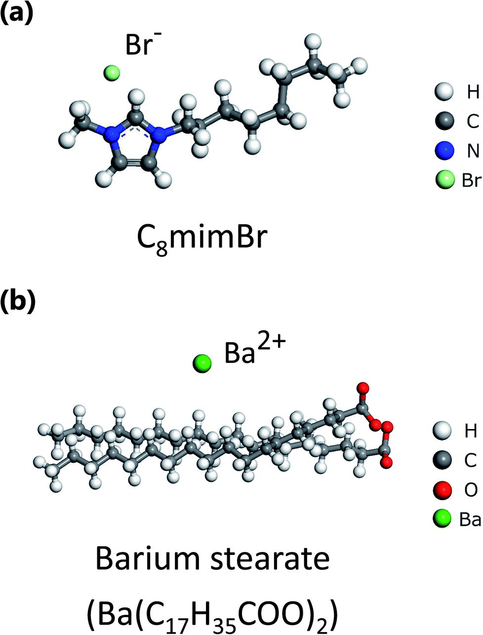 | ||
| Fig. 1 Molecular structures of (a) 1-octyle-3-methylimidazolium bromide (C8mimBr) and (b) barium stearate. | ||
(ii) STEM observation and image simulation
We observed the ultrathin liquid film using an aberration-corrected scanning transmission electron microscope (JEM-ARM200F NEOARM, JEOL Ltd.) equipped with a cold-type field-emission gun. The accelerating voltage was set to 200 kV. The beam current was ∼10 pA, and the probe diameter was ∼0.08 nm. The probe-forming aperture half-angle and the detection half-angle for the bright-field (BF) and ADF images were set to 18.5, 0–11 mrad, and 45–180 mrad, respectively. The dwell time was 40 μs per pixel, and the total acquisition time for an image was 41.9 s. All the experimental images were smoothed by a simple moving average filter of 5 × 5 pixels. The sample thickness was estimated by the electron energy-loss spectroscopy log-ratio method.21 The thickness of the the specimens shown in Fig. 2(a, c) and (b, d) were measured to be approximately 9 and 6.5 nm, respectively. The ADF-image simulations were performed using the multi-slice method (Dr. Probe package).22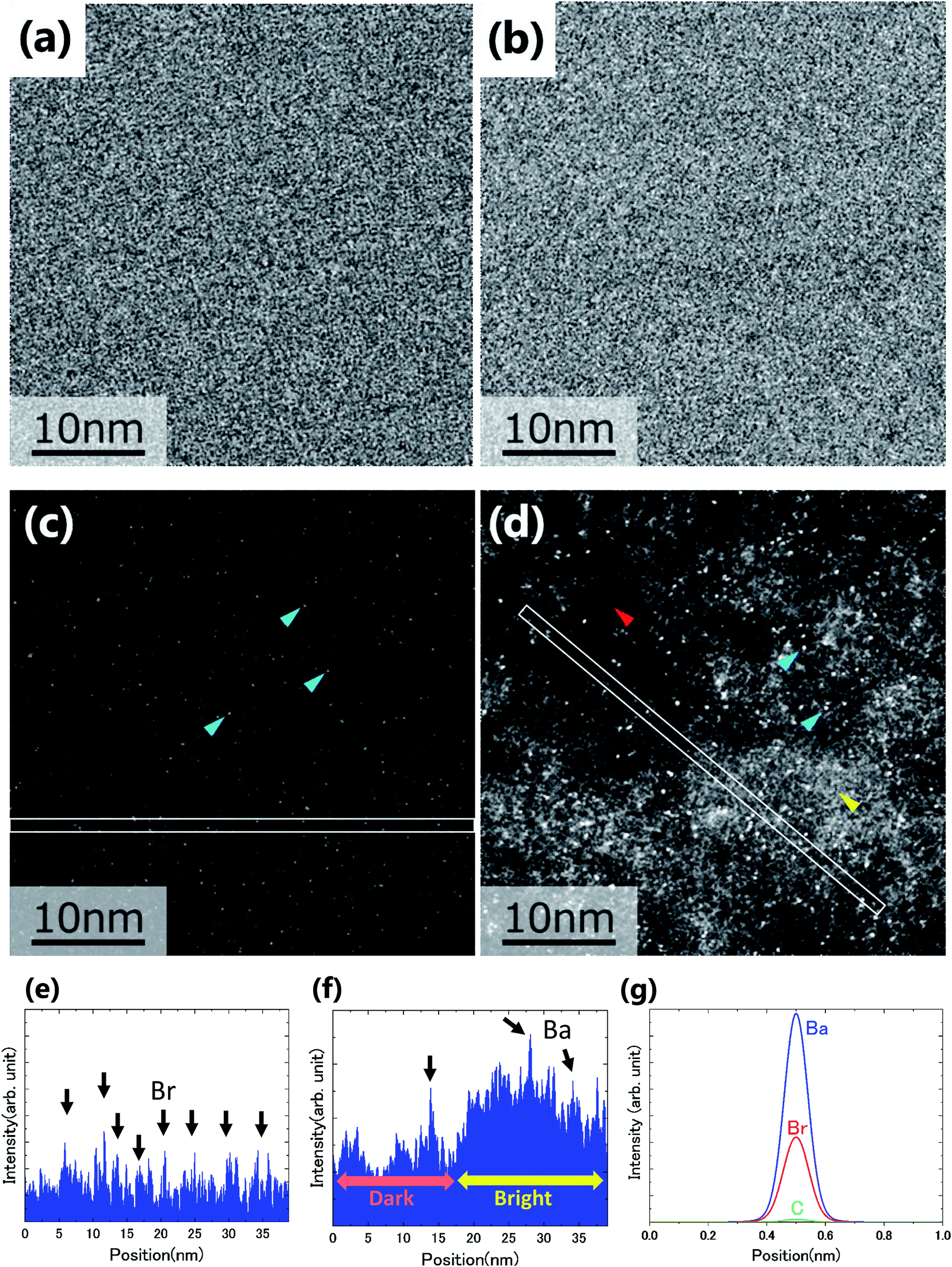 | ||
| Fig. 2 (a), (b) BF and (c), (d) ADF images of non-doped and solute-doped C8mimBr. (e) and (f) Intensity profiles along the lines in (c) and (d). (g) Simulated ADF intensity profiles of C, Br and Ba atoms in a vacuum. | ||
(iii) Spatial distribution analysis of Ba2+
The spatial distribution of Ba2+ was determined using the average nearest-neighbour distance analysis. The distance to the nearest-neighbour for each point was averaged for all the points. Then, the averaged value was compared to the expected value, and the standard deviation obtained under the random distribution.23(iv) Spatial distribution mapping of the constituent ions
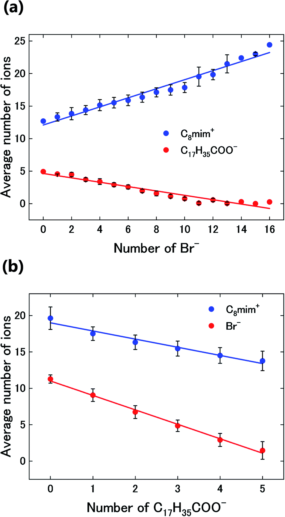
The spatial mapping was performed as follows. First, coarse-grained processing (binning of 11 × 11 pixels, 0.82 nm per pixel) was applied to Fig. 3(a) to obtain Fig. 3(b). The number distribution of the solute cation Ba2+ was extracted by determining the positions of the very bright spots. Then, the distributions of the other constituent ions (Br−, C8mim+, and C17H35COO−) were also estimated. Diagrammatic illustrations are shown in Fig. 3(c).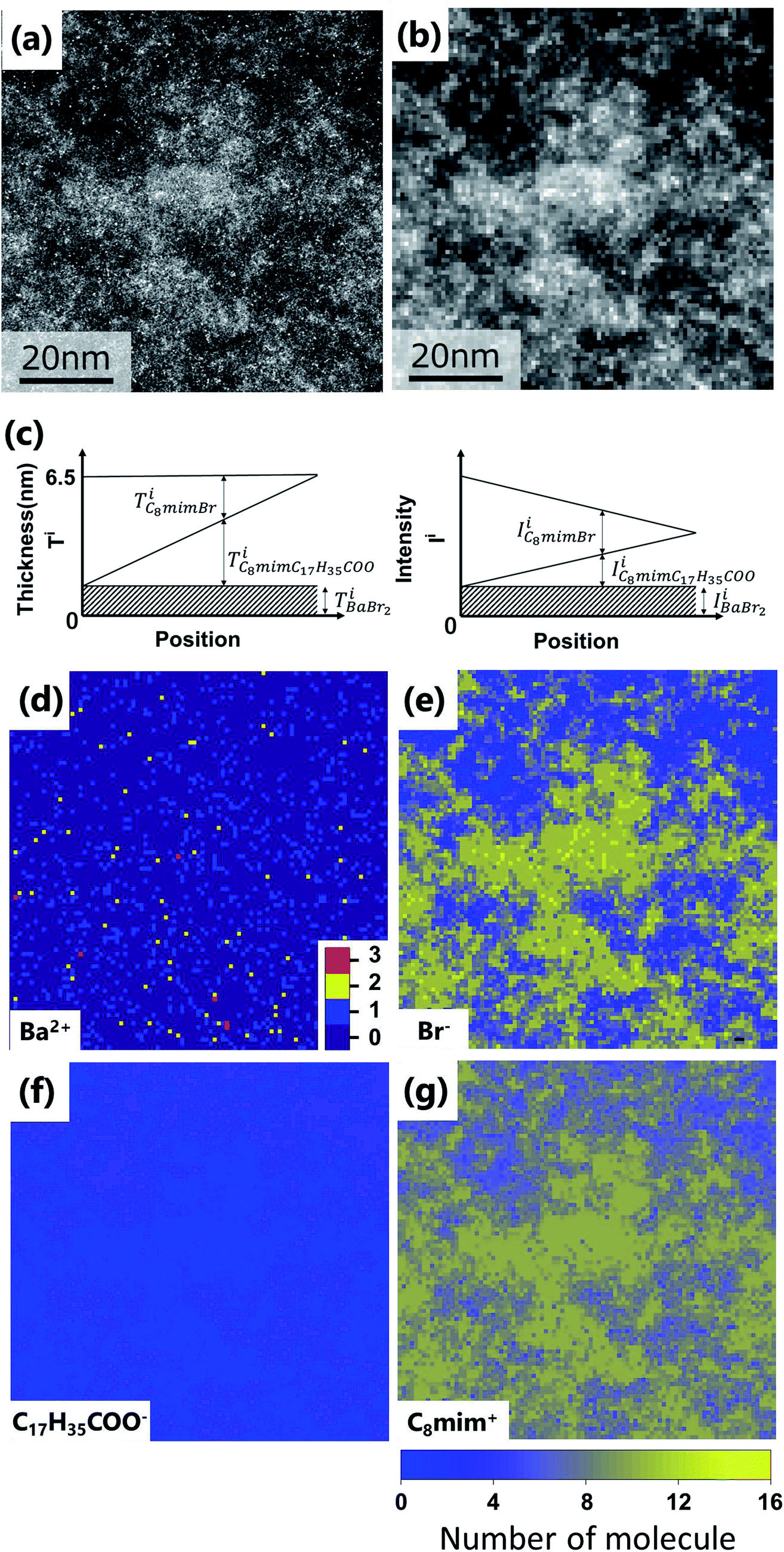 | ||
| Fig. 3 (a) Original images of Fig. 2(d). Fig. 2(d) is the upper left corner of this image. (b) Coarse-grained image from (a) by averaging 11 × 11 pixels (0.82 nm per pixel). (c) Thickness (left) and intensity (right) diagrams of the respective components for estimating the ionic distributions. (d–g) Estimated spatial distributions of Ba2+, Br−, C17H35COO−, and C8mim+, respectively. | ||
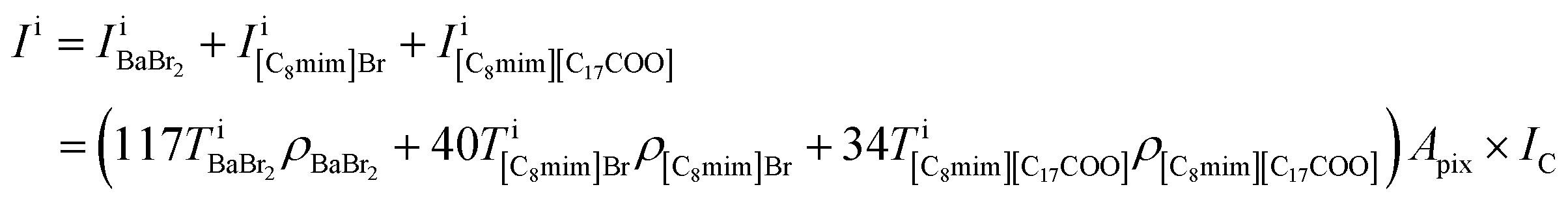
First, the ADF intensities of the constituent atoms, molecules, and molecular pairs were estimated using the ADF image simulations:
| IH = 0.05IC, IN = 1.80IC, IO = 2.34IC, IBr = 33.70IC, IBa = 66.47IC |
| IC8mim = 16.77IC, IC17COO = 24.47IC |
| IBaBr2 = (66.47 + 2 × 33.70)IC = 133.87IC, |
| I[C8mim]Br = (16.77 + 33.70)IC = 50.47IC |
| I[C8mim][C17COO] = (16.77 + 24.47)IC = 41.24IC, |
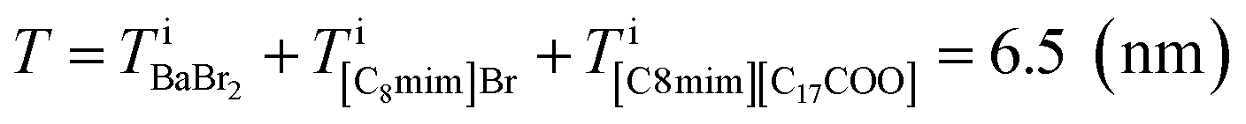
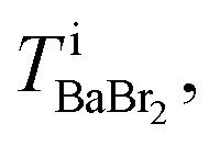
Based on the intensity relationships, we described the pixel intensities in the ADF image. The liquid film thickness was approximately separated into three layers of the ionic pairs: Ba2+ and two Br−, C8mim+ and Br−, and C8mim+ and C17H35COO−. The intensities of the separated layers were estimated with the following equations:
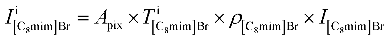
where Apix is the area of a coarse-grained pixel, 0.68 nm2. The densities were: ρBaBr2 = 9.68 nm−3 (BaBr2 (ref. 24)), ρ[C8mim]Br = 2.55 nm−3 (pure C8mimBr25), and ρ[C8mim][C17COO] = 1.12 nm−3 (estimated from ref. 26). The thickness was assumed to be constant over the whole image (T = 6.5 nm).

Because the number of Br− anions is much larger than that of C17H35COO− anions, Ba2+ was assumed to be solvated with Br− (BaBr2) for a simple consideration. The total intensity at pixel i is described as follows:
 can be estimated from the number of Ba2+ cations,
 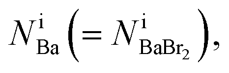 which has already been obtained, with the equation:
 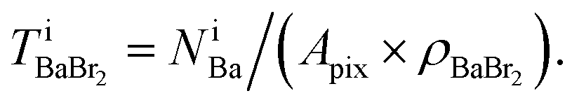 Thus, the equations about the intensities and thickness can be resolved to obtain the thickness of the components
 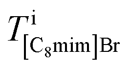 and
and 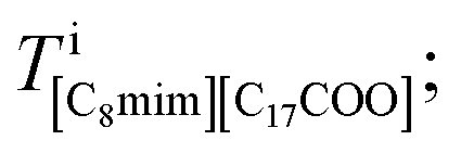 these values in turn can be used to give the number of ionic pairs in pixel i,
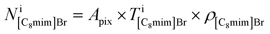

Finally, the numbers of the respective constituent ions in pixel i can be derived:


The equations fulfill local electrical neutrality:

(v) Relationships between the numbers of ions
The number of C8mim+ and Br− ions were averaged around the pixels containing C17H35COO−, as discussed later. In the same way, the average number of C8mim+ and C17H35COO− ions were graphed against the number of Br− ions. Ba2+ ions were not plotted here because their number was too small, statistically.To analyse the relationships between the distribution of Ba2+ and the other ions, the number of Br−, C8mim+, and C17H35COO− ions in the 8 pixels surrounding Ba2+ were averaged. The Pauling's ionic radii of Ba2+ and Br− are 0.135 and 0.195 nm;27 thus, the size of BaBr2 or pairs of Ba2+ and the ions with sidechains should be greater than 1.050 nm, which is larger than the coarse-grained pixel size of 0.82 nm. In addition, Ba2+ is not necessarily at the centre of the pixel. Thus, the surrounding pixels should be considered. The average numbers of Br− and the ions with sidechains around the pixels with and without Ba2+ are plotted in Fig. 5(b).
Results and discussion
(i) Comparison of the non-doped and solute-doped C8mimBr
Fig. 2(a)–(d) show the BF and ADF images of the non-doped and solute (barium stearate)-doped C8mimBr. Neither of the BF images shows characteristic contrast, indicating that the samples were in amorphous states (Fig. 2(a) and (b)). On the other hand, clear bright/dark contrast is observed in the ADF images (Fig. 2(c) and (d)). The ADF image intensity directly corresponds to the positions of the atoms, with the heavier atoms having much higher intensities. That is, the intensity contrast in the ADF image directly corresponds to the liquid structure. The intensity profiles along the lines in the ADF images are shown in Fig. 2(e) and (f).The ADF image of the non-doped specimen (C8mimBr only) shows many bright spots (Fig. 2(c)), which were assumed to be Br− ions because the atomic number of Br (ZBr = 35) is much larger than those of the other components (Z ≦ 7). While the Br− positions exhibited a higher intensity in the image than the others, the local mean intensity was almost constant over the entire image, indicating that the distribution of Br− did not exhibit any large heterogeneities (Fig. 2(e)).
On the other hand, the ADF image of the solute-doped specimen shows three distinguishable levels of contrast, namely, very bright spots (blue arrows), bright regions (yellow arrow), and dark regions (red arrow) (Fig. 2(d) and (f)). The sizes of the bright and dark regions were both measured to be approximately 10 nm.
(ii) Analysis of the ionic distributions
The intensity ratio of the clearest peaks among the very bright spots in Fig. 2(d) and the bright spots in Fig. 2(c) was around 2, indicating that the very bright spots in the solute-doped specimen were derived from an element much heavier than Br. In the present solution, the solute cation Ba2+ has a larger atomic number (Z = 56) than the other atoms (ZH = 1, ZC = 6, ZN = 7, ZO = 8, ZBr = 35). Fig. 2(g) shows the simulated ADF intensity of the individual C, Br, and Ba atoms in a vacuum. The intensity ratio of Ba to Br (IBa/IBr) was estimated to be 1.97, which is almost identical to the ratio measured in the experimental images. In other words, the very bright spots in the solute-doped specimens are the solute cation Ba2+.Next, we focused on the bright and dark regions in the image. The ADF image intensity is determined by the thickness, density, and composition, and the thickness of the liquid film was considered to be approximately equal in the local areas observed here due to the surface tension. Thus, this image would display the heterogeneity of the density and composition, i.e. the ionic distribution.
Subsequently, the number distributions of the ions (Ba2+, Br−, C8mim+, and C17H35COO−) estimated in the experiment section are displayed in Fig. 3(d)–(g).
First, Ba2+ seems to be dispersed rather than aggregated (Fig. 3(d)), but the average nearest neighbour analysis indicates that it has a 91% probability of exhibiting a concentrated distribution. The Br− distribution in Fig. 3(e) is similar to the original ADF image of Fig. 3(a), because the high intensity of Br (IBr) contributes to the ADF image much more than C8mim+ and C17H35COO−. Based on the figure, the Br− distribution shows large heterogeneity; Br−-rich and Br−-poor regions are formed at a scale of 10 nm. On the other hand, C17H35COO− shows the opposite contrast to the ADF image; that is, more C17H35COO− is observed in the Br−-poor regions (Fig. 3(f), (e) and 4). This indicates that the anions Br− and C17H35COO− are less miscible to each other in the solution.
Finally, Fig. 3(g) shows the C8mim+ distribution, which is similar to but more widely spread than that of Br−. This can be ascribed to the amount of the C8mim+. Namely, the amount of C8mim+ is much larger than that of Ba2+, thus C8mim+ is mainly used to compensate the negative charges of both Br− and C17H35COO−. Furthermore, by carefully observing the distribution of C17H35COO− (Fig. 3(f)), it is found that C17H35COO− does not have strong trend to bind with C8mim+. This trend can be clearly seen in Fig. 4(a) and (b). The amount of C8mim+ has proportional relationship to that of Br− (Fig. 4(a)), whereas it is inverse proportional to that of C17H35COO− (Fig. 4(b)). This point will be discussed later.
 | ||
| Fig. 4 Graphs of (a) the average number of C8mim+ and C17H35COO− ions against the number of Br− ions and (b) the average number of Br− and C8mim+ ions against the number of C17H35COO− ions. | ||
To clearly know the relationships among the ionic distributions, the average numbers of the ions were plotted against the number of C17H35COO− and Br− ions in Fig. 4(a) and (b), respectively. The numbers of Br− and C17H35COO− show an inverse proportional relationship because they are both negatively charged. On the other hand, Fig. 4(a) shows the linear increase of the number of C8mim+ ions against that of Br− to compensate the negative charge. The number of C8mim+ ions has inverse proportional to that of C17H35COO−.This can be simply ascribed to the Coulomb interaction between molecules/ions, that is Br− attracts C8mim+ ions than the C17H35COO− ions.
On the other hand, such simple explanation cannot be applied to the relationships between C8mim+ and C17H35COO−. As can be seen in Fig. 4(b), the number of C8mim+ decreases by increasing the number of C17H35COO− even though they should have attractive Coulomb interaction. This can be ascribed to the long alkali chain and weak ionicity of both molecules.
Next, the Ba2+ distribution in the liquid was investigated. In Fig. 5(a), the number density of Ba2+ (colored) is overlaid on that of Br− (black-white). Based on this figure, Ba2+ is mainly distributed in the Br−-rich regions. Here, we analysed the relationships between the average number of Br- ions and those of the ions with sidechains (C8mim+ and C17H35COO−) at pixels with and without Ba2+. The graph in Fig. 5(b) shows that the number of Br− ions increases where Ba2+ is present, while the number of ions with sidechains decreases. This tendency would be caused by the stronger attractive Coulomb interaction between Ba2+ and Br−.
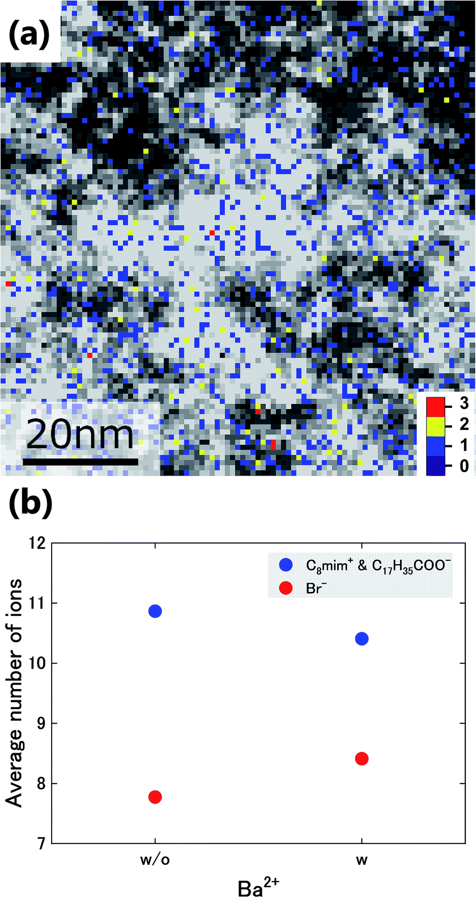 | ||
| Fig. 5 (a) Overlay of the images in Fig. 3(d) and (e). (b) Average number of Br− ions and of the ions with sidechains (C8mim+ and C17H35COO−) around the pixels with (w) and without (w/o) Ba2+. | ||
(iii) Discussion of the heterogeneous ionic distributions
We now discuss the reason why such a 10 nm-scale heterogeneous structure was formed in the present specimen. On the other hand, based on the small angle X-ray scattering, the structural heterogeneities of ionic liquids containing C8mim+ were reported to be approximately 2 nm.13,28 The 2 nm scale heterogeneity is found in our non-doped C8mimBr (Fig. 2(c)), but it is much smaller than the Ba-stearate doped specimen (Fig. 2(d)). So, the formation of the large heterogeneity can be ascribed to the Ba-stearate doping.The small and multivalent ions (Ba2+ and Br−) are known to show large Coulomb interactions, whereas the molecular ions with delocalized ionic portions and long noncharged sidechains (C8mim+ and C17H35COO−) have weaker ionic interactions than the charged ions, and instead show attractive van der Waals (vdW) interactions between the sidechains.27 These phenomena may account for the results: C17H35COO− ions aggregate with each other due to the strong vdW interactions between the very long alkyl chains, Br− ions gather separately from the C17H35COO− aggregate regions, and Ba2+ is likely to be located in Br−-rich regions. The main factor of the heterogeneous liquid structure would thus be the long alkyl chain of C17H35COO−, whereas the small contributions of the cations Ba2+ to the liquid structure might be caused by the low concentration and small size of Ba2+ ion.
This study revealed that, while ionic liquids with two components (a cation and an anion) such as C8mimBr show homogeneous distributions, those with four components (two cations and two anions) can exhibit heterogeneous ionic distributions originating from the preferential ionic aggregation and separation, which occurs because the interactions among the ions differ depending on the combinations and relative configurations of the ions. In addition, this study has demonstrated the potential of visualizing the spatial distributions of up to four types of ions in ionic liquids using thin specimens and ADF-STEM observation; this method will help in understanding the nanoscale heterogeneity in ionic liquids and designing ionic liquid solutions for effective solvents and transfer media.
Conclusions
To understand the solute- and solvent-ion distributions and liquid structures in a solution composed of the long-chain ionic liquid C8mimBr and the surfactant barium stearate, atomic-resolution ADF-STEM observation was utilized. The ADF image of the thin liquid film of the solution shows a 10 nm-scale heterogeneity in its intensity, with bright and dark regions that are attributed to the heterogeneous distribution of the constituent ions in the solution. The spatial distribution of the solute cation Ba2+, solvent anion Br−, solvent cation C8mim+ and solute anion C17H35COO− were identified by image processing and the relationships of the ADF intensities, densities, and thicknesses of the constituent ions.Concerning the heterogeneity of the molecule/ion distributions, Br− and C17H35COO− show strong heterogeneity while the heterogeneity is weaker in Ba2+ and C8mim+. The heterogeneous structure can mainly be attributed to the long alkyl chain of C17H35COO−, which would create strong vdW interactions between sidechains.
This paper has demonstrated the direct visualization of the heterogeneous structure and their forming mechanisms via the atomic-resolution ADF-STEM. Our method would strongly support the elucidation and development of ionic liquid solutions from the microscopic perspective.
Conflicts of interest
There are no conflicts to declare.Acknowledgements
The STEM measurements were conducted at JEOL Ltd. This study was supported by the Mitsubishi Science Foundation (27143), Grants-in-Aid for Scientific Research from Ministry of Education, Culture, Sports, Science and Technology (MEXT) (no. 25106003, 26630302, 26249092, and JP17H06094), and the Japan Science and Technology Agency (JST)–Precursory Research for Embryonic Science and Technology (PRESTO) (JPMJPR16NB 16814592).Notes and references
- M. Armand, F. Endres, D. R. MacFarlane, H. Ohno and B. Scrosati, Nat. Mater., 2009, 8, 621–629 CrossRef CAS PubMed
.
- Z. Lei, B. Chen, Y. M. Koo and D. R. Macfarlane, Chem. Rev., 2017, 117, 6633–6635 CrossRef PubMed
- Y. Yamada, K. Usui, K. Sodeyama, S. Ko, Y. Tateyama and A. Yamada, Nat. Energy, 2016, 1, 1–9 Search PubMed
- M. C. Lin, M. Gong, B. Lu, Y. Wu, D. Y. Wang, M. Guan, M. Angell, C. Chen, J. Yang, B. J. Hwang and H. Dai, Nature, 2015, 520, 325–328 CrossRef PubMed
- M. Semsarilar and S. Perrier, Nat. Chem., 2010, 2, 811–820 CrossRef CAS PubMed
- M. Asadi, K. Kim, C. Liu, A. V. Addepalli, P. Abbasi, P. Yasaei, P. Phillips, A. Behranginia, J. M. Cerrato, R. Haasch, P. Zapol, B. Kumar, R. F. Klie, J. Abiade, L. A. Curtiss and A. Salehi-Khojin, Science, 2016, 353, 467–470 CrossRef CAS PubMed
- R. P. Swatloski, S. K. Spear, J. D. Holbrey and R. D. Rogers, J. Am. Chem. Soc., 2002, 124, 4974–4975 CrossRef CAS PubMed
- C. Cadena, J. L. Anthony, J. K. Shah, T. I. Morrow, J. F. Brennecke and E. J. Maginn, J. Am. Chem. Soc., 2004, 126, 5300–5308 CrossRef CAS PubMed
- H. Zhang, J. Wu, J. Zhang and J. He, Macromolecules, 2005, 38, 8272–8277 CrossRef CAS
- E.-K. Shin and B.-C. Lee, J. Chem. Eng. Data, 2008, 53, 2728–2734 CrossRef CAS
- M. Klähn and A. Seduraman, J. Phys. Chem. B, 2015, 119, 10066–10078 CrossRef PubMed
- J. L. Anderson, J. N. K. Dixon, E. J. Maginn and J. F. Brennecke, J. Phys. Chem. B, 2006, 110, 15059–15062 CrossRef CAS PubMed
- A. Triolo, O. Russina, H.-J. Bleif and E. Di Cola, J. Phys. Chem. B, 2007, 111, 4641–4644 CrossRef CAS PubMed
- J. N. A. Canongia Lopes and A. A. H. Pádua, J. Phys. Chem. B, 2006, 110, 3330–3335 CrossRef CAS
- K. Fruchey and M. D. Fayer, J. Phys. Chem. B, 2010, 114, 2840–2845 CrossRef CAS
- T. Miyata, F. Uesugi and T. Mizoguchi, Sci. Adv., 2016, 3, e1701546 CrossRef
- T. Miyata and T. Mizoguchi, Microscopy, 2018, 67, i162–i167 CrossRef
- T. Mizoguchi, S. D. Findlay, A. Masuno, Y. Saito, K. Yamaguchi, H. Inoue and Y. Ikuhara, ACS Nano, 2013, 7, 5058–5063 CrossRef CAS
- P. D. Nellist and S. J. Pennycook, Ultramicroscopy, 1999, 78, 111–124 CrossRef CAS
- T. Miyata and T. Mizoguchi, Ultramicroscopy, 2017, 178, 81–87 CrossRef CAS
- T. Malis, S. C. Cheng and R. F. Egerton, J. Electron Microsc. Tech., 1988, 8, 193–200 CrossRef CAS PubMed
- J. Barthel, Ultramicroscopy, 2018, 193, 1–11 CrossRef CAS
- P. J. Clark and F. C. Evans, Ecology, 1954, 35, 445–453 CrossRef
- Z. Yan, G. Gundiah, G. A. Bizarri, E. C. Samulon, S. E. Derenzo and E. D. Bourret-Courchesne, Nucl. Instrum. Methods Phys. Res., Sect. A, 2014, 735, 83–87 CrossRef CAS
- C. Kolbeck, J. Lehmann, K. R. J. Lovelock, T. Cremer, N. Paape, P. Wasserscheid, A. P. Fröba, F. Maier and H. P. Steinrück, J. Phys. Chem. B, 2010, 114, 17025–17036 CrossRef CAS PubMed
- C. Ye and J. M. Shreeve, J. Phys. Chem. A, 2007, 111, 1456–1461 CrossRef CAS PubMed
- R. D. Shannon, Acta Crystallogr., 1976, 751 CrossRef CAS
- O. Russina, A. Triolo, L. Gontrani, R. Caminiti, D. Xiao, L. G. Hines, R. A. Bartsch, E. L. Quitevis, N. Plechkova and K. R. Seddon, J. Phys.: Condens. Matter, 2009, 21, 424121 CrossRef
| This journal is © The Royal Society of Chemistry 2019 |