DOI:
10.1039/C8RA10204J
(Paper)
RSC Adv., 2019,
9, 6907-6918
Electrochemistry of chemiluminescent novel hybrid nanocomposites based on polyaniline and hydrolyzed pectin with CdS nanoparticles†
Received
12th December 2018
, Accepted 15th February 2019
First published on 28th February 2019
Abstract
Novel hybrid nanocomposites based on polyaniline (PANi), hydrolyzed pectin (HPEc) and CdS nanoparticles (NPs) as electrochemiluminescent biomaterials were prepared. The samples were fabricated via heterogeneous chemical polymerization and studied by FTIR, XRD, SEM, EDX, UV/Vis, TGA and DMTA analyses. The CdS@HPEc-g-PANi nanocomposite was produced via in situ coprecipitation of CdS NPs by direct addition of aqueous cadmium nitrate and sodium sulfide solutions into the polymerization system containing PANi and HPEc. The mCdS@HPEc-g-PANi nanocomposite was synthesized via a new two-step surface modification strategy. The as-prepared CdS NPs synthesized via the chemical precipitation method were modified with epichlorohydrin as an organic reagent to obtain modified CdS (mCdS) and subsequently modified with HPEc and polymerized with aniline hydrochloride to produce mCdS@HPEc-g-PANi. The more smooth morphology of the mCdS@HPEc-g-PANi relative to the CdS@HPEc-g-PANi was approved by the SEM images. The cyclic voltammetry and electrochemical impedance spectroscopy analyses were performed on the samples to evaluate electrochemical properties and the results have indicated the reinforcing effect of the nanoparticles on the electrochemical properties of the nanocomposites. The electrical conductivity measurements by the four probe method have shown a significant increase of electrical conductivity in the presence of the CdS-nanoparticles. The CL experiments confirmed the chemiluminescence effect in the nanocomposites and also higher luminescence intensity for mCdS@HPEc-g-PANi relative to the CdS@HPEc-g-PANi nanocomposite owing to better dispersion of CdS NPs in the former sample.
1 Introduction
Within the last decade conducting polymer nanocomposites have been notable subjects in many studies for fabricating innovative materials with electrochemical applications.1 PANi is one of the most practical conducting polymers which, because of its low cost, facile synthesis, high chemical and environmental stability, exchangeable electrical conductivity and good specific capacitance, holds great promise for many applications within electrochemistry fields.2–4 Nanomaterials, due to an increase of surface-volume ratio and reduction of electron transfer resistance, cause the reinforcement of electrochemical performance.5,6 During the last few years, inorganic semiconductor nanoparticles such as PbS, ZnS, CdSe and CdS due to their unique electrical, optical and electrochemical properties have been discussed in numerous electrochemical and electro-chemiluminescence (ECL) fields.7–10 CdS semiconductors with a band gap of 2.42 eV indicate superior optical, photophysical and photochemical properties.5 PANi due to its excellent conductivity, high chemical and electrochemical stability is a good host matrix for the inorganic semiconductors.5 Composites composed of conducting polymers and inorganic semiconductors indicate the reinforced mechanical, electrical and thermal properties11 and are valuable for commercial applications like nanoelectronics,12 biosensors,13 photovoltaic and light-emitting diodes.14 These materials are also predicted as effectual and promising electrode materials in various electrochemical devices.5 PANi/CdS nanocomposites are generally prepared by an electrochemical method15 and colloidal dispersion.16,17 Moreover direct addition of nanoparticles into polymer matrix during polymerization has been recognized as an effective route to be responsible a relatively homogeneous distribution of nanoparticles.5 In order to gain desirable properties such as processability, hydrophilicity and biocompatibility, the samples were synthesized in the presence of a biopolymer such as pectin. Some studies have been performed on preparation and characterization of composites based on PANi/biopolymer for the purpose of electrochemical applications.18–20 Pectin is a natural, non-toxic and biocompatible polysaccharide with high molecular weight consisted of three distinct structural units including homogalacturonan (HG), rhamnogalacturonan I (RG I) and rhamnogalacturonan II (RG II).21 In this work, conductive copolymer based on PANi and HPEc and its hybrid nanocomposites with CdS and mCdS were produced and characterized by various characterization techniques. The samples were investigated in terms of electrical conductivity, chemiluminescence and electrochemical properties to introduce the possible application of the nanocomposites as electrochemiluminescent biomaterials.
2 Experimental
2.1 Materials and methods
Aniline monomer was provided from Merck (Schuchardt Germany) and doubly distilled to remove any impurities. Pectin was purchased from Exir Company (Austria). Ammonium persulfate (APS) was obtained from Asia Pajouhesh Ltd. (Amol, Iran). Cadmium nitrate (Cd(NO3)2), sodium sulfide (Na2S), epichlorohydrin, paratoluenesulfonic acid (PTSA) and other materials and solvents containing hydrochloric acid (HCl), sodium hydroxide (NaOH), toluene, dimethyl sulfoxide (DMSO), 1-methyl 2-pyrrolidone (NMP) and acetone were supplied from Merck (Schuchardt, Germany). Polyvinyl butyral (PVB) was bought from Polymer Pishrafteh Dana (Tehran, Iran).
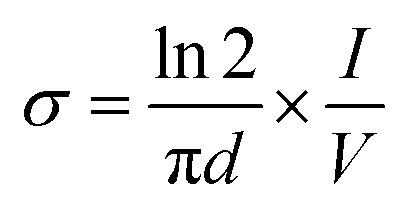
The Fourier transform infrared (FTIR) experiments were performed by a BRUKER TENSOR27 FTIR spectrometer (Germany) using KBr tablet and the spectra were recorded in the range of 400–4000 cm−1. The X-ray diffraction (XRD) patterns were obtained by a Philips PW1730 X-ray diffractometer (Netherlands) at a scan rate of 10 °C min−1. The scanning electron microscopy (SEM) and energy dispersive X-ray (EDX) analyses were carried out by a FESEM-EDX-map (FESEM TESCAN MIRA Π, Czech). The thermogravimetric analyses (TGA) were carried out by a TA Q50 V6.3 Build 189 (Germany) device under Ar atmosphere at a heating rate of 20 °C min−1 from room temperature to 600 °C. The dynamic mechanical thermal (DMTA) analyses of the samples were performed by a DMA1 METTLER TOLEDO (stare system, Switzerland) over a temperature range of −20 °C to 350 °C. The UV/Vis absorption was recorded by a UV-Vis array spectrophotometer Photonix Ar 2017 in the range of 200–800 nm. The electrochemical experiments were performed by a Biological SP150 electrochemical device. All the measurements were carried out in a three-electrode system with a copper electrode as the working electrode (WE), platinum electrode as the counter electrode (CE) and Ag/AgCl as the reference electrode (RE). The electrochemical impedance spectroscopy (EIS) analyses were performed over an operating frequency range of 100 kHz to 100 MHz in an open circuit potential (OCP) system. The cyclic voltammetry (CV) experiments were done with a potential scanning between −0.2 to 1.4 V at scan rates of 10 to 200 mV s−1. The experiments were performed in a acetate buffer solution containing [Fe(CN)6]3−/4− and the WE was coated with 0.06–0.1 g of the samples dispersed in 0.12 g of PVB resin dissolved in NMP. The chemiluminescence (CL) experiments were conducted by a commercial chemiluminescence analytical testing device (Bertoled Company, Germany) equipped with a photomultiplier tube detector (PMT). The electrical conductivity measurements were carried out by four-probe method. For this purpose, the powdered samples were prepared in pellet form (diameter: 13 mm, thickness: 1 mm) at pressure of 14 MPa. The electrical conductivity was defined as the below:
where,
σ is the conductivity (S cm
−1),
I is the applied current (mA),
V is the voltage drop (mV) and
d is the sample thickness (cm).
2.2 Preparation of HPEc-g-PANi copolymer via solution polymerization
To fabricate this sample, primarily, pectin was hydrolyzed in basic medium by NaOH solution at 50 °C temperature to produce hydrolyzed pectin (HPEc). A facile one step procedure was used for the synthesis of HPEc-g-PANi copolymer. Firstly, 1 g HPEc was dissolved in 80 mL doubly distilled water in a round-bottomed reactor equipped with a magnetic stirrer. The reactor was immersed in a thermostated oil bath and after complete dissolution of HPEc, an aqueous solution containing 5 mmol APS was added slowly into the above solution under inert gas at 50 °C to radicalize the HPEc molecules. Subsequently, 2 g aniline in 50 mL (1 M HCl) was poured into the above solution under continuous stirring. To complete the polymerization of the PANi on HPEc, another APS solution with the molar ratio of 1![[thin space (1/6-em)]](https://www.rsc.org/images/entities/char_2009.gif) :2 (oxidant to aniline) was added drop-wise into the polymerization mixture. The reaction was allowed to perform for 24 h under inert gas at 50 °C to obtain a dark green product. The resulting crude product was collected by centrifugation, washed successively with doubly distilled water and acetone, and then dried in an oven at 40 °C.
:2 (oxidant to aniline) was added drop-wise into the polymerization mixture. The reaction was allowed to perform for 24 h under inert gas at 50 °C to obtain a dark green product. The resulting crude product was collected by centrifugation, washed successively with doubly distilled water and acetone, and then dried in an oven at 40 °C.
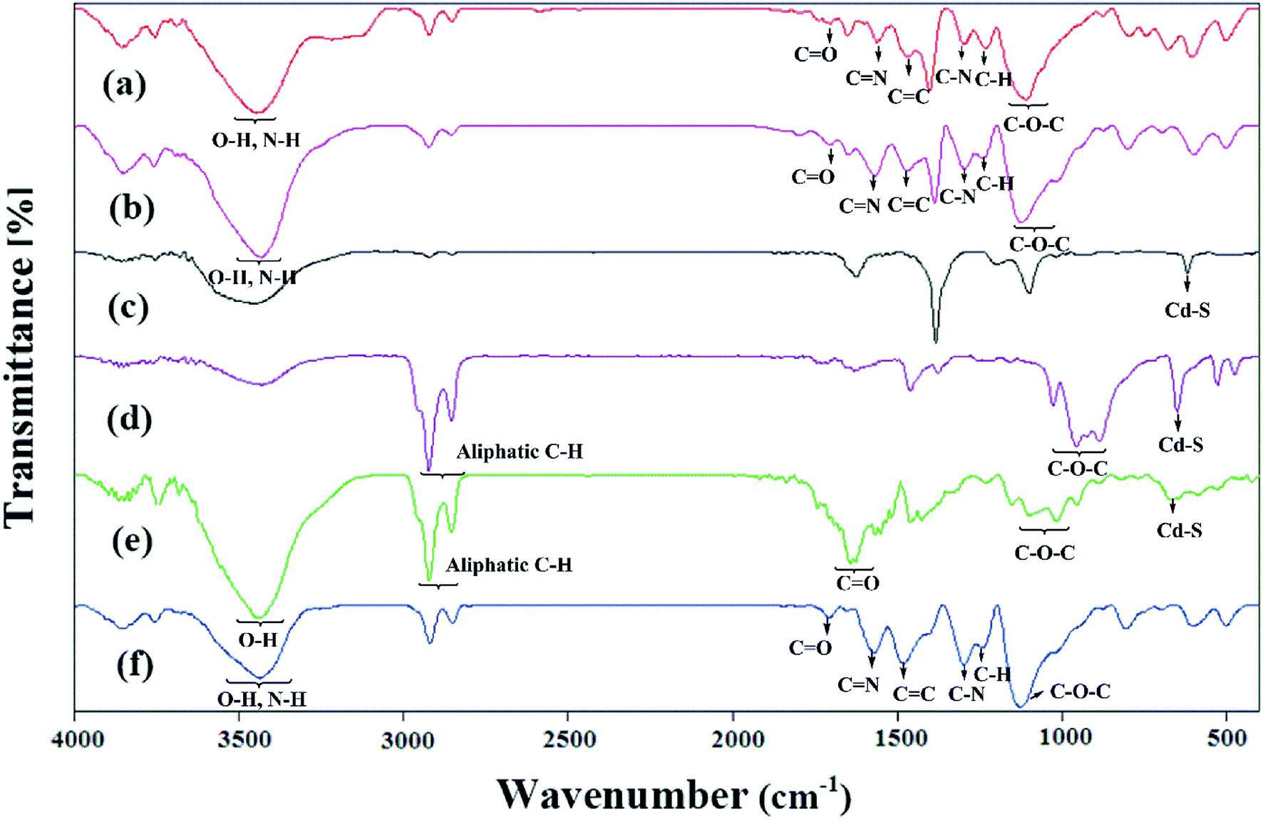
IR spectra data (KBr, ν cm−1): 1474 (C![[double bond, length as m-dash]](https://www.rsc.org/images/entities/char_e001.gif) C), 1561 (CN), 1231 (C–H), 1297 (C–N), 1706 (CO), 1109 (C–O–C), 3447 (overlapped O–H, N–H).
C), 1561 (CN), 1231 (C–H), 1297 (C–N), 1706 (CO), 1109 (C–O–C), 3447 (overlapped O–H, N–H).
2.3 Preparation of CdS@HPEc-g-PANi hybrid nanocomposite
The preparation of CdS@HPEc-g-PANi hybrid nanocomposite was performed via in situ polymerization of aniline and HPEc by APS initiator in the presence of Cd(NO3)2 and Na2S aqueous solutions. In a 250 mL three necked round-bottom flask with inlet and outlet of inert gas, 0.5 g HPEc was dissolved in 40 mL distilled water and agitated continuously at 50 °C. The reaction medium was degassed for 20 min. Then 0.6 g APS in 7 mL distilled water was added slowly into the HPEc solution. To this solution, 1 g aniline in 25 mL HCl (1 M) was added and the components were constantly stirred under inert gas. The polymerization mixture was reacted with further initiator solution (1.22 g APS in 15 mL distilled water) to complete the polymerization of PANi. Subsequently, 10 mL Cd(NO3)2 and Na2S aqueous solutions (0.5 M) were added into the reaction mixture under sonication and the reaction was allowed to continue for 24 h. After completion of reaction, the resulting precipitates were separated by filtering, washed with distilled water and acetone and dried overnight in an oven at 40 °C.
IR spectral data (KBr, ν cm−1): 1467 (CC), 1568 (CN), 1242 (C–H), 1297 (C–N), 1125 (C–O–C), 1705 (CO), 602 and 697 (Cd–S), 3432 (overlapped O–H, N–H).
2.4 Preparation of mCdS@HPEc-g-PANi hybrid nanocomposite
To produce mCdS@HPEc-g-PANi hybrid nanocomposite, primarily the CdS NPs were prepared from 50 mL aqueous solutions of Cd(NO3)2 and Na2S (0.5 M) under N2 gas at 80 °C. The resulting precipitates were separated via centrifugation with 4000 rpm and washed with distilled water and acetone and dried at a vacuum oven at 40 °C. The obtained CdS product was treated with epichlorohydrin as modifying agent to obtain mCdS product. For this purpose, in a 100 mL two-necked round bottom flask equipped with a magnetic stirrer, 1 g CdS was dispersed in 25 mL toluene then treated with 1 mL epichlorohydrin. The reaction was maintained for 72 h under reflux and N2 gas. The resultant product was filtered, washed with distilled water and acetone and stored in an oven at 40 °C to dry. To synthesize mCdS@HPEc product, 0.34 g mCdS was reacted with an aqueous solution containing 0.5 g HPEc in 40 mL distilled water in the presence of PTSA as an acidic catalyst. The reaction was performed at 70 °C for 24 h and resulting product was separated via filtration, washed with distilled water and acetone and dried in an oven at 50 °C. The obtained mCdS@HPEc product (0.34 g) was dispersed in 25 mL distilled water and mixed with 0.6 g APS (in 7 mL distilled water). After 30 min, 0.5 g aniline in 25 mL HCl (1 M) was added into the above dispersion to produce mCdS@HPEc-g-PANi. The polymerization reaction was maintained under stirring and N2 atmosphere for 24 h at 50 °C. On completion of reaction, the resulting precipitates were collected by filtering, washed repeatedly with distilled water and acetone and dried in an oven at 40 °C.
IR spectral data (KBr, ν cm−1): 1027 (C–O–C), 2854–2924 (C–H), 650 (Cd–S), 1482 (CC), 1571 (CN), 1242 (C–H), 1298 (C–N), 1129 (C–O–C), 2852,2929 (C–H), 1707 (CO), 602 (Cd–S), 3437 (overlapped O–H, N–H).
The schematic illustration of the synthetic path of the prepared samples is presented in Fig. 1 and 2.
 |
| | Fig. 1 Schematic illustration for the synthesis of HPEc-g-PANi copolymer and CdS@HPEc-g-PANi hybrid nanocomposite. | |
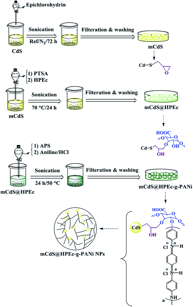 |
| | Fig. 2 Explanation of the synthetic path and possible schematic image of mCdS@HPEc-g-PANi hybrid nanocomposite. | |
3 Results and discussion
3.1 Spectroscopic characterization
The FTIR spectra of the samples are reported in Fig. 3. The expected characteristic peaks of the PANi and HPEc were found in the IR spectrum of HPEc-g-PANi. The main peaks at ∼1474, ∼1561, ∼1231, ∼1297, ∼1706, ∼1109 and ∼3447 cm−1 are ascribed to CC and CN stretching of benzenoid and quinoid rings, C–H and C–N stretching of benzenoid units of PANi, CO, C–O–C and O–H stretching vibrations of HPEc respectively that support the successful formation of the copolymer. In the IR spectrum of CdS@HPEc-g-PANi beside the appearance of the absorption bands of the PANi and HPEc at the corresponding regions, the peaks at ∼602 and ∼697 cm−1 can be corresponding to the CdS vibrations.22 In CdS@HPEc-g-PANi nanocomposite, the absorption peak related to CC stretching of benzenoid structure was shifted to lower region from ∼1474 cm−1 to ∼1467 cm−1 compared to the HPEc-g-PANi. This shift may be due to chelating interactions between CdS and nitrogen atoms of benzenoid units on the surface of PANi in CdS@HPEc-g-PANi.23 In the IR absorption spectrum of the mCdS, the vibrations between ∼886 and ∼1027 cm−1 are pertained to C–O–C bond stretching arising from the formation of epoxide groups on CdS and the peaks of ∼2854–2924 cm−1 and ∼650 cm−1 are associated to aliphatic C–H stretching of epoxide ring and CdS vibrations respectively. The stabilization of HPEc on mCdS was characterized via characteristic peaks in 956–1153 cm−1 corresponding to C–O–C bonds and ∼1642 cm−1 attributed to CO stretching vibration. For the mCdS@HPEc-g-PANi nanocomposite, the characteristic absorption peaks of the PANi, HPEc and CdS can be observed at the corresponding areas.
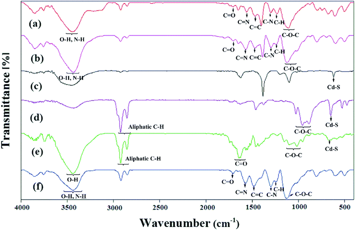 |
| | Fig. 3 The IR spectra of (a) HPEc-g-PANi, (b) CdS@HPEc-g-PANi, (c) CdS, (d) mCdS, (e) mCdS@HPEc and (f) mCdS@HPEc-g-PANi. | |
3.2 Morphological characterization
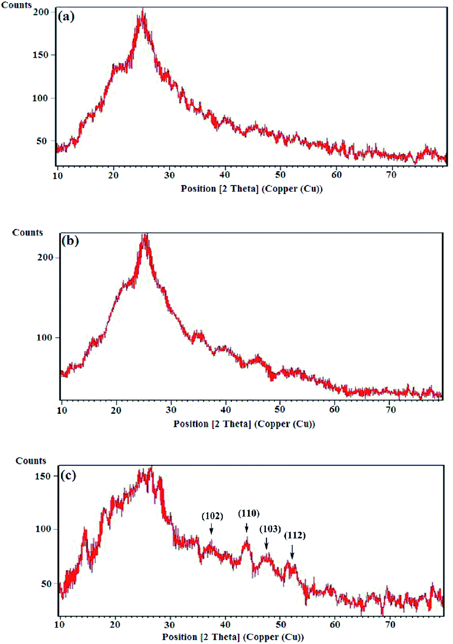
3.2.1 XRD analysis. The crystallographic studies of the samples were carried out by the XRD analyses and the diffraction patterns are exhibited in Fig. 4. The X-ray diffraction patterns of the HPEc-g-PANi, CdS@HPEc-g-PANi and mCdS@HPEc-g-PANi displayed the peaks at 2θ = 24.95°, 25.65° and 26.55° attributed to the characteristic crystalline planes of PANi and CdS components of hybrid nanocomposites.24,25 The reflections specified in the XRD pattern of the mCdS@HPEc-g-PANi nanocomposite are attributed to the representative crystalline planes of CdS NPs.25 The diffraction patterns revealed a typical semi-crystalline morphology for the samples. The semi-crystalline nature of the nanocomposites arises from the crystalline structures of the PANi and CdS NPs.
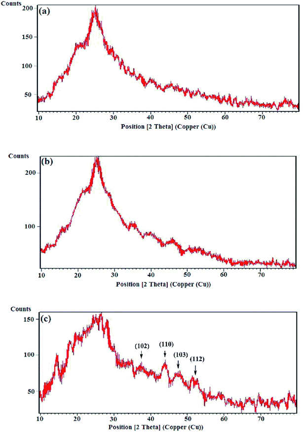 |
| | Fig. 4 X-ray diffraction patterns of (a) HPEc-g-PANi, (b) CdS@HPEc-g-PANi and (c) mCdS@HPEc-g-PANi. | |
3.2.2 SEM and EDX analyses. Fig. 5 shows the surface morphology features of the samples that were analyzed by SEM technique. The images have been shown in scale of 500 nm. The SEM image of the HPEc-g-PANi (Fig. 5a) illustrates that the particles are in form of cauliflower lumps while the incorporation of the CdS NPs caused a type of rod-shaped laminar nanostructure in the CdS@HPEc-g-PANi hybrid nanocomposite as shown in Fig. 5b. In fact this morphology represents that the PANi particles enclosed the CdS NPs and were grown as nanorod on their surface. This type of morphology is probably owing to this that the incorporation of the CdS NPs results in an aggregation of molecular network of the PANi on the surface of these NPs via the interchain linkages. These linkages are created through the coordination of Cd metal ions with nitrogen atoms of adjacent PANi chain. It can be perceived from the comparison of the SEM images that the modification of the CdS NPs led to the more smooth morphology as a form of intersecting networks in the mCdS@HPEc-g-PANi hybrid nanocomposite compared with the CdS@HPEc-g-PANi hybrid nanocomposite (Fig. 5c). This can be happened because of the better interactions and good compatibility of the mCdS NPs with the nanocomposite matrix. Indeed this difference of morphology is attributed to the synthetic method of nanocomposites, modification of nanoparticles and alignment of polymeric chains on the surface of the CdS NPs. In the mCdS@HPEc-g-PANi nanocomposite, the surface modification of the CdS nanoparticles (mCdS NPs) by the organic reagent, epichlorohydrin, resulted in their better dispersion in the nanocomposite matrix and a more smooth morphology. In the other hand in the modified nanocomposite (mCdS@HPEc-g-PANi), the polymeric chains are aligned on the surface of the mCdS NPs which leads to typical intersecting network morphology in the mCdS@HPEc-g-PANi. Whereas, direct coordination of reactive functional groups on the copolymer (e.g. nitrogen atoms in polyaniline segments) with bare CdS nanoparticles together with linear alignment of polyaniline segments owing to the π–π staking interaction of benzonoide and quinoide units changed the structure to a rod-shaped laminar morphology in the CdS@HPEc-g-PANi nanocomposite.
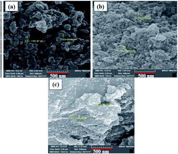 |
| | Fig. 5 SEM images of (a) HPEc-g-PANi, (b) CdS@HPEc-g-PANi and (c) mCdS@HPEc-g-PANi. | |
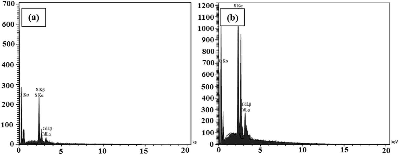
The elemental analyses of the samples composed of CdS were performed via the EDX analyses and the spectra are presented in Fig. 6a and b. The results indicate the presence of the main elements of C, O, N, Cd, and S in the CdS@HPEc-g-PANi and mCdS@HPEc-g-PANi hybrid nanocomposites. The weight ratios of C, O, N, Cd, S elements were also determined from the EDX analyses and the results are given in Table S1.†
 |
| | Fig. 6 The EDX spectra of CdS@HPEc-g-PANi (a) and mCdS@HPEc-g-PANi (b). | |
3.3 Thermal characterization
3.3.1 TGA analysis. The thermal stability of the samples was inspected via the TGA analyses and the thermograms are exhibited in Fig. S1a (in ESI†). The values of Tmax and weight loss percentages are summarized in Table S2 (in ESI†). With respect to the reported amounts of Tmax, the onset of degradation in the nanocomposites occurred at higher temperatures relative to HPEc-g-PANi copolymer. In addition the values of weight retention in the nanocomposites were slightly higher than that of HPEc-g-PANi copolymer. These results denote reasonable explanations for the higher thermal stability of the hybrid nanocomposites in the presence of CdS NPs.
3.3.2 DMTA analysis. Thermo-mechanical properties of the prepared samples were examined by the DMTA analyses and the results are shown as the curves of tan delta versus temperature in Fig. S1b (in ESI†) and approximate data of tanδ and glass transition temperature (Tg) in Table S3 (in ESI†). The curves exhibit some transitions and relaxations which can be correlated to the structure and morphology of the samples. The analyses were conducted over the temperature range of −20 °C to 350 °C. As shown, the hybrid nanocomposites exposed higher amounts of tanδ than the HPEc-g-PANi copolymer. This implies that the nanocomposites due to the presence of CdS NPs indicate more elasticity property than the HPEc-g-PANi copolymer. The CdS NPs via chelating interactions with nitrogen sites on the surface of PANi chain limit the segmental movements of the polymer chains and in this way lead to the reduction of energy dissipation and increase of elasticity property. It can be observed that the CdS@HPEc-g-PANi hybrid nanocomposite indicated higher Tg compared to the HPEc-g-PANi copolymer while the mCdS@HPEc-g-PANi hybrid nanocomposite showed slightly lower amount of Tg. It can be explained that the restriction in mobility of the polymer segments, reduction of free volume and consequently increase of rigidity of the system by in situ incorporation of CdS NPs resulted in emerging higher Tg in the CdS@HPEc-g-PANi hybrid nanocomposite. In contrast it is assumed that in the mCdS@HPEc-g-PANi hybrid nanocomposite probably due to better dispersion of CdS NPs and facility in slipping of the polymer chains on each other, Tg decreased in comparison with the HPEc-g-PANi copolymer.
3.4 UV/Vis spectroscopy
The UV/Vis absorbance spectra of the samples are shown in Fig. S2 (in ESI†). The UV absorption peak at about 250–300 nm is assigned to π–π* electron transition in benzenoid ring of PANi chain.26 The intensity of this band was increased in the CdS@HPEc-g-PANi compared to the HPEc-g-PANi copolymer probably due to the electrostatic interactions between conductive polymer chains and metal ions that can increase electron transfers in this way. The UV band at 300–440 nm can be assigned to the polaron–π* band transition demonstrating the PANi nanostructures grafted on HPEc chains.27 For the CdS@HPEc-g-PANi and mCdS@HPEc-g-PANi nanocomposites, a small absorption peak was observed at 440 nm while has not been revealed in the HPEc-g-PANi which can be corresponding to the absorption peak of CdS NPs.28 The intensity of this absorption peak was decreased slightly in mCdS@HPEc-g-PANi that can be related to the modification of the mCdS.
3.5 Electrical conductivity
The electrical conductivity measurements were carried out by four-probe method and the results are presented in Table 1. Regarding to the results, it can be perceived that the presence of the CdS NPs resulted in an increment in the conductivity of the nanocomposites compared with the HPEc-g-PANi copolymer. The electronic interactions between the electroactive metal centers and polymer backbone can enhance electron transport in the nanocomposites and as a result increase electrocatalytic activity.29 Moreover mCdS@HPEc-g-PANi hybrid nanocomposite showed an approximate six order increment in the electrical conductivity. It can be interpreted consistent with the better distribution of the CdS NPs in the matrix of the nanocomposite. From such a result it can be concluded that there is a relationship between morphology and electrical conductivity.30
Table 1 The conductivity results of the samples
| Sample |
σ (S cm−1) |
| HPEc-g-PANi |
0.47 × 10⁻² |
| CdS@HPEc-g-PANi |
0.84 × 10⁻² |
| mCdS@HPEc-g-PANi |
2.86 × 10⁻² |
3.6 Electrochemical studies
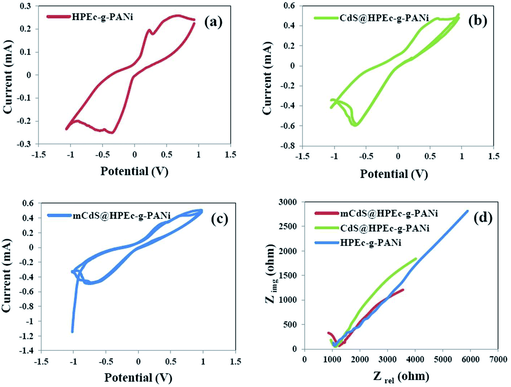
3.6.1 CV studies. The CV results were obtained in 0.05 M [Fe(CN)6]3−/4− solution in the presence of a little amount of KCl for ionization of the electrolyte solution. The experiments were run at different scan rates from 10 to 200 mV S−1 and the curves are displayed as current (mA) versus potential (V). For all the samples a common redox performance with well-defined quasi-reversible peaks was obtained at the lowest scan rate. To examine the effect of scan rate on the electrochemical behavior of the samples coated on electrode, the CV curves are indicated at different scan rates in Fig. S3 (in ESI†). With increasing scan rate, it is assumed that the electrode material would suffer from high diffusion resistance and extensive electrochemical polarization during the electrochemical process.31 This behavior was seen for all the samples and interprets that the electrochemical reaction is a low rate chemical-controlled process that due to getting away the oxidation and reduction peaks is a quasi-reversible reaction. The CV curves of the HPEc-g-PANi, CdS@HPEc-g-PANi and mCdS@HPEc-g-PANi samples at the scan rate of 10 mV S−1 are given in Fig. 7a–c. As can be observed from the curves, the currents corresponding to the oxidation peaks of the nanocomposites were higher than that of the HPEc-g-PANi copolymer. These results corroborate that the nanocomposites showed better CV performance compared with the HPEc-g-PANi copolymer that indicating the efficient presence and influence of the CdS NPs on electron-transfer process and consequently electrochemical performance. It seems that the electroactive CdS NPs via their direct band gap might influence on the electronic states of the PANi and enhance the electron transfer.
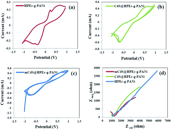 |
| | Fig. 7 CV curves of HPEc-g-PANi (a), CdS@HPEc-g-PANi (b) and mCdS@HPEc-g-PANi (c) and EIS plots of the prepared samples (d). | |
3.6.2 EIS studies. The EIS analyses were performed on the copper electrodes coated with the samples in 0.05 M [Fe(CN)6]3−/4− electrolyte in an OCP system. The results are presented as the plots of imaginary resistance (Zimg) as a function of real resistance (Zre) in Fig. 7d. The amounts of resistance, capacitance and internal charge transfer resistance (R3) obtained by fitting with an equivalent circuit for the samples are reported in Table 2. According to the results, the internal charge transfer resistance decreased in the presence of the CdS NPs that indicating the increase of charge transfer rate of the electrochemical system and consequently the better electrochemical performance of the hybrid nanocomposites compared to the HPEc-g-PANi copolymer. In addition among the nanocomposites, the nanocomposite composed of mCdS NPs showed lower electron transfer resistance than CdS@HPEc-g-PANi nanocomposite. It can be explained that the modification of the CdS NPs probably because of their better dispersion in the nanocomposite matrix and subsequently increase of surface area and efficient electrostatic interactions with PANi sites caused the facilitation in the electron transfer process and accordingly the reduction of the charge transfer resistance.
Table 2 The values of all the parameters obtained by fitting of EIS data with equivalent circuit
| Sample |
R1 (ohm) |
C2 (F) |
R2 (ohm) |
C3 (F) |
R3 (ohm) |
| mCdS@HPEc-g-PANi |
192.8 |
0.869 3 × 10⁻⁹ |
1035 |
1.26 × 10⁻³ |
7882 |
| CdS@HPEc-g-PANi |
9.767 |
0.104 7 × 10⁻⁹ |
1142 |
0.8214 × 10⁻³ |
10526 |
| HPEc-g-PANi |
500 |
0.527 8 × 10⁻⁹ |
610.9 |
7.66 × 10⁻³ |
41029 |
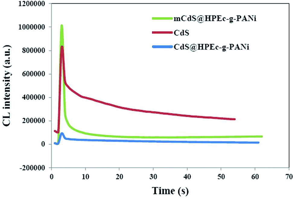
3.7 The CL spectroscopy
The CL measurements were conducted on 50 ppm concentration (based on CdS) of the predetermined amounts of the samples dispersed in 50 mL DMSO and the results are shown in Fig. 8. The CL spectra of the nanocomposites and synthesized bulk CdS were depicted. The results revealed that the CL intensity in the mCdS@HPEc-g-PANi hybrid nanocomposite was boosted by modification of CdS NPs compared to the bare CdS nanoparticles and unmodified hybrid nanocomposite (CdS@HPEc-g-PANi). This by reason of the better dispersion of CdS NPs in the mCdS@HPEc-g-PANi matrix than CdS@HPEc-g-PANi which leads to the creation of a synergistic effect between CdS NPs and PANi and augmentation of CL intensity. It is expected that with modification of CdS nanoparticles in the mCdS@HPEc-g-PANi nanocomposite, the band gap of the CdS NPs is more approached to the electronic sites of PANi and leads to promotion of electron transfer process in the composite which subsequently enhanced the CL intensity. As shown in the mechanism (Fig. 9), the LUMO and HOMO levels of PANi are combined with conduction band (CB) and valence band (VB) of CdS to form a heterojunction between PANi and CdS.32,33 Therefore by injection of electrons from electronic levels of PANi to bands of CdS NPs, formation of hydroxyl radicals is accelerated and therefore the intensity of chemiluminescence is increased. Summing up, the mCdS@HPEc-g-PANi nanocomposite with providing large surface area, uniformly distributed active sites and higher electrocatalytic activity for oxygen reduction reaction resulted a higher intensity in CL process.
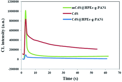 |
| | Fig. 8 The CL spectra of the prepared samples. | |
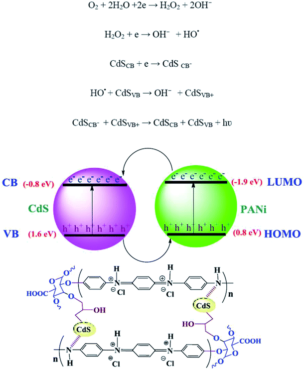 |
| | Fig. 9 The plausible proposed mechanism of CL process in the mCdS@HPEc-g-PANi nanocomposite. | |
4 Conclusion
Inorganic semiconductor nanoparticles caused by their unique opto-electronic properties have been the interesting topics in many studies in various fields of science and technology in the recent years. In this work, novel hybrid nanocomposites composed of PANi and HPEc with CdS NPs were prepared and characterized via different techniques including FTIR, XRD, SEM, EDX, UV/Vis, TGA and DMTA analyses. The four-probe electrical conductivity measurements unfolded a significant upturn in the electrical conductivity of the mCdS@HPEc-g-PANi nanocomposite and this result is consistent with the improvement in electrochemical and chemiluminescence performance for this sample. The scope of this work was study of electrochemical and chemiluminescence properties of the samples. The electrochemical measurements represented better electrochemical performance for the nanocomposites relative to the HPEc-g-PANi copolymer sample. The CdS NPs as electroactive centers augment electron transfer ability in the nanocomposites. The chemiluminescence experiments were performed on the hybrid nanocomposites and compared with the bulk CdS. The obtained spectra displayed that mCdS@HPEc-g-PANi had higher luminescence intensity than the CdS@HPEc-g-PANi nanocomposite owing to better dispersion of CdS NPs in the nanocomposite matrix. According to the obtained results, the good dispersed mCdS NPs due to increase of surface area improved the conductivity, electrochemical and chemiluminescence performance in mCdS@HPEc-g-PANi. This work discusses that electrochemical and chemiluminescence methods are effective tools to probe exploitation of the synthesized CdS-based nanocomposites as electrochemiluminescence for potential biosensor applications.
Conflicts of interest
In accordance with your policy for conflicts of interest, we declare that we don't have any conflict for the interests of this journal and agree with this submission and there are no conflicts to declare.
Acknowledgements
We are grateful from all honorable council from University of Mazandaran for supporting of this project. The work didn't have any financial support from funding organizations.
References
- J. Yang, Y. Liu, S. Liu, L. Li, C. Zhang and T. Liu, Mater. Chem. Front., 2017, 1, 251–268 RSC.
- D. Li, J. Huang and R. B. Kaner, Acc. Chem. Res., 2009, 42, 135–145 CrossRef CAS PubMed.
- B. K. Kuila, B. Nandan, M. Böhme, A. Janke and M. Stamm, Chem. Commun., 2009, 5749–5751 RSC.
- C. Dhand, M. Das, M. Datta and B. D. Malhotra, Biosens. Bioelectron., 2011, 26, 2811–2821 CrossRef CAS PubMed.
- S. Ameen, M. S. Akhtar, Y. S. Kim and H. S. Shin, Chem. Eng. J., 2012, 181, 806–812 CrossRef.
- J. Li, H. Xie, Y. Li, J. Liu and Z. Li, J. Power Sources, 2011, 196, 10775–10781 CrossRef CAS.
- M. Amelia, C. Lincheneau, S. Silvi and A. Credi, Chem. Soc. Rev., 2012, 41, 5728–5743 RSC.
- Y. Zhang, J. Zhu, X. Yu, J. Wei, L. Hu and S. Dai, Sol. Energy, 2012, 86, 964–971 CrossRef CAS.
- L. Li, Y. Chen, Q. Lu, J. Ji, Y. Shen, M. Xu, R. Fei, G. Yang, K. Zhang, J. R. Zhang and J. J. Zhu, Sci. Rep., 2013, 3, 1529 CrossRef PubMed.
- G. F. Jie, P. Liu and S. S. Zhang, Chem. Commun., 2012, 46, 1323–1325 RSC.
- P. S. Khiew, N. M. Huang, S. Radiman and M. S. Ahmad, Mater. Lett., 2004, 58, 516–521 CrossRef CAS.
- F. E. Osterloh, J. S. Martino, H. Hiramatsu and D. P. Hewitt, Nano Lett., 2003, 3, 125–129 CrossRef CAS.
- C. G. Wu, D. C. Degroot, H. O. Marcy, J. L. Schindler, C. R. Kannewurf, Y. J. Liu, W. Hirpo and M. G. Kanatzidis, Chem. Mater., 1996, 8, 1992–2004 CrossRef CAS.
- C. Querner, P. Reiss, J. Bleuse and A. Pron, J. Am. Chem. Soc., 2004, 126, 11574–11582 CrossRef CAS PubMed.
- S. Pethkar, R. C. Patil, J. A. Kher and K. Vijayamohanan, Thin Solid Films, 1999, 349, 105–109 CrossRef CAS.
- R. L. N. Chandrakanthi and M. A. Careem, Thin Solid Films, 2002, 417, 51–56 CrossRef CAS.
- D. Y. Godovsky, A. E. Varfolomeev, D. F. Zaretsky, R. N. Chandrakanthi, A. Kundig, C. Weder and W. Caseri, J. Mater. Chem., 2001, 11, 2465–2469 RSC.
- J. Fu, Z. Pang, J. Yang, F. Huang, Y. Cai and Q. Wei, Appl. Surf. Sci., 2015, 349, 35–42 CrossRef CAS.
- W. Wu, Y. Li, L. Yang, Y. Ma and X. Yan, Synth. Met., 2014, 193, 48–57 CrossRef CAS.
- H. Peng, G. Ma, W. Ying, A. Wang, H. Huang and Z. Lei, J. Power Sources, 2012, 211, 40–45 CrossRef CAS.
- J. Chen, W. Liu, C. M. Liu, T. Li, R. H. Liang and S. J. Luo, Crit. Rev. Food Sci. Nutr., 2015, 55, 1684–1698 CrossRef CAS PubMed.
- S. L. Sobhana, M. V. Devi, T. P. Sastry and A. B. Mandal, J. Nanopart. Res., 2011, 13, 1747–1757 CrossRef.
- M. Goswami, R. Ghosh and A. K. Meikap, 56th DAE Solid State Physics Symposium, India, Jun, 2012 Search PubMed.
- J. P. Pouget, M. E. Jozefowicz, A. J. Epstein, X. Tang and A. G. MacDiarmid, Macromolecules, 1991, 24, 779–789 CrossRef CAS.
- H. Zhang, X. Ma, Y. Ji, J. Xu and D. Yang, Chem. Phys. Lett., 2003, 377, 654–657 CrossRef CAS.
- N. D. Tissera, R. N. Wijesena, S. Rathnayake, R. M. Silva and K. M. Silva, Carbohydr. Polym., 2018, 186, 35–44 CrossRef CAS PubMed.
- N. R. Chiou and A. J. Epstein, Adv. Mater., 2005, 17, 1679–1683 CrossRef CAS.
- R. A. Devi, M. Latha, S. Velumani, G. Oza, P. Reyes-Figueroa, M. Rohini, I. G. Becerril-Juarez, J. H. Lee and J. Yi, J. Nanosci. Nanotechnol., 2015, 15, 8434–8439 CrossRef CAS PubMed.
- R. S. Norouzian and M. M. Lakouraj, Synth. Met., 2015, 203, 135–148 CrossRef CAS.
- P. Kannusamy and T. Sivalingam, Polym. Degrad. Stab., 2013, 98, 988–996 CrossRef CAS.
- V. H. Nguyen, L. Tang and J. J. Shim, Colloid Polym. Sci., 2013, 291, 2237–2243 CrossRef CAS.
- Y. C. Chen, T. C. Liu and Y. J. Hsu, ACS Appl. Mater. Interfaces, 2015, 7, 1616–1623 CrossRef CAS PubMed.
- Y. W. Su, W. H. Lin, Y. J. Hsu and K. H. Wei, Small, 2014, 10, 4427–4442 CrossRef CAS PubMed.
Footnote |
| † Electronic supplementary information (ESI) available. See DOI: 10.1039/c8ra10204j |
|
| This journal is © The Royal Society of Chemistry 2019 |
Click here to see how this site uses Cookies. View our privacy policy here. 
 Open Access Article
 This Open Access Article is licensed under a Creative Commons Attribution-Non Commercial 3.0 Unported Licence
 *a,
Mohsen Najafi Roudbarib and
Javad Chaichib
*a,
Mohsen Najafi Roudbarib and
Javad Chaichib