DOI:
10.1039/C8RA10155H
(Paper)
RSC Adv., 2019,
9, 4314-4324
An ultrasonic method for the synthesis, control and optimization of CdS/TiO2 core–shell nanocomposites
Received
11th December 2018
, Accepted 17th January 2019
First published on 4th February 2019
Abstract
In this study, an ultrasonic method was utilized in combination with microemulsion to synthesize CdS/TiO2 core–shell nanoparticles and control their particle size and ultimately optimize the influential parameters. Moreover, response surface methodology (RSM) was used to optimize the thickness of the shell. Herein, four parameters, i.e. temperature (67–79 °C), synthesis retention time (45–105 min), TiO2![[thin space (1/6-em)]](https://www.rsc.org/images/entities/char_2009.gif) :CdS ratio (1.5–7.5) and the power of ultrasound waves (37–53 watt), were optimized to synthesize nanoparticles with an average size of up to 10 nm. A correlation equation was introduced for the size range of 10–90 nm, which was then proven to have excellent predictions. To verify the proposed model, two different sets of combinations were selected to synthesize 10 nm composites, and consequently, nanocomposites with the sizes of 10.4 and 10.9 nm were successfully synthesized. The power of ultrasound waves and retention time had the most influence on the size of the particles. Further experiments proved that the optical absorption spectrum of the composite particles was extended to the visible region. Furthermore, the formation of CdS/TiO2 core–shell nanocomposites was confirmed by different characterization techniques including XRD, TEM, EDAX, UV-vis, FTIR and DLS.
:CdS ratio (1.5–7.5) and the power of ultrasound waves (37–53 watt), were optimized to synthesize nanoparticles with an average size of up to 10 nm. A correlation equation was introduced for the size range of 10–90 nm, which was then proven to have excellent predictions. To verify the proposed model, two different sets of combinations were selected to synthesize 10 nm composites, and consequently, nanocomposites with the sizes of 10.4 and 10.9 nm were successfully synthesized. The power of ultrasound waves and retention time had the most influence on the size of the particles. Further experiments proved that the optical absorption spectrum of the composite particles was extended to the visible region. Furthermore, the formation of CdS/TiO2 core–shell nanocomposites was confirmed by different characterization techniques including XRD, TEM, EDAX, UV-vis, FTIR and DLS.
1. Introduction
The importance of composite nanoparticles, especially core–shell materials, is undeniable not only in the field of chemistry but also in various other fields such as electronics, biomedical optics and catalysis. These materials are highly functional due to their ability to be produced with modified properties. Coating a core with a layer (shell) of different materials can be carried out for numerous purposes such as surface modification, stability, dispersibility, core release control, drug delivery and core consumption.1 Moreover, one of the most interesting features of core–shell composites, which has attracted the attention of scholars from different fields, is that they provide the possibility of combining the advantages of different materials.2,3 In the half past century, the advent and advancements in the synthesis of nanoparticles4 have led to a significant increase in their popularity; this is mainly due to their physical, chemical and optical features.5 Core–shell materials can also help compensate for the disadvantages of individual particles;2 one such material, which is widely used and synthesized in many different forms by researchers, is TiO2. TiO2 is a semiconductor that is mostly known in light science. This naturally safe material has fantastic photocatalytic activity in UV light, but has very low photocatalytic activity in visible light. Combining TiO2 with other semiconductors to extend the absorption of TiO2 to the visible region is an efficient way to tackle this problem. Several studies have been reported on the synthesis of core–shell and other forms of TiO2-based composites to enhance the photocatalytic and photocorrosion resistance during photodegradation and photocatalytic hydrogen production.6–10 The major problem in the synthesis of core–shell materials is the difficulty of coating the materials, especially inorganic components, on a small core. This is mainly due to the lack of proper coating methods as well as weak surface forces existing under normal conditions. The results achieved under normal conditions using conventional methods for the synthesis of core–shell particles, especially in the process of coupling semiconductors, may not be efficient since a quite long retention time (about one day or more) and high temperature (200–400 °C) are required for sufficient interfacial adhesion and crystallinity of both components.11–15 In this regard, one of the promising approaches that can overcome the aforementioned problems is the sonochemical method, in which ultrasound waves are utilized for the synthesis of different types of nanoparticles with a narrow size distribution under mild conditions.16–18 During irradiation of liquids with ultrasound, a phenomenon called cavitation takes place. The produced cavity serves as a mean to concentrate the diffused sound energy. In any acoustic field, once a microbubble experiences rapid growth, it can no longer efficiently absorb energy, and thus, the liquid will rush in, and the cavity will eventually implode.19,20 Once these grown bubbles collapse and implode, they act as a hotspot and generate energy, which can increase the local pressure and temperature to 500 atm and 5000 °C, respectively. Then, the liquid will cool down at the rate of 109 K s−1.20 These collapsing bubbles create a turbulence synthesis environment, an unusual mechanism for chemical reactions which need high level of energy to occur. The turbulent media and the consequent high velocity field can help with easier deposition of organic or inorganic materials on a small core as compared to the case of conventional methods. Due to these features, the use of ultrasonic waves has become a promising method for the synthesis of a wide range of materials ranging from inorganic/polymeric core–shell materials as a system modifier21 to inorganic/inorganic core–shell catalysts;2 although studies on the formation of CdS/TiO2 core–shell composites using ultrasound waves are quite rare, some studies on the formation of TiO2/CdS core–shell materials with a hexagonal phase and size in the range of 25–30 nm under a multi-bubble sonoluminescence (MBSL) condition are available.22 Note that not only the size of the particles obtained in this process is larger but also the complexity of the sonoluminescence reactor is a major drawback. In addition, synthesis of 0- and 1-dimensional mesoporous core–shell CdS/TiO2 with an average size of 20 nm through a sol–gel method was investigated.23 However, the sol–gel method and solvothermal-assisted synthesis, which have been used to prepare these CdS/TiO2 core–shells, are time-consuming;23 one of the most successful approaches to synthesize these particles is the sonochemical method, in which the complexity of the sonoluminescence reactor and the long duration of solvothermal synthesis are completely eliminated.2 Thus, it seems that the ultrasound approach would be a more promising way for the synthesis or at least for coating the nanoparticles. Use of ultrasonic waves with an experimental design approach, such as response surface methodology, can efficiently increase the performance of the synthesis; this is due to the possibility for the optimization of response, extrapolation of the results to unexamined data points and an accurate estimation of the extrapolated points. Among the RSM methods, the central composite design (CCD), which is a 2k factorial design with two variables and nc central point, is very famous. This method of design usually provides the best answers due to the reasonable distribution of points across the desired area.24 The aim of the present study was to synthesize CdS nanoparticles and then coat them with a TiO2 layer using an ultrasonic method. The targeted size of the final nanocomposite was 10 nm; thus, the influential parameters (i.e. temperature, time, TiO2:CdS ratio and power of sound beam) controlling the thickness of the shell were optimized accordingly using the RSM method, and a model was obtained. The model could also be used to synthesize CdS/TiO2 with different sizes. The other aspect of this study was to investigate the importance and impact of these parameters on the final composite size.
2. Materials and methods
2.1. Materials
Ethylenediamine, titanium tetra-isopropoxide (TTIP), CS2 and CdCl2·H2O were supplied by Merck Company and used without any further purification. Distilled water was used for all the syntheses and sample preparation steps.
2.2. Methods
2.2.1. Synthesis of the CdS nanoparticles. Typically, 1 mL of ethylenediamine was added to 50 mL water in a beaker at room temperature, and then, 0.3 mL of CS2 was added to complete the oil phase, which was irradiated for 20 min using ultrasound waves (TOMY, UD 201, acoustic power 45 W with digital water bath temperature controller) at 40 °C until the solution became clear. Then, an aqueous solution of hydrated cadmium chloride (0.3 g dissolved in 15 mL of distilled water) was added to the beaker as an aqueous phase, and the entire solution was sonicated for about 15 min without changing the temperature. After the mixing process, the temperature was increased to about 75 °C for 10 min for the nucleation of the CdS nanoparticles, and then, it was kept constant for another 30 minutes.25 The CdS nanoparticles were obtained via centrifugation, and then, the precipitate was separated, washed with distilled water and ethanol, and dried at room temperature. Finally, 0.05 g of dried CdS particles was added to 20 mL distilled water followed by sonication for 5 minutes to achieve uniform dispersion. Then, 5 mL of this solution was characterized using dynamic light scattering to measure the particle size and size distribution.
2.2.2. Synthesis of core–shell nanoparticles. To coat the CdS nanoparticles with TiO2, titanium isopropoxide (TTIP) was added drop-wise to the solution in an ultrasonic medium. The final product was separated by centrifugation (5000 rpm for 20 minutes), washed with absolute ethanol and distilled water, and dried in an oven at 70 °C for 1 hour. Further, the parameters, i.e., time, temperature, TiO2:CdS ratio and power of the sonic beams, that affect the thickness of the shell were optimized according to the statistical experimental design. The goal of this optimization was to achieve core–shell structures with desirable size.26
2.3. Characterization of the nanocomposite
The structure and morphology of the products were investigated using X-ray diffraction (Bruker D8 Advanced), energy dispersive X-ray spectroscopy (Philips XL 30S FEG), transmission electron microscopy (Philips, CM120 Bio-TWIN), dynamic light scattering (HORIBA – LB550), and FTIR spectroscopy (Perkin Elmer – Spectrum RX I); moreover, ultraviolet-visible spectroscopy (Perkin Elmer, Lambda 850) was employed to study the products from a photocatalytic point of view.
2.4. Experiment design
Analysis of experimental data and the suggested experiments were carried out by Design-expert® version 7.0. An RSM based on the central composite design (CCD) was applied to determine the number and conditions of the experiments needed to develop a model. Each numerical factor varied at five levels. Moreover, thirty experiments were suggested by the CCD method for the optimization of the influential parameters. In the suggested sets of experiments, four independent variables (time, temperature, molar ratio of TiO2 to CdS and power of sonic beams) were used in the RSM. Each variable was found to be within the range suggested in previous studies.2,11,13 In addition, to improve the synthesis model, a level higher and lower than the suggested levels were selected and investigated. Table 1 shows the parameters used in the RSM design using the CCD method. The units and the range of change for each parameter are presented. (The range of change appears in terms of ± alpha.)
Table 1 Core–shell and CCD parametersa
| |
Name |
Unit |
−1 Level |
+1 Level |
− Alpha |
+ Alpha |
| Alpha: 2, replicates of factorial points: 1, replicates of axial points: 1, center point: 6. |
| A |
Temperature |
°C |
70 |
76 |
67 |
79 |
| B |
Time |
min |
60 |
90 |
45 |
105 |
| C |
TiO2/CdS |
Molar ratio |
3 |
6 |
1.5 |
7.5 |
| D |
Wave power |
Watt |
41 |
49 |
37 |
53 |
3. Results and discussion
3.1. Core size analysis
Fig. 1 shows the DLS pattern of the synthesized CdS core. The pattern indicates a narrow size distribution of the synthesized CdS nanoparticles with an average size of 8.7 nm. As shown in the pattern, the particle size varied between 3.5 and 10.5 nm, and the most intense peak (about 26%) occurred at 9 nm.
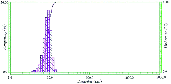 |
| | Fig. 1 DLS pattern of the CdS nanoparticles. | |
3.2. Statistical analysis
The response used in the model was the size of the synthesized nanocomposite in each experiment. The size of each composite was measured using the DLS method. Table 2 represents the influential parameters, the suggested combinations and the output results. (*Indicates center point experiments.)
Table 2 Output data for the suggested experimentsa
| Run |
Temperature (°C) |
Time (min) |
Power (watt) |
Ratio (molar ratio) |
Size (nm) |
Run |
Temperature (°C) |
Time (min) |
Power (watt) |
Ratio (molar ratio) |
Size (nm) |
| Statistical analysis of the output data obtained from the experiments was performed by Design Expert® version 7.0.0. |
| 1 |
73.00 |
75.00 |
45.00 |
4.50 |
16.63* |
16 |
73.00 |
75.00 |
45.00 |
4.50 |
17.42* |
| 2 |
70.00 |
90.00 |
41.00 |
6.00 |
44.11 |
17 |
73.00 |
75.00 |
37.00 |
4.50 |
91.62 |
| 3 |
73.00 |
75.00 |
45.00 |
4.50 |
17.24* |
18 |
73.00 |
75.00 |
45.00 |
4.50 |
16.41* |
| 4 |
70.00 |
90.00 |
49.00 |
6.00 |
22.7 |
19 |
76.00 |
60.00 |
41.00 |
6.00 |
33.25 |
| 5 |
70.00 |
60.00 |
41.00 |
6.00 |
29.41 |
20 |
76.00 |
60.00 |
49.00 |
3.00 |
10.12 |
| 6 |
73.00 |
75.00 |
45.00 |
7.50 |
15.93 |
21 |
76.00 |
90.00 |
49.00 |
6.00 |
16.91 |
| 7 |
70.00 |
60.00 |
49.00 |
3.00 |
11.57 |
22 |
79.00 |
75.00 |
45.00 |
4.50 |
18.97 |
| 8 |
73.00 |
75.00 |
53.00 |
4.50 |
20.13 |
23 |
73.00 |
75.00 |
45.00 |
4.50 |
17.05* |
| 9 |
70.00 |
60.00 |
41.00 |
3.00 |
23.65 |
24 |
73.00 |
45.00 |
45.00 |
4.50 |
15.19 |
| 10 |
76.00 |
60.00 |
41.00 |
3.00 |
24.62 |
25 |
67.00 |
75.00 |
45.00 |
4.50 |
19.19 |
| 11 |
70.00 |
90.00 |
41.00 |
3.00 |
42.12 |
26 |
76.00 |
90.00 |
41.00 |
3.00 |
37.8 |
| 12 |
70.00 |
90.00 |
49.00 |
3.00 |
23.85 |
27 |
73.00 |
75.00 |
45.00 |
4.50 |
15.94* |
| 13 |
76.00 |
90.00 |
41.00 |
6.00 |
49.52 |
28 |
76.00 |
60.00 |
49.00 |
6.00 |
17.74 |
| 14 |
70.00 |
60.00 |
49.00 |
6.00 |
18.54 |
29 |
73.00 |
75.00 |
45.00 |
1.50 |
11.63 |
| 15 |
76.00 |
90.00 |
49.00 |
3.00 |
21.14 |
30 |
73.00 |
105.00 |
45.00 |
4.50 |
49.65 |
To assess the statistical and mathematical adequacy of the proposed model, a plot comparing the predicted response values of the model with the experimental data was generated (Fig. 2), which showed a good agreement between the values predicted by the model and the observed values. Based on the experimental data listed in Table 2, an empirical equation was derived as follows:
| | |
S−0.14 = −0.72235 − 0.015873 × Te − 3.24399 × 10⁻³ × Ti − 0.035904 × T:C + 0.090528 × WP + 3.66045 × 10⁻⁴ × Te × WP + 4.01792 × 10⁻⁴ × Ti × Tc − 1.21566 × 10⁻³ × WP2
| (1) |
where
S, Te, Ti, T
:
C and WP represent the core–shell size, temperature, time, TiO
2:
CdS ratio and the power of waves, respectively.
| | |
S−0.14 = 0.66 + 1.793 × 10⁻³ × A − 0.022 × B − 8.654 × 10⁻³ × C + 0.031 × D + 4.393 × 10⁻³ × A × D + 9.040 × 10⁻³ × B × C − 0.019 × D2
| (2) |
where
S,
A,
B,
C and
D represent the core–shell size, temperature, time, TiO
2:
CdS ratio and the power of waves, respectively.
Eqn (2) is the coded form of
eqn (1). In this equation, the positive values indicate a favourable effect of the parameter on the response, whereas the negative values represent an antagonistic effect on the response (an inverse relationship); moreover, the magnitude of these numbers shows the extent of the impact of each factor.
27,28 As
eqn (2) indicates, the positive sign for
A and
D allow the particles to have a smaller size. In addition, the magnitude of coefficient indicates that the impact of
D is far more than that of
A. On the other hand, the negative signs for
B and
C indicate an antagonistic effect
i.e. the higher these parameters, the greater the particle growth. In this case, the retention time has more impact on the particle size than the precursor ratio. Statistical analysis (ANOVA) proved that the model was significant as the
F value for the model was 24.95 and the corresponding
p value was <0.0001. This would mean that there was only a 0.01% chance that this
F-value for the model could occur due to noise. The lack of fit
F value of 0.07 was not considered significant as the
p value was 1.000. For a model to have a successful prediction, the lack of fit should not be significant. Moreover, the adjusted
R-squared value is very close to the corresponding
R-squared value; this further confirms the adaptability of this model.
29 The predicted
R-squared of 0.8909 is in reasonable agreement with the adjusted
R-squared of 0.9326. Adequate precision is determined by the signal to noise ratio. A ratio greater than 4 is desirable, and the obtained ratio has been found to be 22.848, which indicates an adequate signal and also proves that this model can be used to navigate the design space.
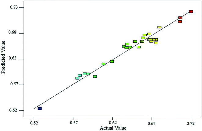 |
| | Fig. 2 Relationship between the predicted and experimental sizes of the synthesized nanocomposite. | |
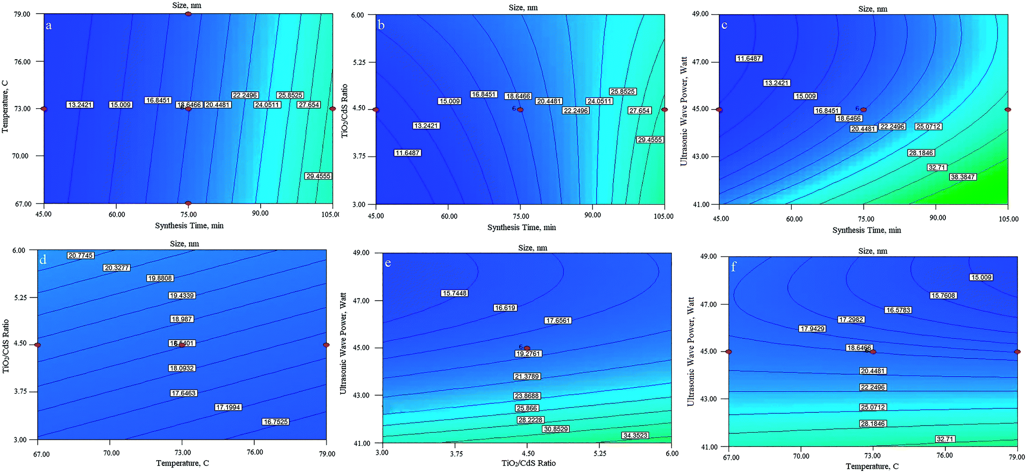
3.3. Effect of the factors affecting the particle size
The perturbation diagram, as shown in Fig. 3, is useful for predicting the impact of different parameters on the particle size of the nanocomposite.
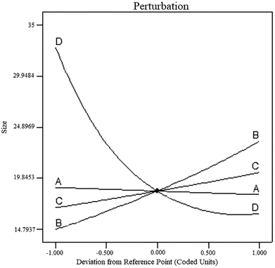 |
| | Fig. 3 Perturbation diagram of the model. | |
Line (A) from left to right indicates an increase in temperature, which leads to a reduction in the size of the synthesized particles. Temperature shows the smallest effect on the particle size. By increasing the time of synthesis, the residual TiO2 particles are allowed to hit and join the formed shell; this increases the shell thickness, and consequently, the size of the core–shell is increased, as indicated by Line (B). Moreover, an increase in the ratio of the precursors led to growth in the size of the synthesized particles. Line (C) indicates the increase in TiO2 to CdS precursor ratio. As the amount of TiO2 particles in the mixture increased, the probability of formation of a denser and thicker shell also increased due to higher amounts of the TiO2 precursor (TTIP) than those of the CdS precursors (CS2 and CdCl2·H2O). This phenomenon was almost similar to that of retention time, but the influence of retention time was far more significant than that of the ratio of components. As the power of the ultrasound waves increases, the level of turbulence in the system will also increase, and the particles will collide each other with higher momentum and the chances for the formation of agglomerate particles will definitely diminish. This phenomenon is shown by curve (D), and as it can be seen, by increasing the power of the ultrasound waves, the particle size of the final product can be decreased. The interactions between parameters were studied using the contour plots shown in Fig. 4. As the perturbation diagram indicates, temperature has the least influence on the size as compared to the other factors. In fact, if one of the other factors remained constant, a change in temperature could not alter the size of particles. This behavior can be observed in Fig. 4a, d and f. The most important interaction was between the synthesis retention time and the power of sonic waves, which acted in opposite directions. Upon increasing the power of beams, the size of the particles reduced, and an increase in retention time led to an increase in the particle size. Note that the synthesis of fine particles requires adequate power of ultrasound. However, the contours in Fig. 4c indicate that after a specific retention time, any further increase in the power of sonic waves is ineffective since it can no longer overcome the influence of retention time, and thus, the particle size will increase. The interaction between the sonic waves and the precursor ratio can be regarded the same as the interaction between the synthesis retention time and the power of sonic waves. Their influence is fairly smoother as compared to that of the retention time; however, it cannot be ignored. For example, Fig. 4e indicates that at the center points of temperature and retention time, TiO2:CdS ratios greater than 5.3 cannot lead to particles smaller than 17 nm. The last interaction studied was between the retention time and the precursor ratio, and since both these parameters act in favor of the increase in the particle size, their interaction led to a constructive interference, and ultimately, the final size of the particles increased.
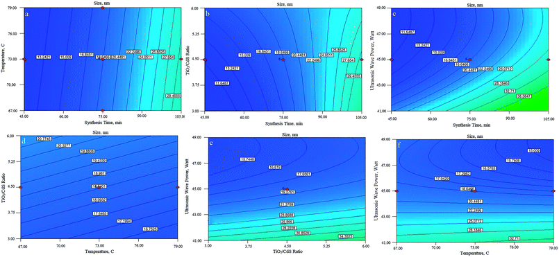 |
| | Fig. 4 Contour plots of the different parameters affecting the particle size. | |
3.4. Optimization of core–shell
As the goal of this study was to achieve a size of 10 nm, the model was optimized accordingly. Thus, the size of the particle was intentionally maintained constant at 10 nm, whereas the other parameters were changed within their operational range except for the TiO2:CdS ratio. This ratio was purposely minimized due to financial consideration and the high cost of the initial precursors. Table 3 shows the optimization parameters, their goal and importance. As shown, the optimization process suggested the relationships between parameters for achieving a 10 nm composite particle, and the ratio between precursors is minimal.
Table 3 Optimization factors, goals, limits and importance of each parameter
| Name |
Goal |
Lower limit |
Upper limit |
Lower weight |
Upper weight |
Importance |
| Temperature |
Is in range |
67 |
79 |
0.231101 |
0.301407 |
5 |
| Time |
Is in range |
45 |
105 |
1 |
0.265826 |
3 |
| TiO2/CdS |
Minimize |
1.5 |
7.5 |
1 |
0.1 |
5 |
| Wave power |
Is in range |
37 |
51 |
1 |
1 |
3 |
| Size |
Is 10 nm |
11.57 |
91.62 |
0.1 |
0.265826 |
5 |
Some of these relations are shown in Table 4. To assess the model, two different combinations with different amounts of TiO2:CdS precursors were selected from the table: 2.97 and 4.87 for composite A and composite B, respectively.
Table 4 A few combinations of the synthesis parameters for synthesizing a 10 nm composite
| Solutions number |
Temperature (°C) |
Time (min) |
TiO2:CdS (molar ratio) |
Wave power (watt) |
Size (nm) |
Desirability |
Result |
| 1 |
70.26 |
46.92 |
3.73 |
48.82 |
10.001 |
0.961 |
|
| 2 |
67.72 |
49.66 |
2.97 |
49.37 |
10 |
0.951 |
Selected (CA) |
| 3 |
77.46 |
64.41 |
1.94 |
47.68 |
10.001 |
0.945 |
|
| 4 |
72.13 |
56.07 |
1.99 |
45.00 |
10.001 |
0.918 |
|
| 5 |
78.95 |
45.32 |
4.87 |
49.15 |
9.999 |
0.914 |
Selected (CB) |
3.5 Characterization of the synthesized core–shell composite
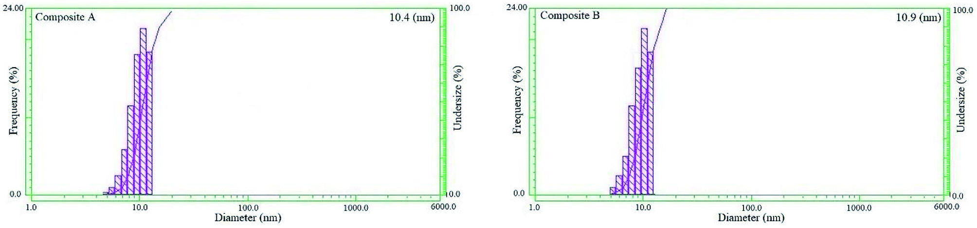
Fig. 5 shows the DLS patterns representing the size distribution of the CdS/TiO2 particles. As the plots shows, particles of both composites have narrow distribution with the average sizes of 10.4 and 10.9 nm. The actual data shows only 0.4 and 0.9 nm difference as compared to the model prediction.
 |
| | Fig. 5 DLS analysis of the nanocomposites. | |
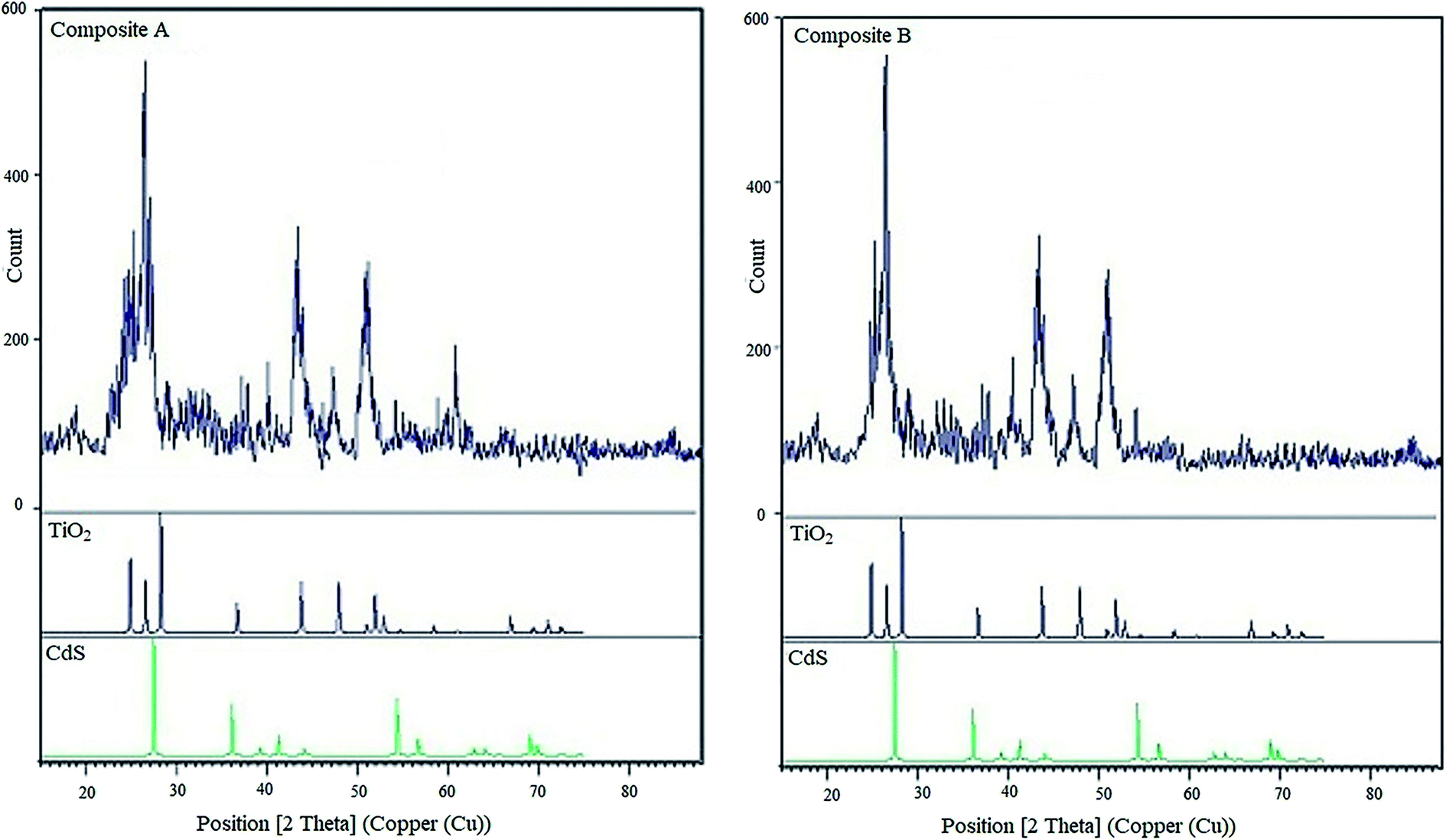
Fig. 6 shows the XRD patterns of composite A, composite B, TiO2 and CdS (individual component patterns are obtained from the HighScore Plus database version 2013). The XRD patterns reveal that the TiO2 nanoparticles are in anatase phase with intense peaks at 2θ = 24.9°, 26.5°, 28.2°, 36.8°, 44°, and 48.1°, and the CdS nanoparticles have intense peaks at 2θ = 27.5°, 36.1°, 54.5°, and 69.1°. The relatively narrow XRD peaks of both composites show that the particle sizes are in nano scale, and the thickness of the TiO2 shell formed on CdS nanoparticles is less. A comparison between the X-ray diffraction patterns of composites A and B revealed that the lower peak breadth of composite A represented a smaller size of the product, and consequently, a shell containing less amount of deposited TiO2 was obtained on the CdS core.
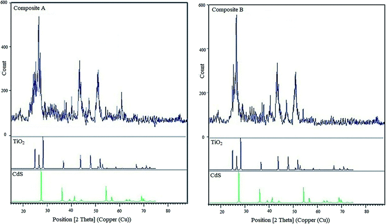 |
| | Fig. 6 XRD patterns of composite A, composite B and the individual patterns of TiO2 and CdS. | |
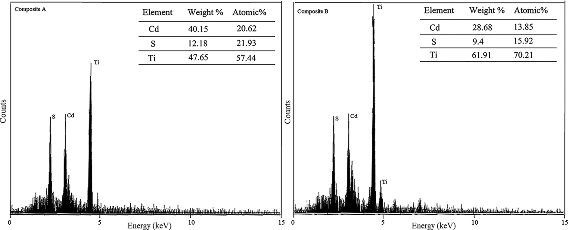
Chemical composition analysis by the EDAX method showed moderate to high purity for each component in both the CA and CB composites. The analysis also revealed that the atomic percentages of Cd, S and Ti were 20.62, 21.93 and 57.44 in the composite A and 13.85, 15.92 and 70.21 in the composite B, respectively. This means that the atomic ratios between Cd and S are almost 1:1 in both composites, which indicates that about 21.2% and 14.9% of composite A and B have been made by the CdS particles, respectively. Consequently, the ratio of TiO2:Cds in composites A and B would be 2.71:1 and 4.71:1, respectively (2.97:1 and 4.87:1, as listed in Table 2). Fig. 7 shows the EDAX patterns of both composites A and B.
 |
| | Fig. 7 EDAX patterns of composites A and B. | |
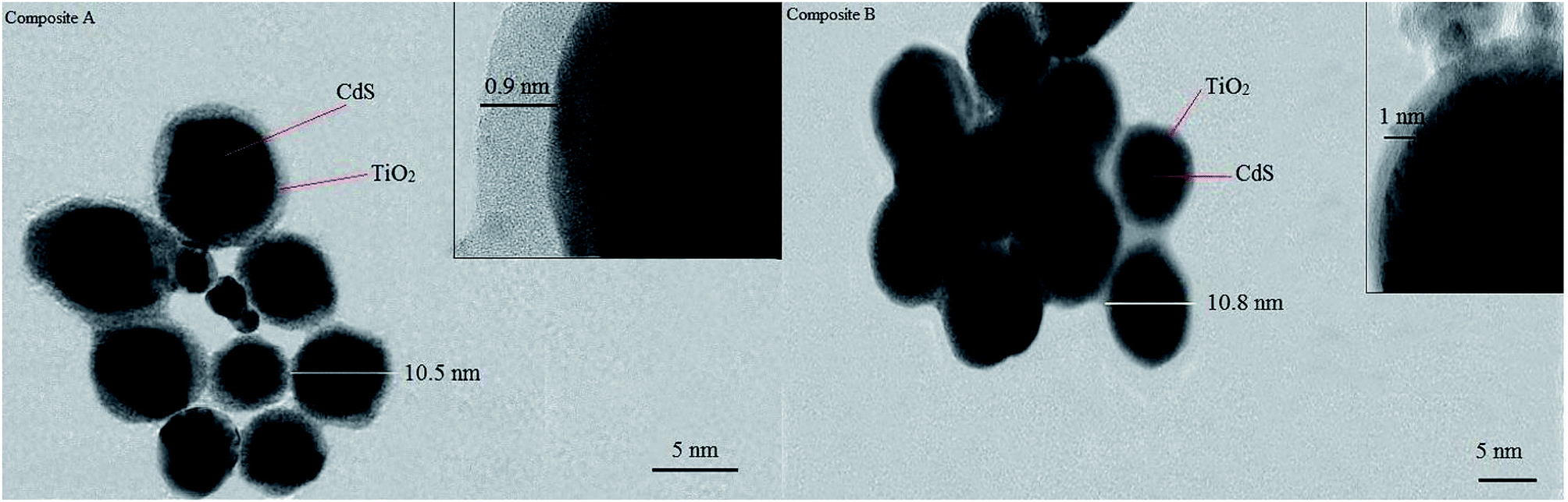
The efficiency of encapsulation of both composites, actual size of individual composite and shapes of the cores and shells were investigated by TEM. The images clearly demonstrated that a nano-sized layer of titanium oxide (0.9 and 1 nm respectively for composite A & B) fully enclosed the 9 nm CdS core. The spherical shape of the cores is speculated to have arisen due to the high-velocity synthesis field. Cavitation phenomena and the intense change in local temperature and pressure lead to the development of a high velocity field. In this field, particles collide each other with a great momentum. This great momentum leads the particles to reach their most stable shape in a three-dimensional medium. In a fluid medium, sphere is the most stable shape, and our TEM images prove this fact. Fig. 8 shows the TEM images of both the composite A & the composite B particles.
 |
| | Fig. 8 TEM images of the nanocomposites A and B. | |
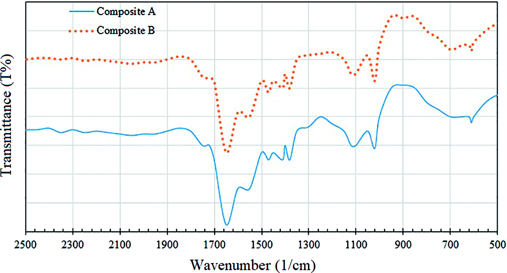
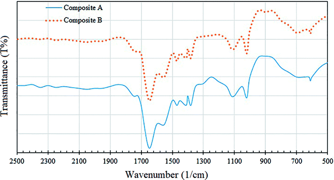
Fig. 9 illustrates the FTIR spectra of the composites A and B over 500–2500 cm−1. The reference charts indicate that the peak in the region 400–600 cm−1 is due to the transverse optical active vibration of the Ti–O bonds, whereas the peak in the region 700–950 cm−1 is due to the longitudinal optical (LO) vibrational mode.30 The sharp peak at 1400 cm−1 can be recognized to be due to the lattice vibrations of TiO2.31 In addition, a binding vibration associated with Ti–OH can be seen as an absorption band at 1627 cm−1.30 For CdS, the reference charts indicate peaks at 619 and 659 cm−1 due to Cd–S stretching.32 Moreover, the peaks at 1391 and 1630 cm−1 indicate the lattice vibrations of CdS.30 As shown in Fig. 9, the peaks in the 500–700 cm−1 region indicate an overlap between TiO2 and CdS, and the peaks at 1380, 1410 and 1650 cm−1 clearly reveal that the CdS molecules are attached to TiO2.
 |
| | Fig. 9 FTIR spectra of the nanocomposites A and B. | |
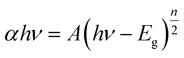
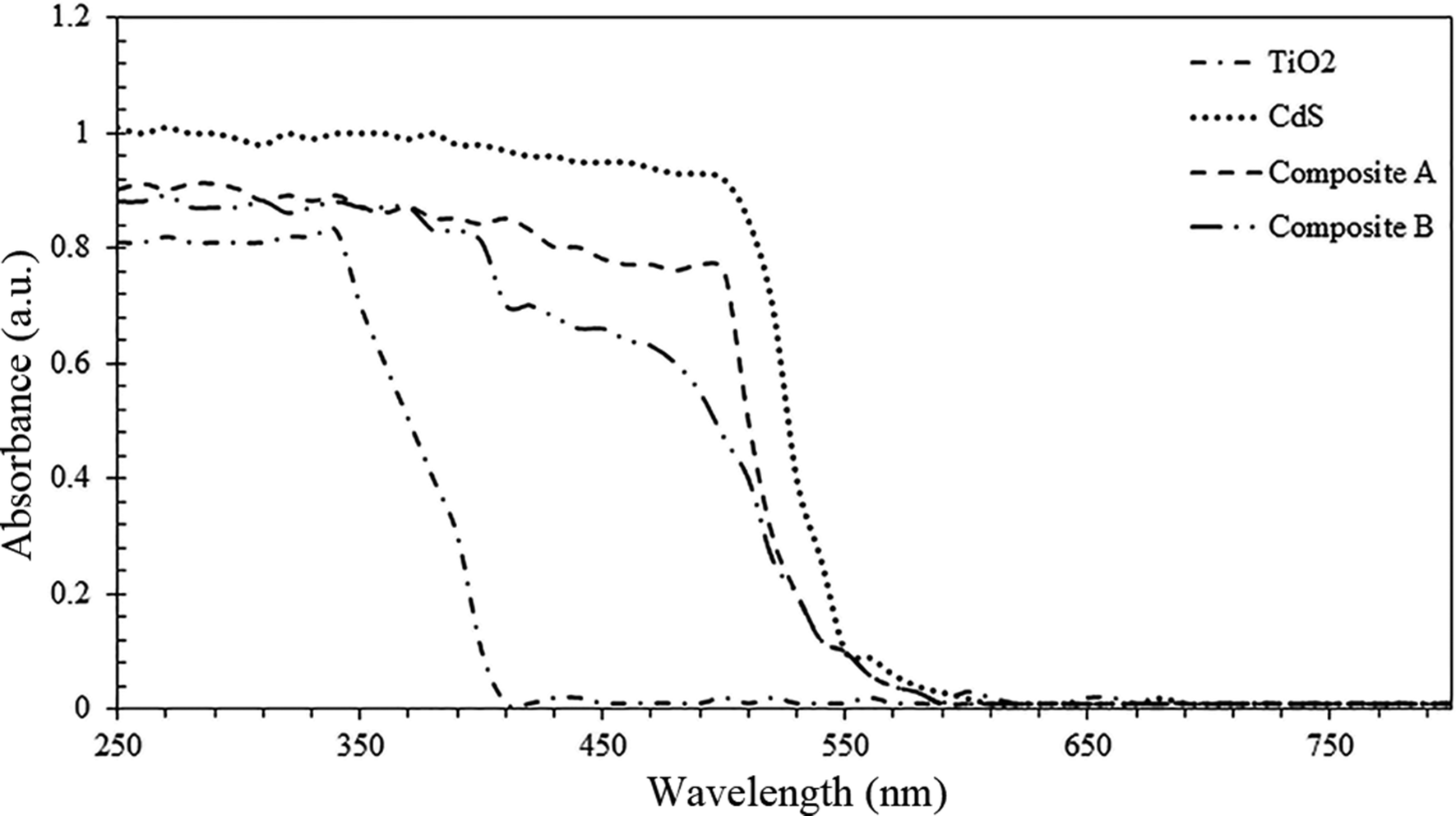
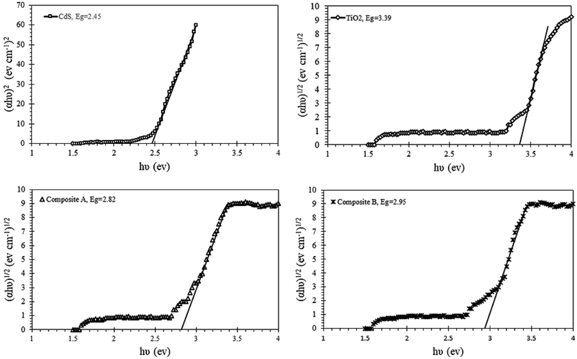
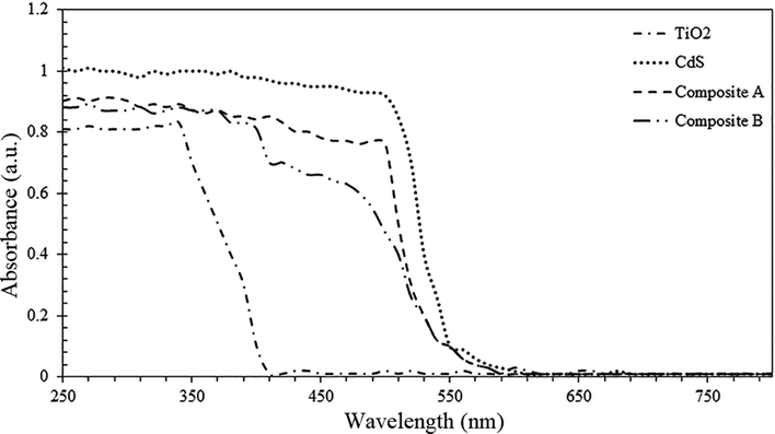
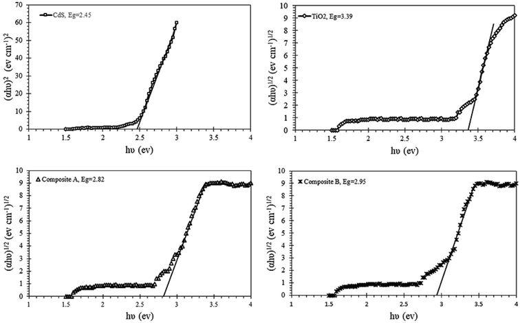
In photocatalysis research, UV-vis absorption spectroscopy is one of the most important characteristic tests to monitor the band gap shifts. Fig. 10 represents the UV-vis absorption spectra of both composites as well as pure components. As the spectra indicates, the absorption of composite B is in a lower wavelength region as compared to that of composite A. This phenomenon is due to the higher ratio of TiO2:CdS and the thicker shell of composite B. The band gap plots for these components are illustrated in Fig. 11. Pure TiO2 and CdS nanoparticles show the band gap energies of 3.39 and 2.45 eV, whereas the composite A & composite B show the band gap energies of 2.82 and 2.95 eV, respectively. Participation of TiO2 and CdS in the core–shell system has led to a red shift in the absorption spectra of pure TiO2, and the optical absorption has extended to the visible region as compared to that of the pure TiO2 particles. Red shift of the spectrum is a typical characteristic of core–shell nanocrystals with higher band gap shells due to reduction in the surface defects of the core.33 The Eg or band gap of samples has been determined by plotting the following equation (eqn (3))34 and extrapolating the linear portion, which intercepts the energy axis hν.
| |
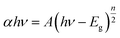 | (3) |
where
α is the absorption coefficient,
h is the Planck's constant,
ν is the light frequency,
n is a proportionality constant, and
A and
Eg are the constant and the band gap of the nanoparticle, respectively. The exponent ‘
n’ is determined by the transition of semiconductor, for example, a direct transition for zinc ferrite and cadmium sulfide (
n = 1),
2,34,35 and an indirect transition for TiO
2 (
n = 4).
34 As shown in
Fig. 11, the indirect measurement of optical transition shows a reduction in the band gap for both composites with respect to pure TiO
2. Moreover, the composite A shows more reduction in energy due to a lower ratio of TiO
2/CdS.
 |
| | Fig. 10 UV-vis absorption spectra of both composites and pure components. | |
 |
| | Fig. 11 Band gap of the composites and pure semiconductors. | |
3.6. Nucleation and growth mechanism
The formation of CdS nanoparticles is based on the reaction between ethylenediamine, hydrated cadmium chloride and carbon disulfide present in the aqueous phase and oil phase. The chemical and physical effects of the ultrasound arise from acoustic cavitation, which is responsible for the mixed phase reactions and mass transfer between the two phases.2,25,36 In the absence of surfactants, cavitation plays the same role as microemulsion in mixing the aqueous phase and oil phase. On adding cadmium ions to the oil–water interface of the solution, the CdS nanoparticles are formed, and their formation may be attributed to the following sequence of reactions:37 the turbulent flow aids ethylenediamine in attacking the C–S bond of CS2; upon polymerization of the product from this reaction, H2S gas is produced and reacts with cadmium ions in the oil–water interface of the solution. Eventually, the polymerized molecules produced in the reaction may bridge the oil droplets and water at the CS2–water surface to prevent agglomeration of the droplets.25 Eqn (4a) and (b) show the polymerization reaction of the sulfur source CS2 to produce H2S gas for the synthesis of CdS.| | |
C2H8N2 + CS2 → C3H8N2S2
| (4a) |
| | |
n(C3H8N2S2) → (–HN–CH2–CH2–NH–SC)n + H2S
| (4b) |
After synthesis of the core, TTIP was added drop-wise to the mixture in the presence of ultrasound waves to increase the rate of hydrolysis of TTIP and form the TiO2 shell.22 During the formation of the shell, cavitation and its physical and chemical effects are responsible for the deposition of a uniform layer of TiO2 on the CdS nanoparticles. The hydrolysis reaction of TTIP is a simple but efficient way to produce the TiO2 particles. Titanium isopropoxide hydrolyses in the presence of water as per the following reaction:
| | |
Ti(OC3H7)4 + 2H2O → TiO2 + 4C3H7OH
| (5) |
The 1-propanol produced herein is miscible in water, and hence, the TiO2 particles are formed.38 Cavitation can also remove contaminants from the particle surface; this causes the formation of uniform clusters.39 Highly turbulent flow can also drive the nanoparticles towards each other at very high velocity to form the core–shell particles, especially in spherical shape.40
4. Conclusion
In this study, CdS particles and CdS/TiO2 core–shell nanocomposite were successfully synthesized under a mild condition through microemulsion and ultrasonic synthesis methods, respectively. To control the thickness of the TiO2 coating, influential parameters that affect the shell were optimized by means of response surface methodology, and the best combination ratio of these parameters was obtained. The optimization process was aimed to minimize the ratio of TiO2 to CdS to yield a 10 nm composite, whereas the other factors were changed freely within their operational range. Finally, it was concluded that the power of ultrasound waves had the most influence on the size of the particles. The second most influential parameters were the retention time of synthesis and precursor proportion, whereas temperature was found to have the least impact on particle size. The interaction between sonic waves and synthesis retention time revealed that the retention time must be kept less than 50 minutes to obtain fine particles through this synthesis method. The thickness of the TiO2 shell could be regulated (from 1.4 nm to 41.4 nm) using the proposed model. The sizes of CdS and composite nanoparticles were investigated via DLS and TEM analyses, respectively. TEM images also revealed complete encapsulation of the CdS particles by the TiO2 shell, which was in a spherical shape with acceptable dispersion of particles. Due to coupling with CdS particles, a red shift in the absorption spectra of CdS/TiO2 was observed via UV-vis analysis as compared to the case of pure TiO2. There are many advantages of applying the present method. First, it is a low-temperature and short-duration method of synthesis. Moreover, the spherical shape of particles, controlled shell depth and acceptable dispersion of particles could be achieved in the absence of surfactants.
Conflicts of interest
This project has no financial and personal relation with other people and organizations. The corresponding author paid all costs of the project.
References
- D. Mangalaraj and D. N. Devi, Recent Trends in Materials Science and Applications, 2017, vol. 189, pp. 9–17 Search PubMed.
- N. Ghows and M. H. Entezari, Ultrason. Sonochem., 2012, 19, 1070–1078 CrossRef CAS PubMed.
- J. Zhang, J. Gao, X. Sun, Z. Peng and J. Diao, Iran. Polym. J., 2007, 16, 39–46 CAS.
- A. Simchi, E. Tamjid, F. Pishbin and A. R. Boccaccini, Nanomedicine, 2011, 7, 22–39 CrossRef CAS PubMed.
- M. Sahooli, S. Sabbaghi and R. Saboori, Mater. Lett., 2012, 81, 169–172 CrossRef CAS.
- H. H. El-Maghrabi, A. A. Al-Kahlawy, A. A. Nada and T. Zaki, J. Hazard. Mater., 2018, 360, 250–256 CrossRef CAS PubMed.
- A. A. Nada, H. R. Tantawy, M. A. Elsayed, M. Bechelany and M. E. Elmowafy, Solid State Sci., 2018, 78, 116–125 CrossRef CAS.
- H. H. El-Maghrabi, A. A. Nada, K. R. Diab, A. M. Youssef, A. Hamdy, S. Roualdes and S. A. El-Wahab, J. Photochem. Photobiol., A, 2018, 365, 86–93 CrossRef CAS.
- A. A. Nada, M. F. Bekheet, S. Roualdes, A. Gurlo and A. Ayral, J. Mol. Liq., 2018, 274, 505–515 CrossRef.
- M. A. Deyab, A. A. Nada and A. Hamdy, Prog. Org. Coat., 2017, 105, 245–251 CrossRef CAS.
- Y. Liu, F. Xin, F. Wang, S. Luo and X. Yin, J. Alloys Compd., 2010, 498, 179–184 CrossRef CAS.
- R. Brahimi, Y. Bessekhouad, A. Bouguelia and M. Trari, Catal. Today, 2007, 112, 62–65 CrossRef.
- Y. Bessekhouad, D. Robert and J. V. Weber, J. Photochem. Photobiol., A, 2004, 163, 569–580 CrossRef CAS.
- S. C. Lo, C. F. Lin, C. H. Wub and P. H. Hsieh, J. Hazard. Mater., 2004, 114, 183–190 CrossRef CAS PubMed.
- R. Brahimi, Y. Bessekhouad, A. Bouguelia and M. Trari, J. Photochem. Photobiol., A, 2008, 194, 173–180 CrossRef CAS.
- J. P. Cheng, R. Ma, D. Shi, F. Liu and X. B. Zhang, Ultrason. Sonochem., 2011, 18, 1038–1042 CrossRef CAS PubMed.
- L. M. Cubillana-Aguilera, M. Franco-Romano, M. L. A. Gil, I. Naranjo-Rodríguez, H.-H. d. Cisneros and J. M. Palacios-Santander, Ultrason. Sonochem., 2011, 18, 789–794 CrossRef CAS PubMed.
- N. A. Dhas and K. S. Suslick, J. Am. Chem. Soc., 2005, 127, 2368–2369 CrossRef CAS PubMed.
- K. S. Suslick, Sci. Am., 1989, 260, 80–86 CrossRef CAS.
- K. S. Suslick, Science, 1990, 247, 1439–1445 CrossRef CAS PubMed.
- S. Alizadeh, S. Sabbaghi and M. Soleymani, Int. J. Nano Dimens., 2015, 6, 271–276 CAS.
- S. S. Lee, K. W. Seo, S. H. Yoon, I. W. Shim, K. T. Byun and H. Y. Kwak, Bull. Korean Chem. Soc., 2005, 18, 269–275 Search PubMed.
- H. H. El-Maghrabi, A. Barhoum, A. A. Nada, Y. M. Moustafa, S. M. Seliman, A. M. Youssef and M. Bechelany, J. Photochem. Photobiol., A, 2018, 351, 261–270 CrossRef CAS.
- L. L. Lapin, Modern Engineering Statistics, Duxbury Press Wadsworth Publishing Company, 1997 Search PubMed.
- N. Ghows and M. H. Entezari, Ultrason. Sonochem., 2011, 18, 269–275 CrossRef CAS PubMed.
- M. Choquette-Labbé, W. A. Shewa, J. A. Lalman and S. R. Shanmugam, Water, 2014, 6, 1785–1806 CrossRef.
- G. Khairnar, J. Naik and V. Mokale, Bulletin of Faculty of Pharmacy, Cairo University, 2017, vol. 55, pp. 19–29 Search PubMed.
- S. Chowdhury, F. Yusof, M. O. Faruck and N. Sulaimana, Procedia Eng., 2016, 148, 992–999 CrossRef CAS.
- M. Zarei, A. Niaei, D. Salari and A. Khataee, J. Hazard. Mater., 2010, 173, 544–551 CrossRef CAS PubMed.
- S. S. Mali, S. K. Desai, D. S. Dalavi, C. A. Betty, P. N. Bhosale and P. S. Patil, Photochem. Photobiol. Sci., 2011, 10, 1652–1658 RSC.
- D. Bersani, P. P. Lottici and X. Ding, Appl. Phys. Lett., 1998, 72, 73–75 CrossRef CAS.
- T. Martin and H. Schaber, Spectrochim. Acta, Part A, 1982, 38, 655–660s CrossRef.
- C. Wang, H. Zhang, J. Zhang, M. Li, H. Sun and B. Yang, J. Phys. Chem. C, 2007, 111, 2465–2469 CrossRef CAS.
- A. A. Nada, M. Nasr, R. Viter, P. Miele, S. Roualdes and M. Bechelany, J. Phys. Chem. C, 2017, 121, 24669–24677 CrossRef CAS.
- S. R. Yadav, P. Mishra, R. Mishra, M. Kumar and A. C. Pandey, Ultrason. Sonochem., 2010, 17, 116–122 CrossRef PubMed.
- H. Wang, J. R. Zhang and J. J. Zhu, J. Cryst. Growth, 2002, 246, 161–168 CrossRef CAS.
- X. Fu, D. Wang, J. Wang, H. Shi and C. Song, Mater. Res. Bull., 2004, 39, 1869–1874 CrossRef CAS.
- T. Seto, M. Shimada and K. Okuyama, Aerosol Sci. Technol., 1995, 23, 183–200 CrossRef CAS.
- K. S. Suslick and S. J. Doktycz, The Effects of Ultrasound on Solids, ed. T. J. Mason, JAI Press, New York, 1990, vol. 1, pp. 197–230 Search PubMed.
- D. Radziuk, D. Grigoriev, W. Zhang, D. Su, H. Móhwald and D. Shchukin, J. Phys. Chem. C, 2010, 114, 1835–1843 CrossRef CAS.
|
| This journal is © The Royal Society of Chemistry 2019 |
Click here to see how this site uses Cookies. View our privacy policy here. 
 Open Access Article
 This Open Access Article is licensed under a Creative Commons Attribution-Non Commercial 3.0 Unported Licence
 * and
Manochehr Nikazar
* and
Manochehr Nikazar