
 Open Access Article
 This Open Access Article is licensed under a
 Creative Commons Attribution 3.0 Unported Licence
Size dependent optical temperature sensing properties of Y2O3: Tb3+, Eu3+ nanophosphors
Lixin Peng,
Qingyu Meng * and
Wenjun Sun
* and
Wenjun Sun
Key Laboratory for Photonic and Electronic Bandgap Materials, Ministry of Education, School of Physics and Electronic Engineering, Harbin Normal University, Harbin 150025, China. E-mail: qingyumeng163@163.com
First published on 18th January 2019
Abstract
Using urea as a precipitation agent, Tb3+, Eu3+ co-doped Y2O3 nanophosphors were synthesized by a homogeneous precipitation method. The sizes of the sample particles were controlled by changing the molar ratio of the urea and rare earth ions. The microstructure and crystallographic structure of the sample were determined through powder X-ray diffraction (PXRD) and field emission scanning electron microscopy (FE-SEM). The test results show that the sample is body centered cubic. As the molar ratio of urea to rare earth ions increases, the size of the sample particles decreases. The temperature-dependent emission spectra of Tb3+, Eu3+ co-doped Y2O3 phosphors with different particle sizes were measured. The results showed that because the fluorescence intensity ratio (FIR) of Tb3+ and Eu3+ varies with temperature, it can be used to visually reflect changes in temperature. In addition, the temperature sensing sensitivity of Tb3+ and Eu3+ co-doped Y2O3 phosphors increased upon a decrease in the particle size, but the relative sensitivity decreased with a decrease in the particle size. The physical mechanism of the sensitivity and relative sensitivity changes with the size of the sample particles was also explained.
1. Introduction
In terms of fluorescent rare earth ions, optical temperature measurement has received widespread attention in recent years.1–6 The reason for this is that by studying the relationship between fluorescence intensity and ambient temperature, non-contact temperature measurement can be achieved. Compared with common temperature detection equipment, the optical temperature sensor based on fluorescent rare earth ions does not change the original temperature of the measured object. Fluorescence intensity ratio (FIR) technology is a high precision optical temperature measurement method, using the luminescence intensity ratio of two rare earth ions to determine the temperature. FIR is not affected by spectrum losses and excitation source fluctuation, so it can be widely used.7–10 As is known, Er3+-activated FIR temperature sensing materials are the most common of the rare earth-containing temperature sensors. However, when the up-conversion luminescence of Er3+ is excited by a NIR-laser, a strong thermal effect occurs that affects the accuracy of any measurement. In addition, the luminescence colors of the two thermal energy levels of Er3+ are both green, therefore the luminescence color cannot visually reflect any changes in temperature.11–13 However, the 5D4–7F5 transition of Tb3+ produces green luminescence, and the 5D0–7F2 transition of Eu3+ produces red luminescence.14,15 If the thermal-quenching trends of luminescence of Tb3+ and Eu3+ are different in the same host, the FIR of Tb3+ and Eu3+ will change with temperature and therefore, the temperature change can be directly reflected by the change in the luminescence color. In addition, a Eu3+ and Tb3+ co-activated material is excited by fluorescence, without the occurrence of any thermal effect. Thus, it is promising to study Tb3+ and Eu3+ co-doped materials.16–18The selection of suitable host materials is very important for the preparation of an optical temperature measurement material. Y2O3 is a host material that has been studied widely in recent years. Y2O3 has optical inertia, good biocompatibility, low phonon energy, physical and chemical stability and thermal stability. Moreover, it can be easily doped with rare earth metals and is an ideal host material.19,20 For the above reasons, a series of Y2O3: Tb3+, Eu3+ phosphors were synthesized using a homogeneous precipitation method. By changing the molar ratio of urea and rare earth ions, Tb3+, Eu3+ co-doped Y2O3 phosphors with different particle sizes were prepared. The dependence between the optical temperature sensing characteristics of the samples and particle size was determined. The physical mechanism of sensitivity and relative sensitivity changes with the size of sample particles is also explained.
2. Experimental
2.1 Synthesis
Using urea (CO(NH2)2) as a precipitation agent, a series of Y2O3: Tb3+, Eu3+ phosphors were synthesized by a homogeneous precipitation method. The reaction conditions were optimized by referring to the experimental parameters of previously synthesized materials in the literature.21–24 Firstly, 0.05 mmol of Eu(NO3)3, 9.45 mmol of Y(NO3)3 and 0.5 mmol of Tb(NO3)3 were put into a 250 ml beaker, and 120 ml of deionized water was added to form a clear aqueous solution under stirring. Then, 40 ml of an aqueous solution of urea (the urea![[thin space (1/6-em)]](https://www.rsc.org/images/entities/char_2009.gif) :RE3+ ratios in the different experiments were 10, 20, 30, 60, 100 and 200, respectively) was slowly added to the above solution, which was then stirred for 20 min to form a clear aqueous solution. Next, the temperature of the oven was raised to 90 °C in advance, and beaker with the solution in was placed in the oven and heated for 5 h, after which the beaker was removed and allowed to cool to room temperature. White precipitate products were observed in the beaker in the different experiments. The precipitated products were centrifuged and washed several times, then dried at 80 °C for 5 h. Finally, the precipitated products were calcined at a high temperature of 850 °C for 2 h under a nitrogen atmosphere to obtain the Y2O3: 5% Tb3+, 0.5% Eu3+ phosphors.
:RE3+ ratios in the different experiments were 10, 20, 30, 60, 100 and 200, respectively) was slowly added to the above solution, which was then stirred for 20 min to form a clear aqueous solution. Next, the temperature of the oven was raised to 90 °C in advance, and beaker with the solution in was placed in the oven and heated for 5 h, after which the beaker was removed and allowed to cool to room temperature. White precipitate products were observed in the beaker in the different experiments. The precipitated products were centrifuged and washed several times, then dried at 80 °C for 5 h. Finally, the precipitated products were calcined at a high temperature of 850 °C for 2 h under a nitrogen atmosphere to obtain the Y2O3: 5% Tb3+, 0.5% Eu3+ phosphors.
2.2 Characterization
Powder X-ray diffraction (PXRD) patterns of the samples were obtained on a Rigaku D/max2600 (λ = 0.15406 nm) diffractometer equipped with a Cu Kα1 radiation source. The data were collected in the range of 10–70° with a scanning step of 0.02° and a scanning rate of 4.0° min−1. The size, shape and structure of the samples were characterized by emission scanning electron microscopy (Hitachi SU70 FE-SEM). The emission spectra, excitation spectra and fluorescence decay curves were measured using an Edinburgh FLS-920 fluorescence spectrometer, with a 450 W Xenon lamp as the excitation light source. Temperature control was achieved by an Orient KOJI TAP-02 high temperature fluorescence controller (including a FLS-920 matched sample chamber and sample holder), over a temperature range of 313 to 513 K, with a temperature control accuracy of 0.1 °C. In the experiments, the sample was kept at temperature for 2 min after the temperature control device reached the target temperature, then the measurements were started with the aim of ensuring that the sample temperature was the same as the target temperature.3. Results and discussion
3.1 The microstructures and crystal structures of the phosphors
Fig. 1 shows the powder X-ray diffraction (PXRD) spectra of the Y2O3: Tb3+, Eu3+ phosphors prepared using different molar ratios of urea and rare earth ions of 10, 20, 30, 60, 100 and 200. As shown in Fig. 1, the diffraction peaks of the prepared samples are all consistent with the JCPDS card #88-1040 and the crystal lattice is body centered cubic.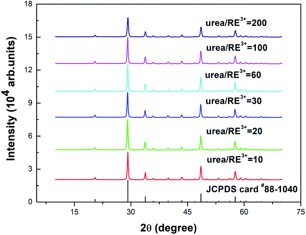 | ||
| Fig. 1 PXRD patterns of 5% Tb3+, 0.5% Eu3+ co-doped Y2O3 phosphors with different urea and RE3+ molar ratios of 10, 20, 30, 60, 100 and 200. | ||
Fig. 2(a–f) shows the FE-SEM images of the prepared samples. It can be clearly observed from Fig. 2 that the particle sizes of the Y2O3 phosphors decrease upon an increase in the molar ratio of urea to rare earth ions (the molar ratios of urea and rare earth ions are (a) 10, (b) 20, (c) 30, (d) 60, (e) 100 and (f) 200, respectively).
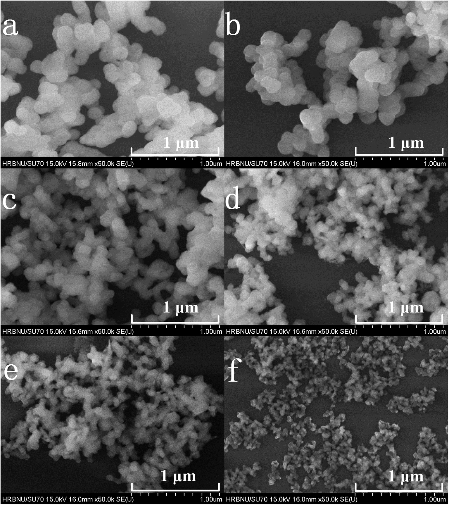 | ||
| Fig. 2 FE-SEM images of 5% Tb3+, 0.5% Eu3+ co-doped Y2O3 phosphors with different urea and RE3+ molar ratios of (a) 10, (b) 20, (c) 30, (d) 60, (e) 100 and (f) 200. | ||
Fig. 3 shows the statistical results of the particle sizes. The average particle size is calculated by the statistical particle size data. The average particle diameters of the Y2O3: Tb3+, Eu3+ phosphors are 184.02, 142.88, 97.37, 78.25, 48.46 and 30.27 nm, for molar ratios of urea and rare earth ions of 10, 20, 30, 60, 100 and 200, respectively. Therefore, the particle sizes were estimated to be about 200, 150, 100, 80, 50 and 30 nm, respectively.
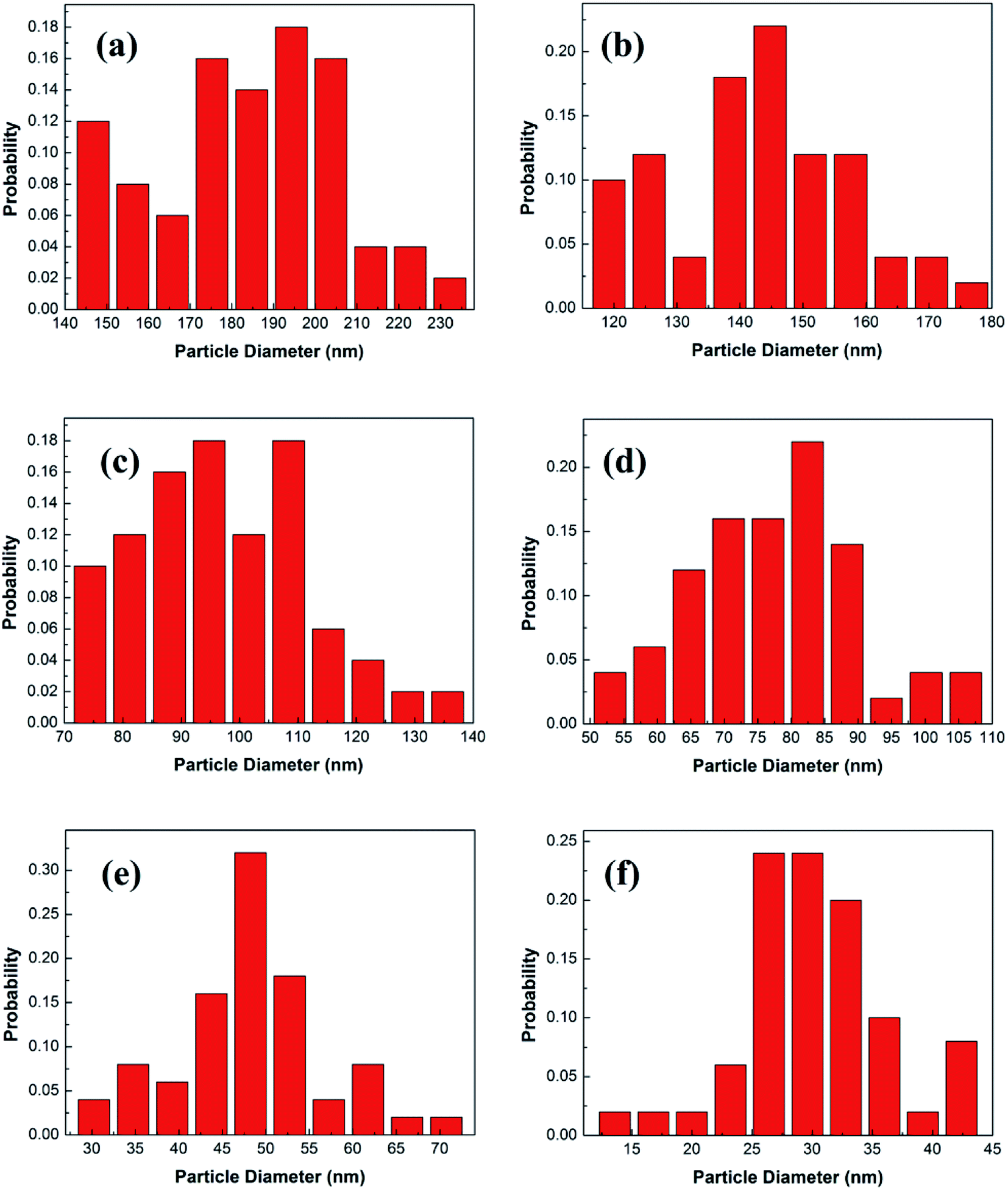 | ||
| Fig. 3 Particle diameter distributions of 5% Tb3+, 0.5% Eu3+ co-doped Y2O3 phosphors with different urea and RE3+ molar ratios of (a) 10, (b) 20, (c) 30, (d) 60, (e) 100 and (f) 200. | ||
3.2 Temperature sensing characteristics of the Y2O3: 5% Tb3+, 0.5% Eu3+ phosphors
Fig. 4 shows the excitation spectra of the prepared samples (the particle size is 100 nm) at room temperature. Curve (a) shows the excitation spectrum of the Y2O3: 5% Tb3+ phosphor, at a monitoring wavelength of 542.5 nm (consistent with the Tb3+ 5D4 → 7F5 transition). From curve (a), it can be seen that there is a strong excitation band in the range of 230–340 nm, which corresponds to the absorption transition of Tb3+ 4f–5d.25 At 484 nm, there is a weak excitation peak corresponding to Tb3+ 7F6–5D4.26 Curve (d) shows the excitation spectrum of the Y2O3: 0.5% Eu3+ phosphor, at a monitoring wavelength of 611.5 nm (consistent with the Eu3+ 5D0 → 7F2 transition). From curve (d), it can be seen that there is a strong excitation band at 210–280 nm corresponding to the charge transition absorption band of O2−–Eu3+.27 At 394.5 and 465 nm, there are two weak excitation peaks corresponding to the 7F0 → 5L6 and 7F0 → 5D2 transitions of Eu3+.26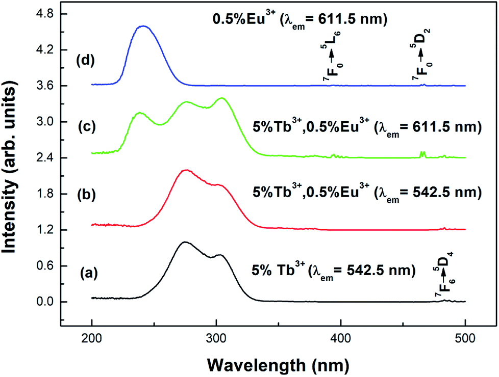 | ||
| Fig. 4 Excitation spectra of different samples with a particle size of 100 nm: (a) Y2O3: 5% Tb3+ (λem = 542.5 nm); (b) Y2O3: 5% Tb3+, 0.5% Eu3+ (λem = 542.5 nm); (c) Y2O3: 5% Tb3+, 0.5% Eu3+ (λem = 611.5 nm); (d) Y2O3: 0.5% Eu3+ (λem = 611.5 nm). | ||
Curves (b) and (c) show the excitation spectra of Y2O3: 5% Tb3+, 0.5% Eu3+ monitored at 542.5 nm and 611.5 nm. As can be seen from curve (b), when the luminescence of Tb3+ was monitored at 542.5 nm, no characteristic excitation was observed for Eu3+. However, as seen in curve (c), when monitoring the luminescence of Eu3+ at 611.5 nm, it was found that the Tb3+ (4f–5d) characteristic excitation band was particularly obvious. This indicates that the energy transfer from Eu3+ to Tb3+ is invalid, but the energy transfer from Tb3+ to Eu3+ is effective.28
Fig. 5 shows the emission spectra of the different samples at room temperature. Curves (a) and (b) show the emission spectra of the Y2O3: 5% Tb3+ and Y2O3: 5% Tb3+, 0.5% Eu3+ phosphors, at an excitation wavelength of 276 nm. Curve (c) shows the emission spectrum of the Y2O3: 0.5% Eu3+ phosphor at an excitation wavelength of 240 nm. The particle sizes of all three samples were 100 nm. Curve (a) shows the Tb3+ 4f–4f transition lines located at 484 nm (5D4 → 7F6), 542.5 nm (5D4 → 7F5), 583 nm (5D4 → 7F4), and 621 nm (5D4 → 7F3).25 Curve (c) shows the Eu3+ 4f–4f transitions, 580 nm (5D0 → 7F0), 593 nm (5D0 → 7F1), 611.5 nm (5D0 → 7F2), 651 nm (5D0 → 7F3), and 710 nm (5D0 → 7F4).29 Curve (b) shows the Eu3+ 4f–4f transition and Tb3+ 4f–4f transition emission peaks.
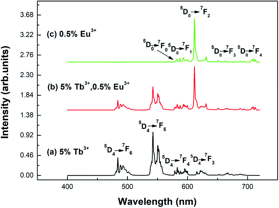 | ||
| Fig. 5 Emission spectra of different samples with a particle size of 100 nm: (a) Y2O3: 5% Tb3+ (λex = 276 nm); (b) Y2O3: 5% Tb3+, 0.5% Eu3+ (λex = 276 nm); (c) Y2O3: 0.5% Eu3+ (λex = 240 nm). | ||
In order to study the temperature sensing properties of the material in more depth, the temperature-dependent emission spectra of Y2O3: 5% Tb3+, 0.5% Eu3+ (the particle sizes of the samples are 200 nm, 150 nm, 100 nm, 80 nm, 50 nm and 30 nm, respectively) were measured in the temperature range of 313–513 K. Fig. 6(a–f) shows the temperature-dependent emission spectra of the samples at an excitation wavelength of 276 nm. In Fig. 6(a–f), it can be seen that the luminescence intensity of Tb3+ and Eu3+ decrease gradually as the temperature increases. However, the luminescence intensity of Eu3+ decreased more significantly. So, the FIR of Tb3+ to Eu3+ was observed to increase upon an increase in the temperature and therefore, the temperature change can be directly reflected by the FIR of Tb3+ and Eu3+.
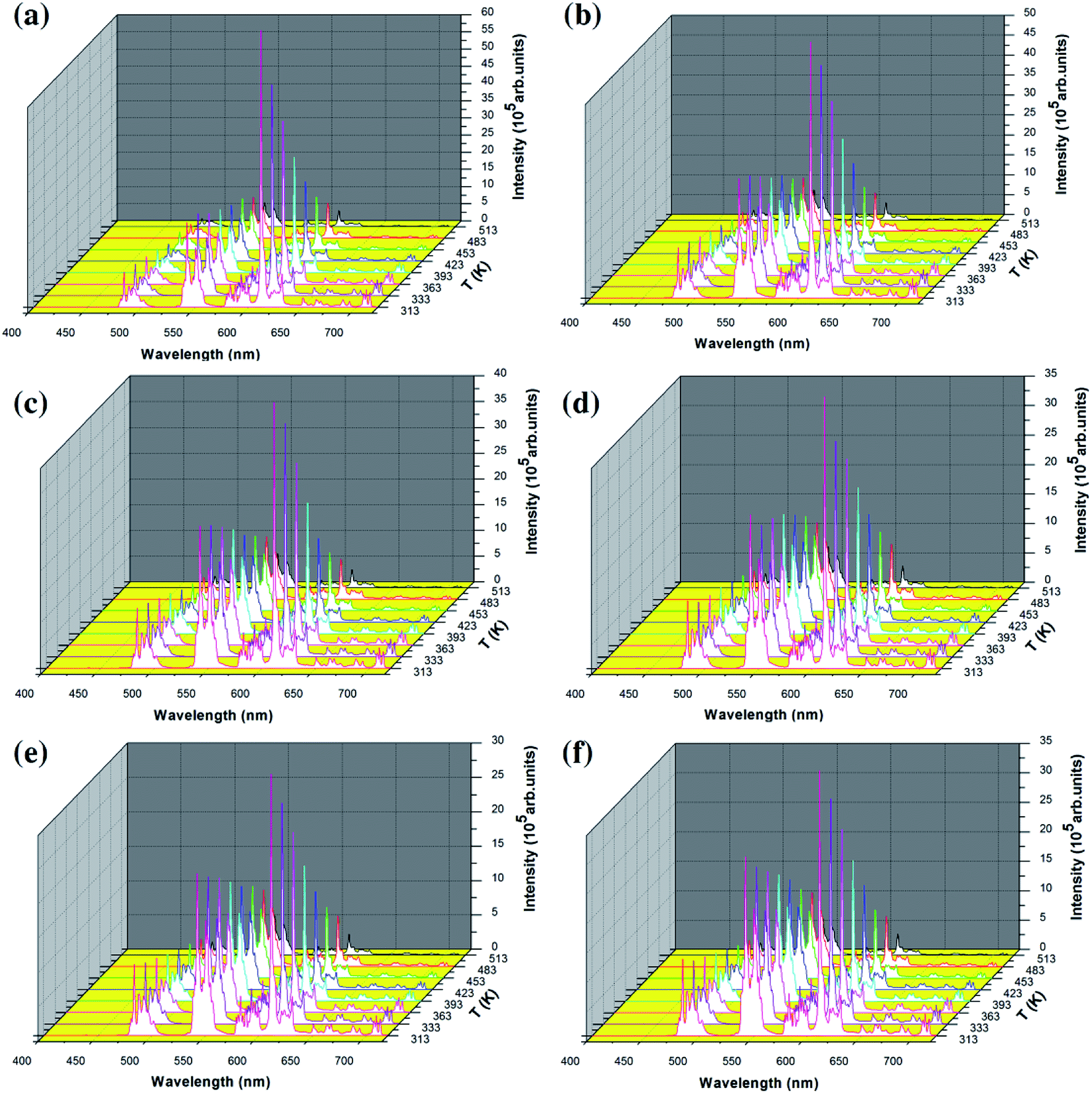 | ||
| Fig. 6 Temperature-dependent emission spectra of all of the samples by 276 nm excitation: (a–f) Y2O3: 5% Tb3+, 0.5% Eu3+ (the particle sizes of the samples were (a) 200 nm, (b) 150 nm, (c) 100 nm, (d) 80 nm, (e) 50 nm and (f) 30 nm, respectively). | ||
For a single doped material, the relationship between the luminescence intensity and temperature can be expressed by eqn (1):30,31
 | (1) |
In eqn (1), I0 is the luminescence intensity at 0 K, IT is the luminescence intensity at a specific temperature T, A is a constant, E is the heat quenching activation energy, KB is the Boltzmann constant and T is the absolute temperature.
In the co-doped Tb3+ and Eu3+ samples, the FIR of Tb3+ (5D4–7F5) to Eu3+ (5D0–7F2) in the variable temperature emission spectrum can be expressed as eqn (2), where the value of FIR be defined as R.
 | (2) |
By simplifying the derivation of eqn (2), a new formula R emerges:32
| R ≈ B + Ce−ΔE/KBT | (3) |
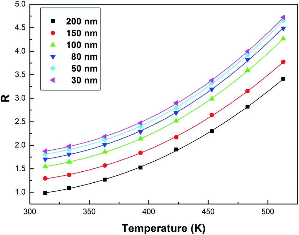 | ||
| Fig. 7 Curve R versus temperature in the Tb3+, Eu3+ co-doped Y2O3 phosphors (the particle sizes of the samples were 200 nm, 150 nm, 100 nm, 80 nm, 50 nm and 30 nm, respectively), the solid points represent the experimental data and the solid lines show the fitting result using eqn (3). | ||
| Particle size | B | C | ΔE/KB (K) | R2 |
|---|---|---|---|---|
| 200 nm | 0.800 ± 0.021 | 163.305 ± 14.164 | 2121.319 ± 47.073 | 0.99979 |
| 150 nm | 1.112 ± 0.016 | 189.417 ± 13.023 | 2187.751 ± 37.164 | 0.99987 |
| 100 nm | 1.369 ± 0.012 | 223.175 ± 11.418 | 2227.907 ± 27.593 | 0.99993 |
| 80 nm | 1.521 ± 0.023 | 237.407 ± 21.680 | 2245.071 ± 49.209 | 0.99978 |
| 50 nm | 1.633 ± 0.018 | 247.951 ± 17.875 | 2260.916 ± 38.814 | 0.99986 |
| 30 nm | 1.692 ± 0.022 | 250.347 ± 22.385 | 2264.333 ± 48.134 | 0.99979 |
From Fig. 7, the FIR can be seen to increase as the particle size of the sample decreases at the same temperature. This is due to size limitation effects (also known as the volume effect) of the interfaces of nanomaterials, which inhibits the energy transfer from Tb3+ to Eu3+ in the samples.33 Upon a decrease in the particle size of the sample, the inhibition becomes more obvious in terms of energy transfer. So, the luminescence intensity of Tb3+ relatively increases and the luminescence intensity of Eu3+ relatively decreases in the emission spectra, and the FIR of Tb3+ to Eu3+ increases.
In order to further demonstrate the impact of the size limitation effects on the energy transfer, as shown in Fig. 8, the fluorescence decay curves of Tb3+ at 5D4–7F5 (542.5 nm) in different samples was measured at an excitation of 276 nm. As can be seen from Fig. 8, due to the existence of energy transfer from Tb3+ to Eu3+, the luminescence decay curve of Tb3+ no longer features a simple single exponential change, but instead exhibits a non-exponential form. So, the average fluorescence lifetime can be used to indicate the fluorescence decay. Therefore, the average fluorescence lifetime τm can be defined as:34
 | (4) |
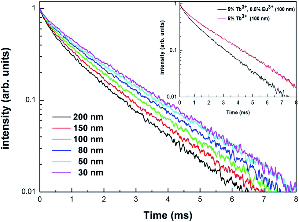 | ||
| Fig. 8 Fluorescence decay curves of the Tb3+ in Y2O3: 5% Tb3+, 0.5% Eu3+ phosphors (the particle sizes of the samples were 200 nm, 150 nm, 100 nm, 80 nm, 50 nm and 30 nm, respectively) monitoring 542.5 nm, by 276 nm excitation. The image shows the fluorescence decay curves of Tb3+ in Y2O3: 5% Tb3+ and Y2O3: 5% Tb3+, 0.5% Eu3+ phosphors with a particle size of 100 nm. | ||
Fig. 8 shows the fluorescence decay curves of Tb3+ in the Y2O3: 5% Tb3+, 0.5% Eu3+ and Y2O3: 5% Tb3+ phosphors, where the particle size of the samples was 100 nm. The fluorescence lifetimes of Tb3+ in the co-doped and single-doped phosphors was 1.206 and 1.611 ms, respectively. It can be seen that the fluorescence lifetime of Tb3+ in single-doped phosphors is significantly longer than that of co-doped phosphors, which further indicates that there is energy transfer from Tb3+ to Eu3+.35
For practical application, sensitivity is widely used to evaluate the temperature measurement performance of optical temperature sensing. The greater the sensitivity, the more suitable a material is to be used as a temperature sensing material. Sensitivity is defined as the rate of change of FIR with temperature, which can be expressed as:32
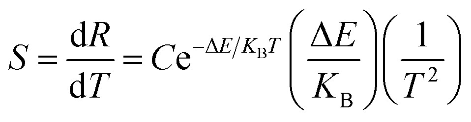 | (5) |
Fig. 9 shows the sensitivity (S) of samples with different particle sizes over a temperature range of 313–513 K. As can be clearly seen from Fig. 9, the sensitivity maxima were 0.0212 K−1 (200 nm), 0.0222 K−1 (150 nm), 0.0246 K−1 (100 nm), 0.0255 K−1 (80 nm), 0.0260 K−1 (50 nm) and 0.0261 K−1 (30 nm) at 513 K, respectively. When the temperature is the same, the smaller the particle size of the sample, the greater the sensitivity of the sample. When the particle size of the sample decreases, the surface defects in the sample increase and the phonon vibration mode increases, increasing the coupling strength between electrons and phonons, which makes the luminescence properties of the sample more sensitive to temperature, therefore increasing the sensitivity of the sample. It can be concluded that the sensitivity can be improved by reducing the particle sizes of the samples.
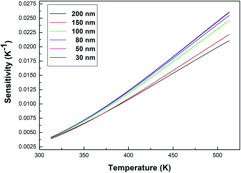 | ||
| Fig. 9 Curves of sensitivity versus temperature for the Tb3+, Eu3+ co-doped Y2O3 phosphors (the particle sizes of the samples were 200 nm, 150 nm, 100 nm, 80 nm, 50 nm and 30 nm, respectively). | ||
The relative sensitivity can be represented by the following formula:32
 | (6) |
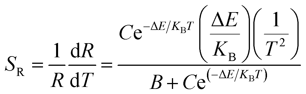
As can be seen from Fig. 10, the relative sensitivity image of this sample presents a nonmonotonic trend. As the temperature increases, the relative sensitivity of each sample first increases and then decreases. As can be clearly observed in Fig. 10, at the same temperature, the relative sensitivity decreases as the particle size decreases. The relative sensitivity maxima were 0.00683 K−1 (200 nm, 430 K), 0.00615 K−1 (150 nm, 456 K), 0.00593 K−1 (100 nm, 469 K), 0.00577 K−1 (80 nm, 475 K), 0.00567 K−1 (50 nm, 479 K) and 0.00560 K−1 (30 nm, 483 K), respectively, due to the obvious increase in the R value with a decrease in the particle size. And, the value of S increased slightly, so according to eqn (6), the SR value decreases upon a decrease in the particle size.
 | ||
| Fig. 10 Curves of relative sensitivity versus temperature for the Tb3+, Eu3+ co-doped Y2O3 phosphors (the particle sizes of the samples were 200 nm, 150 nm, 100 nm, 80 nm, 50 nm and 30 nm, respectively). | ||
The CIE (Commission International del’ Eclairage) color coordinates of the Y2O3: 5% Tb3+, 0.5% Eu3+ phosphors with different particle sizes were calculated at 313–513 K, and the results are shown in Fig. 11(a–f). In Fig. 11, it can be see that as the temperature increases, the luminescent colors of the samples change from orange to green. So, the change in temperature is directly reflected by the change in the color of the luminescence. In addition, from Fig. 11, it can also be observed that the when particle size is larger, the range of the change in the color of the luminescence of the sample is greater, therefore the color of the luminescence changes more obviously with temperature.
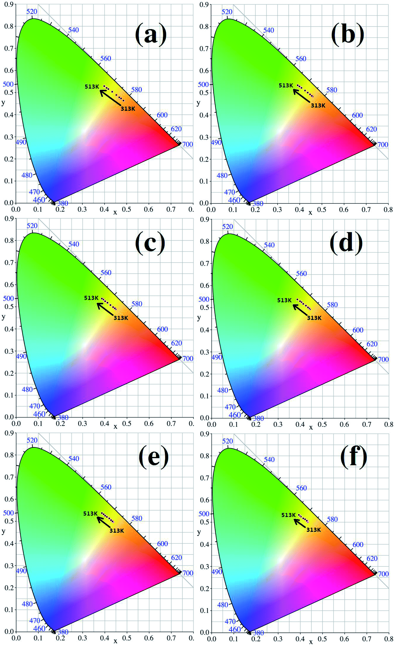 | ||
| Fig. 11 CIE coordinate diagrams for each sample (the particle sizes of the samples were (a) 200 nm, (b) 150 nm, (c) 100 nm, (d) 80 nm, (e) 50 nm and (f) 30 nm, respectively). | ||
4. Conclusions
In this paper, urea was used as a precipitation agent to synthesize Tb3+, Eu3+ co-doped Y2O3 nanophosphors by way of a homogeneous precipitation method. The size of the sample particles was controlled by changing the molar ratio of urea and rare earth ions. The particle size of the Y2O3: Tb3+, Eu3+ phosphor was observed to be around 200, 150, 100, 80, 50, and 30 nm when the molar ratio of urea and rare earth ions was 10, 20, 30, 60, 100 and 200, respectively. The optical temperature sensing properties of Y2O3: 5% Tb3+, 0.5% Eu3+ phosphors with different particle sizes were studied. The research shows that the FIR of Tb3+ to Eu3+ increased upon an increase in the temperature for all sized samples. Therefore, it was identified that FIR can be used to characterize temperature. Because of surface effects, the sensitivity was observed to increase upon a decrease in the particle size. However, due to size limitation effects, the relative sensitivity value decreased upon a decrease in the sample particle size. In addition, we also found that the luminescence color of the sample changed from orange to green when the temperature ranged from 313–513 K. So, the change in temperature can be directly reflected by the change in the luminescence color. The above results show that this work provides help for the study of the influence of size limitation and surface effects on the optical temperature sensing properties of nanomaterials.Conflicts of interest
There are no conflicts of interest to declare.Acknowledgements
This study was supported by the Open Project Program of the Key Laboratory for Photonic and Electric Bandgap Materials, Ministry of Education, Harbin Normal University, China (Grant no. PEBN201614).References
- X. F. Wang, Q. Liu, Y. Y. Bu, C. S. Liu, T. Liu and X. H. Yan, RSC Adv., 2015, 5, 86219–86236 RSC.
- J. Liu, R. V. Deun and A. M. Kaczmarek, J. Mater. Chem. C, 2016, 4, 9937–9941 RSC.
- D. Q. Chen, S. Liu, Y. Zhou, Z. Y. Wan, P. Huang and Z. G. Ji, J. Mater. Chem. C, 2016, 4, 9044–9051 RSC.
- F. Vetrone, R. Naccache, A. Zamarron, A. J. Fuente, F. S. Rodriguez, L. M. Maestro, E. M. Rodriguez, D. Jaque, J. G. Sole and J. A. Capobianco, ACS Nano, 2010, 4, 3254–3258 CrossRef CAS PubMed.
- V. Lojpur, Z. Antic and M. D. Dramicanin, Phys. Chem. Chem. Phys., 2014, 16, 25636–25641 RSC.
- T. S. Atabaev, O. S. Jin, J. H. Lee, D. W. Han, H. H. T. Vu, Y. H. Hwang and H. K. Kim, RSC Adv., 2012, 2, 9495–9501 RSC.
- L. Yan, B. Li, Y. F. Song, Z. Lv, X. X. Zheng, Q. Wu and Y. Q. Yang, Opt. Lett., 2017, 42, 3793–3795 CrossRef CAS PubMed.
- Y. Y. Tu, S. L. Zhao, D. Y. He, T. Wu, H. Zhang, R. S. Lei, L. H. Huang and S. Q. Xu, J. Mater. Chem. C, 2018, 6, 7063–7069 RSC.
- F. Huang and D. Q. Chen, J. Mater. Chem. C, 2017, 5, 5176–5182 RSC.
- A. K. Parchur and R. S. Ningthoujam, Dalton Trans., 2011, 40, 7590–7594 RSC.
- J. K. Cao, D. K. Xu, F. F. Hu, X. M. Li, W. P. Chen, L. P. Chen and H. Guo, J. Eur. Ceram. Soc., 2018, 38, 2753–2758 CrossRef CAS.
- J. K. Cao, X. M. Li, Z. X. Wang, Y. L. Wei, L. P. Chen and H. Guo, Sens. Actuators, B, 2016, 224, 507–513 CrossRef CAS.
- J. K. Cao, F. F. Hu, L. P. Chen, H. Guo, C. K. Duan and M. Yin, J. Am. Ceram. Soc., 2017, 100, 2108–2115 CrossRef CAS.
- S. Katyayan and S. Agrawal, J. Mater. Sci.: Mater. Electron., 2017, 28, 18442–18454 CrossRef CAS.
- D. W. Wen, J. J. Feng, J. H. Li, J. X. Shi, M. M. Wu and Q. Su, J. Mater. Chem. C, 2015, 3, 2107–2114 RSC.
- C. D. S. Brites, P. P. Lima, N. J. O. Silva, A. Millan, V. S. Amaral, F. Palacio and L. D. Carlos, Adv. Mater., 2010, 22, 4499–4504 CrossRef CAS PubMed.
- C. D. S. Brites, P. P. Lima, N. J. O. Silva, A. Millan, V. S. Amaral, F. Palacio and L. D. Carlos, New J. Chem., 2011, 35, 1177–1183 RSC.
- Y. J. Cui, H. Xu, Y. F. Yue, Z. Y. Guo, J. C. Yu, Z. X. Chen, J. K. Gao, Y. Yang, G. D. Qian and B. L. Chen, J. Am. Chem. Soc., 2012, 134, 3979–3982 CrossRef CAS PubMed.
- D. Y. Li, Y. X. Wang, X. R. Zhang, K. Yang, L. Liu and Y. L. Song, Opt. Commun., 2012, 285, 1925–1928 CrossRef CAS.
- Y. C. Kang, H. S. Roh and S. B. Park, Adv. Mater., 2000, 12, 451–453 CrossRef CAS.
- Y. Tian, B. N. Tian, C. E. Cui, P. Huang, L. Wang and B. J. Chen, RSC Adv., 2015, 5, 14123–14128 RSC.
- S. K. Talkhoncheh, M. Haghighi, S. Minaei, H. Ajamein and M. Abdollahifar, RSC Adv., 2016, 6, 57199–57209 RSC.
- X. J. Wei, W. Wang and K. Z. Chen, Dalton Trans., 2013, 42, 1752–1759 RSC.
- Z. H. Xu, Y. F. Bi, H. Yu, J. Y. Lin, F. Ding, Y. G. Sun and Y. Gao, New J. Chem., 2017, 41, 8959–8964 RSC.
- J. W. Wang, H. W. Song, B. J. Sun, X. G. Ren, B. J. Chen and W. Xu, Chem. Phys. Lett., 2003, 379, 507–511 CrossRef CAS.
- J. H. Xiong, Q. Y. Meng and W. J. Sun, J. Rare Earths, 2016, 34, 251–258 CrossRef CAS.
- X. Bai, H. W. Song, L. X. Yu, L. M. Yang, Z. X. Liu, G. H. Pan, S. Z. Lu, X. G. Ren, Y. Q. Lei and L. B. Fan, J. Phys. Chem. B, 2005, 109, 15236–15242 CrossRef CAS PubMed.
- K. Li, S. S. Liang, M. M. Shang, H. Z. Lian and J. Lin, Inorg. Chem., 2016, 55(15), 7593–7604 CrossRef CAS PubMed.
- S. D. Li, Q. Y. Meng, S. C. Lü and W. J. Sun, J. Lumin., 2018, 200, 103–110 CrossRef CAS.
- Y. Tian, B. J. Chen, R. N. Hua, N. S. Yu, B. Q. Liu, J. S. Sun, L. H. Cheng, H. Y. Zhong, X. P. Li, J. S. Zhang, B. N. Tian and H. Zhong, CrystEngComm, 2012, 14, 1760–1769 RSC.
- Y. C. Chang, C. H. Liang, S. A. Yan and Y. S. Chang, J. Phys. Chem. C, 2010, 114, 3645–3652 CrossRef CAS.
- Y. Gao, F. Huang, H. Lin, J. C. Zhou, J. Xu and Y. S. Wang, Adv. Funct. Mater., 2016, 26, 3139–3145 CrossRef CAS.
- Q. Y. Meng, B. J. Chen, W. Xu, Y. M. Yang, X. X. Zhao, W. H. Di, S. Z. Lu and X. J. Wang, J. Appl. Phys., 2007, 102, 093505 CrossRef.
- R. Lisiecki, W. R. Romanowski and T. Lukasiewicz, Appl. Phys. B, 2006, 83, 255–259 CrossRef CAS.
- K. Li, M. M. Shang, H. Z. Lian and J. Lin, J. Mater. Chem. C, 2016, 4, 5507–5530 RSC.
| This journal is © The Royal Society of Chemistry 2019 |