 Open Access Article
Facile synthesis of polypyrrole nanofiber (PPyNF)/NiOx composites by a microwave method and application in supercapacitors
Huijun Liu,
Qiang Zhao,
Kewei Wang,
Zhen Lu,
Feng Feng * and
Yong Guo
 *
*
College of Chemistry and Environmental Engineering, The University of Shanxi Datong, Datong, 037009, P. R. China
First published on 28th February 2019
Abstract
In this study, polypyrrole nanofiber (PPyNF)/NiOx composites were synthesized by a simple and fast microwave method. The samples were characterized using differential scanning calorimetry and thermal gravimetric analysis (DSC/TGA), X-ray photoelectron spectroscopy (XPS) and scanning electron microscopy (SEM). Furthermore, the synthesized PPyNF/NiOx nanocomposites were electrochemically characterized using galvanostatic charge–discharge, cyclic voltammetry and electrochemical impedance spectroscopy (EIS) techniques. They showed the highest specific capacitance of 657 F g−1 at 0.5 A g−1, demonstrating their potential application in supercapacitors.
1. Introduction
Supercapacitors are high-capacity devices that are considered promising candidates in energy storage, owing to their higher energy density than conventional capacitors and larger power density than batteries.1–4 The core of supercapacitors is the electrode material, which directly dominates the performance of energy storage. Among the electroactive materials used for supercapacitors, nickel oxide (NiO) has been identified as an influential candidate because of its high theoretical specific capacitance, high electrochemical stability and excellent redox activities.5–9 Unfortunately, its practical applications have been limited by its short charge–discharge cycle life. To overcome this shortcoming, scientists have studied the fabrication of nanohybrid materials by integrating conducting polymers (CPs), to improve the cyclability compared with pristine metal oxides.10–12 For example, Ji et al. synthesised polypyrrole/flower-like porous NiO nanocomposites, which exhibits a remarkable cycling stability and shows a capacitance of 595 F g−1, with perfect cycling life (capacitance loss is less than 20% after 1000 cycles).13 Another important work had been conducted by Cai et al., who fabricated polyaniline (PANI)/nano-NiO nanocomposite by hydrothermal method with β-cyclodextrin as a template. The composite processed a high specific capacitance (2122.75 F g−1 at 0.1 A g−1 in 0.05 M KI electrolyte solution) and excellent cycle performance (86% capacitance retention after 1000 cycles at 1.5 A g−1).14 Furthermore, researchers determined that the nanostructure and morphology of conducting polymers, such as nanotube, nanospheres, nanofiber, flower-like and core–shell structures, significantly influence electrochemical properties.15–17 For instance, Wang et al. prepared PANI@multiwall carbon nanotube (MWCNT) hybrid films through in situ electrochemistry, producing PANI nanowires with a diameter of 8 nm confined within a 10 nm-diameter MWCNT porous membrane; the membranes exhibited a good electrochemical capacitance of 296 F g−1 with a capacitance retention of 95% after 2000 cycles.18 Li et al. proposed a polyaniline/polypyrrole (PANI/PPy) composite nanofibers with core–shell structures electrode for supercapacitor applications. The composite nanofibers showed the highest specific capacitance of 834.6 F g−1 at the scan rate of 5 mV s−1.19 Another similar research has been reported by Cai's group, as active electrode materials, graphene nanosheet and PPy nanotube nanocomposite show a highest specific capacitance of 368 F g−1 with an excellent capacitive retention of 91.4% after 1000 cycles.20 These results indicate that the nanostructure of CP composites exhibit potential in the development of high-performance electrode materials.The most commonly used conducting polymers include polypyrrole (PPy), polyaniline (PANI) and their derivatives.21–23 In recent years, PPy composites have been widely used in supercapacitors due to their electrochemical stability, high conductivity (10–100 S cm−1) and intrinsic flexibility;24–26 PPy also possesses better electronic and electrochemical properties compared with PANI. In this study, facile and energy efficient microwave assisted solid-state synthesis of PPy/NiOx nanocomposite was reported. The synthesised samples were further electrochemically investigated for their performance as potential supercapacitors.
2. Experimental
2.1. Materials
All the chemicals purchased were reagent grade. Nickel nitrate hexahydrate (Ni(NO3)2·6H2O, 98.5%), ferric chloride (FeCl3), potassium hydroxide (KOH) and pyrrole (Py) were obtained from Aladdin Industrial Corporation (Aladdin Reagent Co., Ltd.), Shanghai, China. All aqueous solutions were prepared in deionized water (18.2 MΩ cm of resistivity at 25 °C).2.2. Preparation of PPyNF
The polypyrrole nanofiber (PPyNF) was synthesized from V2O5 nanofibers and pyrrole according to the literature.27 Pyrrole (1 mL) were dissolved in 1 M HCl solution (60 mL), and then, a certain amount of V2O5 nanofibers (1–2 mL) were added. After stirring for 20 minutes, APS solution (1 g APS dissolved in 20 mL 1 M HCl) was added to the above solution. Under magnetic stirring for 20 minutes at 25 °C, the resulting suspension was filtered and washed several times with deionized water and acetone until filtrate was colorless. Finally, it was vacuum dried at 80 °C for 12 h.2.3. Preparation of PPyNF/NiOx nanocomposites
The PPyNF/NiOx nanocomposites were prepared through a facile and ultrafast microwave solid-state approach. In a typical procedure, 40 mg Ni(NO3)2·6H2O as metal precursor and 50 mg PPyNF as thermal conductivity layer were mixed to each other and finely powdered in an agate mortar. The PPyNF was used as the microwave absorbing material and heating layer to facilitate the decomposition of Ni(NO3)2·6H2O. This leads to the formation of NiOx nanocomposites under microwave irradiation due to the strong microwave absorption of PPyNF.8 The mechanism of formation of the PPyNF/NiOx nanocomposites is schematically shown in Scheme 1. Subsequently, the mixture was transferred to an alumina crucible and put into a domestic microwave oven (PANASONIC NN-GF352M, 2450 MHz, 1000 W) with a power of 800 W for 60 s. After a while, the powder of PPyNF/NiO nanocomposite were collected. The other PPyNF/NiOx nanocomposite of different material ratios, microwave radiation time and power were also prepared. All the related information is given in Table 1.2.4. Characterization
Thermal gravimetric analysis (TGA) measurement and Differential scanning calorimetric (DSC) analyses were performed using a Netzsch STA 449C (Germany) with a heating rate of 10 °C min−1 and temperature ranging from 30 °C to 1000 °C under nitrogen atmosphere. X-ray diffraction (XRD) patterns with Cu target (36 kV, 25 mA) were performed in 2θ range from 5° to 60°, with a step size of 0.02° and a scanning speed of 8° min−1. Scanning electron microscopy (SEM) of the samples was analyzed using KYKY-EM3800. All electrochemical measurements (ChenHua CHI660E) were evaluated in single compartment three-electrode electrochemical cell containing 6 M KOH as an electrolyte. The working electrode was prepared by mixing as-synthesized PPy/NiOx nanocomposites (active materials) with acetylene black (conductive agent) and polyvinylidene fluoride (PVDF, binder) in a 80![[thin space (1/6-em)]](https://www.rsc.org/images/entities/char_2009.gif) :
:![[thin space (1/6-em)]](https://www.rsc.org/images/entities/char_2009.gif) 10
10![[thin space (1/6-em)]](https://www.rsc.org/images/entities/char_2009.gif) :
:![[thin space (1/6-em)]](https://www.rsc.org/images/entities/char_2009.gif) 10 weight ratio using N-methyl-2-pyrrolidone (NMP) as a solvent to make a homogeneous slurry. After smeared the slurry into a Ni foam (1 × 1 cm2) current collector, the Ni foam with slurry was dried at 80 °C for 24 h and then pressed under a pressure of 10 MPa. The loading mass of active material was approximately 0.72 mg cm−2. Correspondingly, the platinum (Pt) foil and mercury/mercury oxide electrode (Hg/HgO) were used as the counter electrode and a reference electrode, respectively.
10 weight ratio using N-methyl-2-pyrrolidone (NMP) as a solvent to make a homogeneous slurry. After smeared the slurry into a Ni foam (1 × 1 cm2) current collector, the Ni foam with slurry was dried at 80 °C for 24 h and then pressed under a pressure of 10 MPa. The loading mass of active material was approximately 0.72 mg cm−2. Correspondingly, the platinum (Pt) foil and mercury/mercury oxide electrode (Hg/HgO) were used as the counter electrode and a reference electrode, respectively.
3. Results and discussion
3.1. Synthesis and characterization
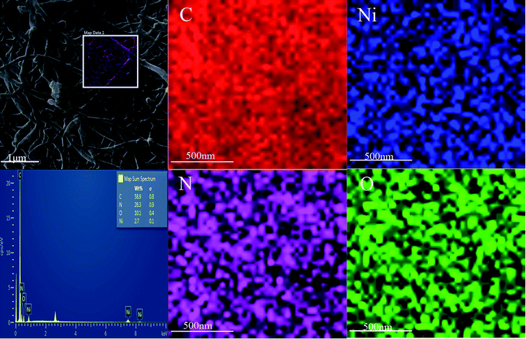
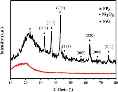
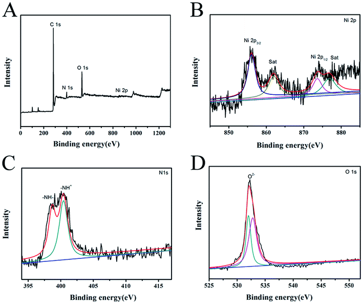
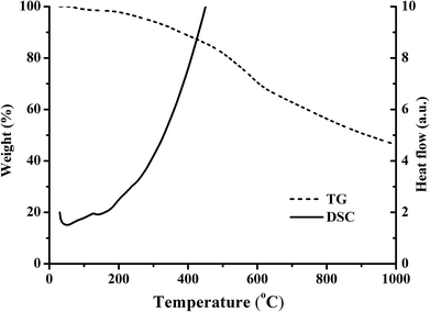
The SEM images of PPyNF and PPyNF/NiOx nanocomposites were shown in Fig. 1A–F, respectively. Fig. 1A and B show the SEM images of PPyNFs, which were approximately 100 nm in diameter and 5000 nm in length. Likewise, Fig. 1C–F show the SEM images of PPyNF/NiOx nanocomposites, where nano-particle structured NiOx was observed, where a mass of NiOx nanoparticles were grown intricately on the surface of PPyNFs. The average diameter of nanoparticles was found to be about 100 nm. The lower microwave power, 600 W, yields a lower amount of product compared to the higher microwave power, 800 W (in Fig. 1D and E). Additionally, the higher microwave (1000 W) power may affect the NiOx particles, making agglomeration (in Fig. 1E and F). The purity of synthesized PPyNF/NiOx nanocomposites was suggested by EDS spectra shown in Fig. 2, where C, N, Ni and O were detected. Fig. 3 presents the XRD patterns of PPyNF/NiOx composite. PPyNF revealed a sharp and intense diffraction peak located at 21. For PPyNF/NiOx composite, the diffraction peaks at 36.78°, 42.92° and 62.4°, which can be assigned to the (111), (200) and (220) reflections of NiO, respectively, as per the JCPDS PDF# 78-0643. Diffraction peaks were also observed at 2θ degrees of 31.67°, 45.42°, 56.43°, 66.19° and 75.26°, which can be attributed to the (202), (111), (002), (004) and (311) reflections of Ni2O3 as per the JCPDS PDF# 14-0481 ref. 28, respectively. These XRD results indicate that NiOx was a mixture of NiO and Ni2O3. The oxidation states of NiOx nanoparticles were also determined by XPS (Fig. 4). The full survey scan spectrum (Fig. 4A) shows the peaks of four elements (C, N, Ni, and O). As shown in Fig. 4B, in the spectrum of Ni 2p, the major peaks at 856.2 and 874 eV correspond to the Ni 2p3/2 and Ni 2p1/2 spin orbit levels, respectively. The binding energy gap between Ni 2p3/2 and Ni 2p1/2 approached 17.8 eV, indicating that the nanocomposite contains Ni2+ and Ni3+. Two similar peaks were noted at 398 and 399.4 eV, which were identified in the N1s spectrum in Fig. 4C and assigned to neutral amine nitrogen and amine nitrogen (N+) within the PPy, respectively.29 The O 1s spectrum is single peaks at 532.5 eV (Fig. 4D), which belong to O2− forming oxides with Ni. Fig. 5 shows the TGA-DSC spectra of PPyNF–NiOx nanocomposites from RT to 1000 °C. The PPyNF–NiOx nanocomposites exhibited a three-step thermal degradation. The initial weight loss, which is approximately 100–250 °C, was mainly due to the evaporation of moisture. The second weight loss, which is approximately 350–600 °C, was attributed to the decomposition of NiOx. The final weight loss, which was approximately 600–1000 °C, was caused by the generalized PPy backbone degradation. DSC spectra shows clear transition around 160 °C. Here, the upper peak indicates that the material absorbs more heat as compared to the reference sample which corresponds to the exothermic transition of the material.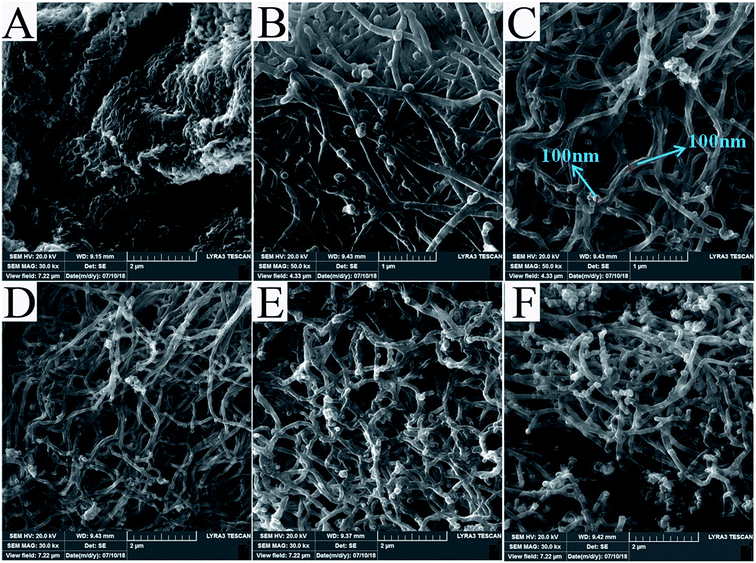 | ||
| Fig. 1 SEM images of as-prepared samples (A) and (B) PPyNF and (C)–(E) and (F) PPyNF–NiOx nanocomposite. | ||
3.2. Electrochemical performance
To determine the optimal preparation conditions, we have tested the electrochemical properties of samples a–g and showed their specific capacitances at different current densities in Fig. 6. As shown in Fig. 6A, the specific capacitance of PPyNF/NiOx electrode presented an increase-and-decrease trend with increasing Ni(NO3)2·6H2O. With Ni(NO3)2·6H2O mass ranging from 30 mg to 40 mg, the content of NiOx generated increased and the specific capacitance increased gradually. However, when Ni(NO3)2·6H2O mass increased to 50 mg, the content of crystallinity water of the precursor could not be ignored. When the content of crystallinity water is too high, the microwave energy absorbed by PPyNF becomes insufficient, and the precursor cannot be completely decomposed, leading to decreases in the electrochemical properties of the nanocomposite. For instance, the specific capacitance of sample b reached 657 F g−1 at 0.5 A g−1, which was higher than those of samples a and c. The effect of microwave time and microwave power on special capacitors have been shown in Fig. 6B and C. It can be seen from Fig. 6B and C, when the reaction time is 60 s and the microwave power is 800 W, sample b showed the best special capacitor. Extremely low microwave power or considerably short reaction time will lead to insufficient microwave energy absorbed by the heating layer, and the precursor cannot be completely decomposed, whereas extremely high microwave power or notably long reaction time will affect the growth of NiOx particles. For example, the specific capacitance of sample b was higher than those of samples d and e. As shown in Fig. 1D–F, the lower microwave power yields a lower amount of product and the higher microwave power may affect the NiOx particles, making agglomeration. Thus, the optimum experimental conditions for synthesis of PPyNF/NiOx nanocomposite include a 50![[thin space (1/6-em)]](https://www.rsc.org/images/entities/char_2009.gif) :
:![[thin space (1/6-em)]](https://www.rsc.org/images/entities/char_2009.gif) 40 mass ratio, 800 W microwave power and 60 s microwave time. The specific capacitances are 657, 538, 510, 480 and 460 F g−1at the current densities of 0.5, 1, 2, 3 and 5 A g−1, respectively, showing the rate capability of the synthesized sample b (Fig. 6D).
40 mass ratio, 800 W microwave power and 60 s microwave time. The specific capacitances are 657, 538, 510, 480 and 460 F g−1at the current densities of 0.5, 1, 2, 3 and 5 A g−1, respectively, showing the rate capability of the synthesized sample b (Fig. 6D).
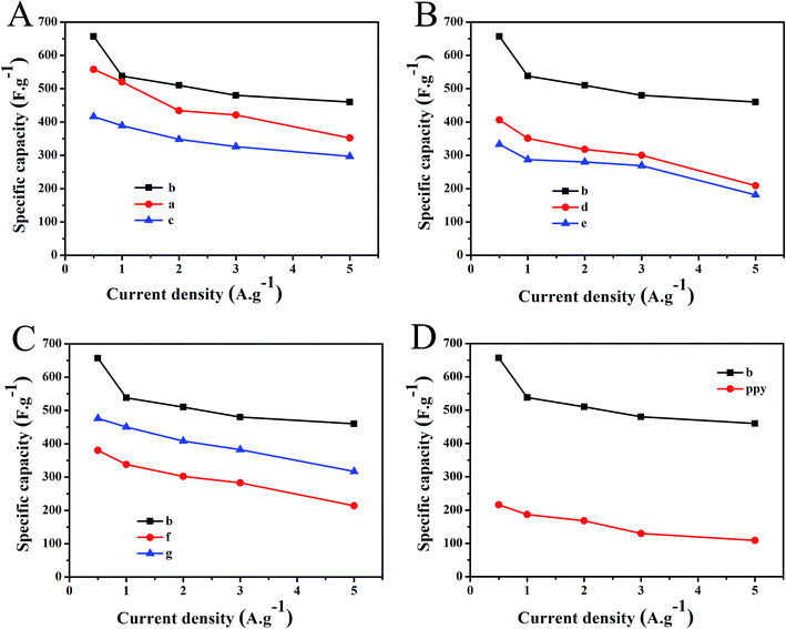 | ||
| Fig. 6 Specific capacity of PPyNF–NiOx nanocomposite at different current density (A) sample a–c, (B) sample b–e, (C) sample b–g, (D) sample b and PPy. | ||
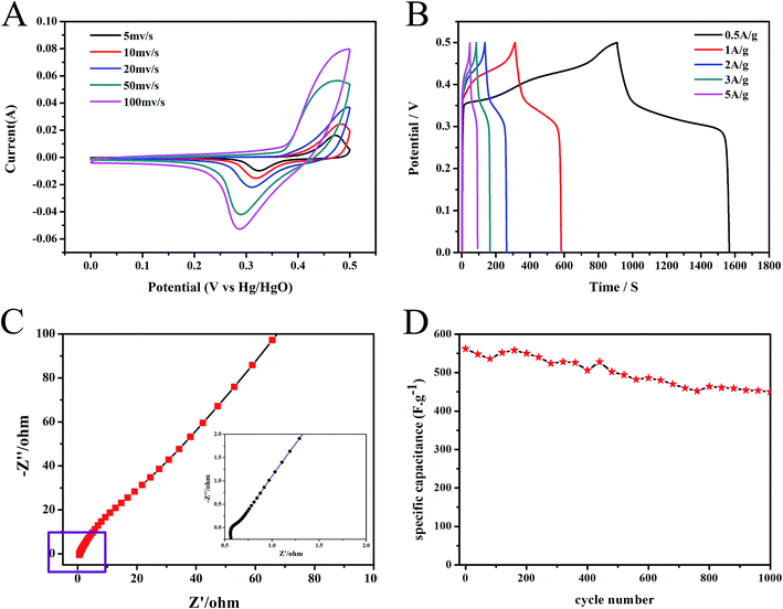
The electrochemical performance of PPyNF/NiOx nanocomposite of sample b was investigated by cyclic voltammetry (CV), galvanostatic charge/discharge (GCD), and electrochemical impedance spectroscopy (EIS) measurements. As shown in Fig. 7A, the CV curves of PPyNF/NiOx showed a pair of well-defined redox peaks at all scan rates, which were due to the reversible faradaic redox reaction between Ni2+ and Ni3+. This process might be represented by the following equation:30
| Ni(II)S + OH− ↔ Ni(II)OHad + e− |
With the increase in scan rate, the anodic and cathodic peak potentials shifted in more positive and negative directions, respectively, causing no significant change in the shape of CV curves. This finding indicates the good rate capability of PPyNF/NiOx. The pseudocapacitance behaviour was also observed in the GCD curves of PPyNF/NiOx electrode within a potential window of 0–0.5 V at all current densities (Fig. 7B). To further characterise the performance of the supercapacitors, the long-term cycle stability of the electrodes was examined by repeated GCD testing at a current density of 1 A g−1, revealing an the excellent cycle life with 80% retention of specific capacitance after 1000 cycles (Fig. 7C). The Nyquist plot of sample b was measured using an AC voltage with 5 mV amplitude with a frequency range of 100 kHz to 0.01 Hz at the open circuit potential. As depicted in Fig. 7D, the small semi-circle at higher frequencies indicates a low charge transfer resistance with slight diffusion at lower frequencies. This result further affirms the excellent electrochemical cycling stability of PPyNF/NiOx nanocomposite which showed potential application as electrode material for supercapacitors. Table 2 compares the specific capacitance and preparation method between the system of our present work and the reported values. The PPyNF/NiOx nanocomposites successfully increase the specific capacitance by the simple and fast microwave method. Overall, this study suggests that PPyNF/NiOx nanocomposites feature a number of advantages over numerous materials when considering various strategies.
| Materials | Prepared method | Capacity | Ref. |
|---|---|---|---|
| 3D flower-like porous structure NiO@PPy composite | Hydrothermal method | 595 F g−1 (1 A g−1) | 13 |
| PANI/nano-NiO composite | Hydrothermal method | 2122.75 F g−1 (0.1A g−1) | 14 |
| N-doped porous carbon (NPC)/NiO composites | Liquid oxidation | 404 F g−1 (1 A g−1) | 31 |
| Carbon cloth nickel oxide–polyaniline (EC-NiO/PANI) | Hydrothermal method | 193 F g−1 (0.5 A g−1) | 32 |
| Polypyrrole nanofiber (PPyNF)/NiOx composites | Microwave method | 657 F g−1 (0.5 A g−1) | This work |
4. Conclusions
PPyNF/NiOx nanocomposite have been successfully synthesized via ultrafast microwave irradiation method respectively. The PPyNF/NiOx nanocomposite showed highest specific capacitance (657 F g−1 at a current density of 0.5 A g−1) with mass ratio of 50![[thin space (1/6-em)]](https://www.rsc.org/images/entities/char_2009.gif) :
:![[thin space (1/6-em)]](https://www.rsc.org/images/entities/char_2009.gif) 40 (PPyNF/Ni(NO3)2·6H2O), microwave heating time of 60 s and microwave power of 800 W. In addition, excellent cycling stability with capacitance retention of 80% of the initial value after 1000 cycles was further investigation at a current density of 1 A g−1. Thus, the PPyNF/NiOx nanocomposite can be considered to a potential material for energy storage.
40 (PPyNF/Ni(NO3)2·6H2O), microwave heating time of 60 s and microwave power of 800 W. In addition, excellent cycling stability with capacitance retention of 80% of the initial value after 1000 cycles was further investigation at a current density of 1 A g−1. Thus, the PPyNF/NiOx nanocomposite can be considered to a potential material for energy storage.
Conflicts of interest
There are no conflicts to declare.Acknowledgements
The authors thank the financial support of the Natural Science Foundation of China (21073113).References
- H. Kashani, L. Y. Chen, Y. k. Ito, J. H. Han, A. k. Hirata and M. W. Chen, Nano Energy, 2016, 19, 391–400 CrossRef CAS.
- A. H. P. Oliveira and H. P. Oliveira, J. Power Sources, 2014, 268, 45–49 CrossRef.
- S. Chu and A. Majumdar, Nature, 2012, 488, 294–303 CrossRef CAS PubMed.
- C. Liu, F. Li, L. P. Ma and H. M. Cheng, Adv. Mater., 2010, 22, E28–E62 CrossRef CAS PubMed.
- Y. Mao, Q. Y. Kong, B. k. Guo, L. Shen, Z. X. Wang and L. Q. Chen, Electrochim. Acta, 2013, 105, 162–169 CrossRef CAS.
- J. W. Lee, T. Ahn, J. H. Kim, J. M. Ko and J. D. Kima, Electrochim. Acta, 2011, 56, 4849–4857 CrossRef CAS.
- X. M. Wu, Q. G. Wang, W. Z. Zhang, Y. Wang and W. X. Chen, Electrochim. Acta, 2016, 211, 1066–1075 CrossRef CAS.
- Y. H. Bi, A. Nautiyal, H. P. Zhang, J. J. Luo and X. Y. Zhang, Electrochim. Acta, 2018, 260, 952–958 CrossRef CAS.
- X. Q. Wang, Q. Q. Li, Y. Zhang, Y. F. Yang, Z. Cao and S. X. Xiong, Appl. Surf. Sci., 2018, 442, 565–574 CrossRef CAS.
- B. F. Zhang, P. F. Zhou, Y. L. Xu, J. Lin, H. Li, Y. Bai, J. B. Zhu, S. C. Mao and J. Wang, Chem. Eng. J., 2017, 330, 1060–1067 CrossRef CAS.
- Y. C. Zhao and C. A. Wang, Mater. Des., 2016, 97, 512–518 CrossRef CAS.
- K. Wang, H. Wu, Y. Meng and Z. X. Wei, Small, 2014, 10, 14–31 CrossRef CAS PubMed.
- W. J. Ji, J. Y. Ji, X. H. Cui, J. J. Chen, D. J. Liu, H. Deng and Q. Fu, Chem. Commun., 2015, 51, 7669–7672 RSC.
- X. M. Cai, X. G. Cui, L. Zu, Y. Zhang, X. Gao, H. Q. Lian, Y. Liu and X. D. Wang, Polymers, 2017, 9, 288–301 CrossRef.
- X. Jian, J. G. Li, H. M. Yang, L. L. Cao, E. H. Zhang and Z. H. Liang, Carbon, 2017, 114, 533–543 CrossRef CAS.
- X. Cai, S. H. Lim, C. K. Poh, L. F. Lai, J. Y. Lin and Z. X. Shen, J. Power Sources, 2015, 275, 298–304 CrossRef CAS.
- T. Y. Huang, C. W. Kung, H. Y. Wei, M. B. Karunakara, C. W. Chu and K. C. Ho, J. Mater. Chem. A, 2014, 2, 7229–7237 RSC.
- R. R. Wang, Q. Wu, X. H. Zhang, Z. H. Yang, L. J. Gao, J. F. Ni and K. C. T. Ophelia, J. Mater. Chem. A, 2016, 4, 12602–12608 RSC.
- T. Li, Y. Zhou, Z. J. Dou, S. Dong, N. Liu and Z. Y. Qin, Electrochim. Acta, 2017, 243, 228–238 CrossRef CAS.
- Z. Cai, H. Xiong, Z. Zhu, H. B. Huang, L. Li, Y. N. Huang and X. H. Yu, Synth. Met., 2017, 227, 100–105 CrossRef CAS.
- H. Wei, C. He, J. Liu, H. B. Gu, Y. R. Wang, X. R. Yan, J. Guo, D. W. Ding, N. Z. Shen, X. F. Wang and S. Y. Wei, Polymer, 2015, 67, 192–199 CrossRef CAS.
- X. Wang, L. Jia, Q. Liu, J. Y. Liu, X. F. Guo, X. Y. Jing and J. Wang, Colloids Surf., A, 2016, 506, 646–653 CrossRef CAS.
- G. A. Snook, P. Kao and A. S. Best, J. Power Sources, 2011, 196, 1–12 CrossRef CAS.
- G. F. Chen, Z. Q. Liu, J. M. Lin, N. Li and Y. Z. Su, J. Power Sources, 2015, 283, 484–493 CrossRef CAS.
- Y. F. Zhu, F. F. Wang, H. L. Zhang, X. B. Lv, Z. F. Hu, H. Han, X. Y. Fan, J. Y. Ji and X. D. Guo, J. Alloys Compd., 2018, 747, 276–282 CrossRef CAS.
- X. M. Wu, L. Meng, Q. Q. Wang, W. Z. Zhang and Y. Wang, Chem. Eng. J., 2017, 327, 193–201 CrossRef CAS.
- Y. X. Zhang and S. K. Manohar, J. Am. Chem. Soc., 2004, 126, 12714–12715 CrossRef PubMed.
- M. Shaban, M. R. Abukhadra, A. Hamd, R. R. Amin and A. A. Khalek, J. Environ. Manage., 2017, 204, 189–199 CrossRef CAS PubMed.
- Y. Chu, S. Xiong, B. Li, Y. T. Qian and B. J. Xi, ChemElectroChem, 2016, 3, 1347–1353 CrossRef CAS.
- Y. Jiao, Y. Liu, B. Yin, S. W. Zhang, F. Y. Qu and X. Wu, Nano Energy, 2014, 10, 90–98 CrossRef CAS.
- X. Q. Wang, Q. Q. Li, Y. Zhang, Y. F. Yang, Z. Cao and S. X. Xiong, Appl. Surf. Sci., 2018, 442, 565–574 CrossRef CAS.
- S. A. Razali and S. R. Majid, Mater. Des., 2018, 153, 24–35 CrossRef CAS.
| This journal is © The Royal Society of Chemistry 2019 |


