 Open Access Article
Morphology-controlled synthesis of CoMoO4 nanoarchitectures anchored on carbon cloth for high-efficiency oxygen oxidation reaction†
Feifei Wang‡
a,
Juan Zhao‡a,
Wen Tiana,
Zhufeng Hua,
Xingbin Lva,
Hualian Zhanga,
Hairong Yue a,
Yuxin Zhang
 c,
Junyi Ji
 *ab and
Wei Jiang
 a
a
aSchool of Chemical Engineering, Sichuan University, Chengdu 610065, P. R. China. E-mail: junyiji@scu.edu.cn
bState Key Laboratory of Polymer Materials Engineering, Sichuan University, Chengdu 610065, P. R. China
cCollege of Material Science and Engineering, Chongqing University, Chongqing, 400044, P. R. China
First published on 11th January 2019
Abstract
Novel CoMoO4 nanoarrays with different morphologies are anchored on a carbon cloth via a simple hydrothermal method by adjusting the Co/Mo atom ratio. The in situ growth and tight immobilization of the CoMoO4 nanocomposite on the carbon cloth can facilitate the electrolyte infiltration and electrons transfer rate at the contact interface. Therefore, the free-standing electrode of CoMoO4/carbon cloth with interconnected nanosheets shows superior electrocatalytic activity, and the overpotential of 286 mV is obtained at 15 mA cm−2 in alkaline solution. Moreover, the catalyst also exhibits a small Tafel slope of 67 mV dec−1 as well as good stability. The relationship between the active material morphology, contact interface and the electrocatalytic performance is also discussed. As the carbon cloth is commercially available, this simple but effective structural controlling method demonstrates a new large-scale practical electrode fabrication technique for high performance OER electrodes and large-scale water splitting.
1. Introduction
The ever-growing energy demands and environmental issues have triggered a great research interest in the field of clean and sustainable energy sources.1–4 As one of the most popular candidates, hydrogen has aroused great attention owing to its high energy conversion efficiency and carbon-/pollution-free nature. Among the large-scale hydrogen production technologies, the electrocatalytic water splitting method shows great advantages due to its high efficiency, easy-scalability and environmental benignity.5–8 However, the anodic oxygen evolution reaction (OER) with multi-electron transfer process, which further hinders the fast reaction kinetics, has been regarded as the bottleneck process of the water splitting.9–11 RuO2 and IrO2 are regarded as the excellent OER catalyst, however, their high cost and low abundance have significantly hindered their practical application.12,13 Therefore, design and fabrication of the non-noble-metal alternative electrodes with high electrocatalytic activity and large-scalable fabrication capability is highly demanded.Transition metal oxides, as one of the efficient OER catalysts in alkaline solution, have aroused great interests owing to the comparable catalytic activity and environmental friendliness compared with the metal phosphide and sulphides.14,15 Among them, Co-based metal oxides composites (Co3O4, MnCo2O4, CoMoO4, etc.) have been extensively studied due to the natural abundance and good electrocatalytic properties.16–22 Furthermore, the bimetallic CoMoO4 composite can exhibit much better electrochemical property in comparison with the monometallic Co3O4 or MoO3 due to the synergistic interactions between different elements.23 Moreover, the electrocatalytic activity highly depends on the exposed active sites and electrons transfer efficiency to the active materials, and the active sites is further related to the composition, loading mass, crystallinity and defects, etc. Therefore, the morphology design and contact interface control of the active materials are essential for high performance electrocatalysis electrodes.24–26 Fabrication of the free-standing composite with active materials coated on the conductive networks is an effective strategy to enhance the electrochemical performance of the electrodes.27,28 With the well-designed structure, the electrodes can expose more active sites to the electrolyte, while the engineered contact interface can effectively transfer the electrons from the conductive networks to the active materials.29–31 Therefore, large-scale fabrication of the hybrid electrodes with high electrocatalytic performance and simple fabrication process is urgently required for the practical application.
Herein, the three-dimensional (3D) free-standing CoMoO4 nanoarchitecture anchored on the carbon cloth (CC) is fabricated via a simple one-pot hydrothermal reaction. The CoMoO4 morphology evolution with the change of the Co/Mo precursor ratio is investigated, the relationship between the materials contact interface and the electrocatalytic performance is also discussed. As an OER electrode, the as-prepared CoMoO4/CC-2 composite with interconnected nanosheets reveals superior catalytic activity, an overpotential of 286 mV can be obtained at a geometrical catalytic current density of 15 mA cm−2 in 1.0 M KOH. Moreover, the CoMoO4/CC-2 electrode shows high long-term OER performance with the activity unchanged for 20 h. As the carbon cloth is commercially available, this simple but effective hydrothermal method demonstrates a new large-scale practical electrode fabrication technique for high performance OER electrodes.
2. Experimental section
2.1. Synthesis of the CoMoO4/CC composite
All the materials were purchased from Aladdin Co. The carbon cloth (2 cm × 2 cm, WOS 1009, CeTech Co. Ltd, China) was first washed with ethanol under sonication to remove the impurities, and then pretreated with 0.5 M KMnO4 for 0.5 h to provide seed crystal.32 The self-supported CoMoO4 arrays with different morphologies anchored on carbon cloth were synthesized by one-step hydrothermal reaction. In a typical process, n mmol Co(NO3)2·6H2O (n = 0.3125, 0.625, 1.25, 2.5) and 2.5 mmol Na2MoO4·2H2O were added into 50 mL deionized water and mixed for 15 min to form a homogeneous pink solution. Then, the pretreated carbon cloth and the solution were transferred into a 50 mL autoclave and kept at 140 °C for 4 h. After cooling to room temperature naturally, the obtained samples were washed with DI water and ethanol, then dried at 50 °C for 6 h, and the CoMoO4 nanostructure anchored on carbon cloth was finally obtained. And the loading mass of the active materials is listed in Table S1 (see ESI†). The commercial IrO2 electrode was purchased from the Kunshan Yiwanlin Electronic Technology Co., Ltd.2.2. Material characterization
The microscopic structure and morphology were characterized by scanning electron microscopy (JEOL JSM-7610F Field Emission) and transmission electron microscopy (FEI Tecnai G20). The X-ray diffraction were carried out to ensure the crystal structure (Cu Kα radiation). The X-ray photoelectron spectroscope was conducted on a PHI5000 Versa spectrometer. Raman spectrum were measured by DXRxi spectrometer (Thermo) with 455 nm laser.2.3. Electrochemical measurements
Three-electrode system was fabricated to tested the electrochemical performance by the electrochemical workstation (CHI 760E). In this system, the free-standing CoMoO4/CC composite was used as the working electrode directly, and the carbon rod and Ag/AgCl (KCl, saturated) were employed as counter electrode and reference electrode, respectively. All the operation potentials were calibrated to RHE according to the equation: ERHE = EAg/AgCl + 0.197 + 0.059 × pH. The linear sweep voltammetry (LSV) was conducted from 0 to 0.6 V (vs. Ag/AgCl) at 5 mV s−1 in 1 M KOH (pH = 14). The LSV curves and corresponding Tafel slopes were obtained with iR compensation. And the cyclic voltammetry and chronopotentiometric tests were conducted without iR compensation. Electrochemical impedance spectroscopy (EIS) measurement was conducted in a frequency ranging from 100 kHz to 0.01 Hz at 5 mV s−1. The current density of the multi-current test starts at 10 mA cm−2 and ends at 50 mA cm−2 (5 mA cm−2 per 500 s without iR correction). To measure the electrochemical surface area (ECSA) of all the samples, the Cdl was calculated according to the cyclic voltammograms curves with different scan rate. The long-term stability of the composite was conducted by the i–t curve at a constant working potential of 1.6 V for 20 h.3. Results and discussion
The crystalline structure of the CoMoO4/CC-n (n = 1, 2, 3 and 4) composites is tested by XRD (Fig. 1a). Besides the apparent diffraction peaks of the CC scaffold, the small shoulder peaks located at 23.3°, 25.5°, 26.5°, 28.4°and 33.7° can be indexed to the (021), (201), (002), (−311) and (−222) planes of the CoMoO4 (JCPDS no. 21-0868), respectively. Moreover, the CoMoO4/CC-4 composite shows no obvious characteristic peaks of the CoMoO4, which may be due to the low crystalline degree of the CoMoO4 structure. Moreover, the XRD pattern of the powder collected from the solution also certifies the existence of the CoMoO4 crystalline (Fig. S1, see ESI†). The Raman spectroscopy was further applied to illustrate the crystalline and bonding nature of the as-prepared composites (Fig. 1b). The two characteristic peaks located at 1363 cm−1 (D band) and 1588 cm−1 (G band) can be assigned to the carbon cloth. The CoMoO4/CC-2 composite exhibits good CoMoO4 crystallinity in comparison with that of the CoMoO4/CC-n (n = 1, 3, 4), the three major bands can be observed at 326, 802 and 904 cm−1. The band centred at 326 cm−1 is attributed to the symmetric stretching of the Co–O–Mo bond. The band located at 802 cm−1 is associated with asymmetric stretching modes of O–Mo–O bond while the band at 904 cm−1 corresponds to the symmetric stretching mode of Mo–O bond.33,34 The slight variations in the positions of the vibrational modes may be due to the crystal size, morphology and strength of interaction between the ions and the structural order–disorder degree of the composites.35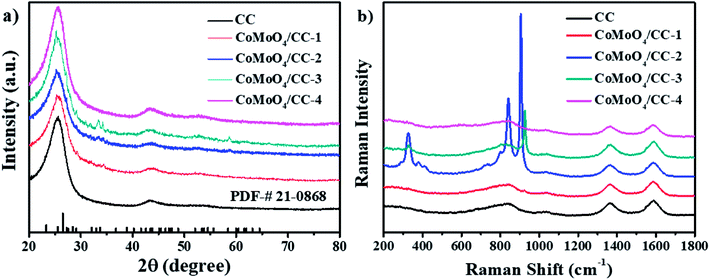 | ||
| Fig. 1 (a) XRD patterns (b) Raman spectra of the as-prepared CoMoO4/CC-n (n = 1, 2, 3 and 4) and raw carbon cloth. | ||
The XPS is also conducted to confirm the oxidation valence states of the CoMoO4/CC-2 composite. The full survey spectrum in Fig. 2a indicates the presence of the Mo, Co and O elements in the composite and the unequal atomic ratio of Co/Mo elements are listed in Table S2,† illustrating partial doping of Co element into the CoMoO4 composite. The deconvolution of the Co 2p spectrum in Fig. 2a shows two peaks, the peaks centred at 781.0 eV and 796.0 eV are related to the Co 2p3/2 and Co 2p1/2, respectively, which refer to Co2+ species.36 Moreover, the apparent satellite peaks of the Co 2p spectrum also verify the existence of the Co(II). For the Mo 3d spectrum (Fig. 2c), the binding energy located at 232.9 eV and 235.3 eV can be specified as Mo d5/2 and Mo d3/2 of the Mo6+ species, respectively, which is in line with the valance state of the MoO42− precursor.18,37 In the O 1s region (Fig. 2d), two peaks around 530.5 eV and 532.1 eV are corresponding to the Mo–O and Co–O, respectively.38,39 Therefore, the XPS results demonstrate the successful fabrication of the CoMoO4 materials on the carbon cloth.
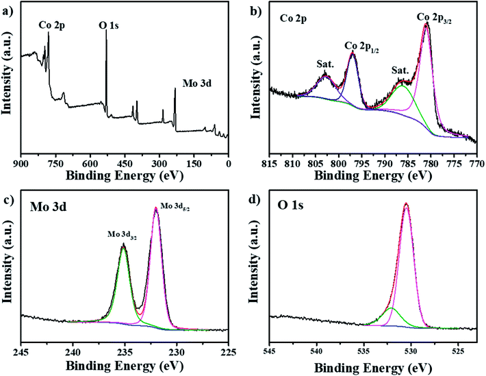 | ||
| Fig. 2 XPS spectra of (a) full survey, (b) Co 2p, (c) Mo 3d and (d) O 1s of the CoMoO4/CC-2 electrode. | ||
The morphology evolution and the microstructure of the CoMoO4/CC hybrids are investigated by SEM analysis. As shown in the low-magnification images (Fig. S2†), the hierarchical CoMoO4 architectures with different morphologies are uniformly and seamlessly anchored on the surface of the carbon cloth, further demonstrating the simple but effective large-scale active material coating strategy. The EDS images of the CoMoO4/CC-2 (Fig. 3e) illustrate all the elements (Co, Mo and O) are uniformly dispersed on the CC surface, indicating the uniform distribution of the CoMoO4 nanosheets. Under higher magnification (Fig. 3), the CoMoO4 architectures exhibit distinct morphology evolution with the increment of the Co/Mo ratio during hydrothermal process. The CoMoO4 architecture is constructed by the interconnected nanosheets with high porosity under lower Co/Mo ratio (1![[thin space (1/6-em)]](https://www.rsc.org/images/entities/char_2009.gif) :
:![[thin space (1/6-em)]](https://www.rsc.org/images/entities/char_2009.gif) 8, and 1
8, and 1![[thin space (1/6-em)]](https://www.rsc.org/images/entities/char_2009.gif) :
:![[thin space (1/6-em)]](https://www.rsc.org/images/entities/char_2009.gif) 4) (Fig. 3a and b), while the structure of the nanosheets turns from wrinkled and irregular structure of CoMoO4/CC-1 to more ideal nanosheets crystals of CoMoO4/CC-2. Moreover, with higher Co ions concentration, the thickness of the nanosheets increases from less than 10 nm to around 16 nm. Furthermore, the CoMoO4/CC-3 (Fig. 3c) displays the hybrid CoMoO4 nanostructure with both nanosheets and nanorods coexisted, while the nanosheets reveal increased plate size and thickness. When the Co/Mo ratio increased to a higher level of 1
4) (Fig. 3a and b), while the structure of the nanosheets turns from wrinkled and irregular structure of CoMoO4/CC-1 to more ideal nanosheets crystals of CoMoO4/CC-2. Moreover, with higher Co ions concentration, the thickness of the nanosheets increases from less than 10 nm to around 16 nm. Furthermore, the CoMoO4/CC-3 (Fig. 3c) displays the hybrid CoMoO4 nanostructure with both nanosheets and nanorods coexisted, while the nanosheets reveal increased plate size and thickness. When the Co/Mo ratio increased to a higher level of 1![[thin space (1/6-em)]](https://www.rsc.org/images/entities/char_2009.gif) :
:![[thin space (1/6-em)]](https://www.rsc.org/images/entities/char_2009.gif) 1 (Fig. 3d), the nanostructure of the CoMoO4 changed to nanorods arrays vertically aligned on the surface of the carbon cloth. The morphology evolution with the change of the Co/Mo ratio may be due to the shape-controlled effects of Co2+ during hydrothermal reaction: with the increment of the Co2+ concentration, the nuclei density of the CoMoO4 increases at the carbon cloth interface as well as in the solution, which further influences the growth rate and the crystalline structure of the nanostructures. Moreover, the contact interface of these electrodes may differ with the different CoMoO4 morphology and thickness, the larger contact interface may be beneficial to the electrons transfer rate from the carbon cloth to CoMoO4, thus influencing the active sites utilization efficiency.40
1 (Fig. 3d), the nanostructure of the CoMoO4 changed to nanorods arrays vertically aligned on the surface of the carbon cloth. The morphology evolution with the change of the Co/Mo ratio may be due to the shape-controlled effects of Co2+ during hydrothermal reaction: with the increment of the Co2+ concentration, the nuclei density of the CoMoO4 increases at the carbon cloth interface as well as in the solution, which further influences the growth rate and the crystalline structure of the nanostructures. Moreover, the contact interface of these electrodes may differ with the different CoMoO4 morphology and thickness, the larger contact interface may be beneficial to the electrons transfer rate from the carbon cloth to CoMoO4, thus influencing the active sites utilization efficiency.40
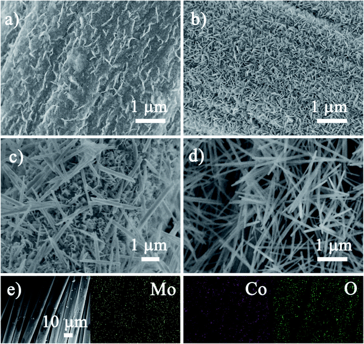 | ||
| Fig. 3 SEM images of the (a) CoMoO4/CC-1, (b) CoMoO4/CC-2 and (c) CoMoO4/CC-3 and (d) CoMoO4/CC-4, (e) the SEM image and corresponding elemental mapping of Mo, Co and O of the CoMoO4/CC-2. | ||
The surface morphology and crystalline feature of the CoMoO4/CC-2 composite is further confirmed by TEM test. As shown in Fig. 4a, the CoMoO4 nanosheets exhibit layered and quasi-hexagonal structure, indicating the relatively good crystalline structure of the nanosheets. The high resolution image in Fig. 4b illustrates the formation of mesoporous structures on the CoMoO4 nanosheets, which may result from the crystal defects of the nanosheets. These defective hexagonal structure and porous defects can provide sufficient active sites for the electrocatalytic reaction.41,42 Moreover, Fig. 4c reveals the defective polycrystalline structure of the as-prepared CoMoO4 nanosheets, and the lattice fringe of 0.26 nm can be related to the (−222) plane of CoMoO4. Moreover, the crystalline structure is further confirmed by the selected area electron diffraction (SAED) pattern (Fig. 4d), the (−222) plane is in line with the XRD results. Similar crystalline structure can also be observed from the TEM images of the CoMoO4/CC-3 composite (Fig. S3, see ESI†). Therefore, the CoMoO4/CC composites may act as the high-performance electrocatalytic electrode: the interconnected porous CoMoO4 nanocrystals with sufficient defects can provide sufficient active sites for electrochemical conversion reaction, while the 3D conductive struts and the tightly contact interface can facilitate the electrons transfer rate to ensure the utilization efficiency of the active sites.
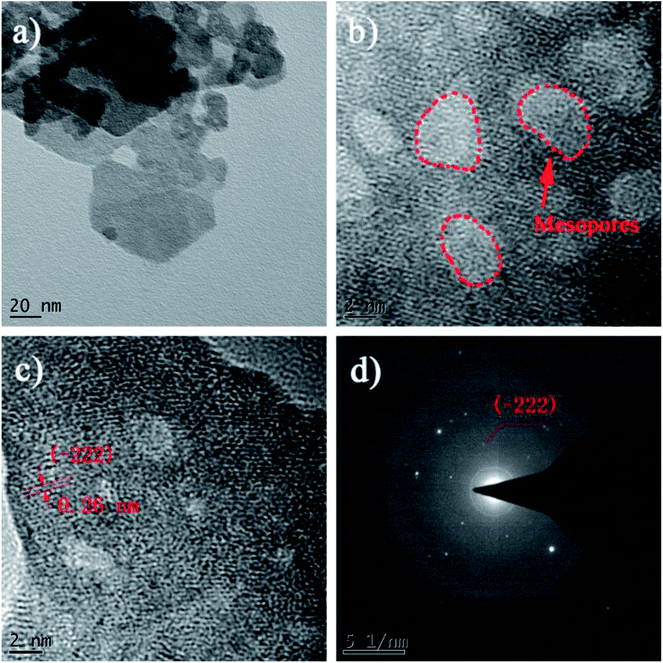 | ||
| Fig. 4 TEM images of the CoMoO4/CC-2 composite, (a) the CoMoO4 nanosheets, (b and c) the high-resolution image of the CoMoO4 nanosheets and (d) the SAED pattern acquired from CoMoO4 nanosheets. | ||
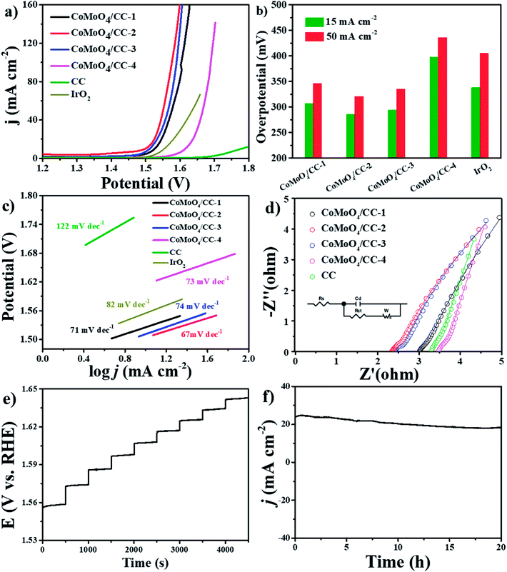
The three-electrode system is carried out to investigate the electrocatalytic OER performance of the composites. The LSV curves collected under 5 mV s−1 are shown in Fig. 5a. The CoMoO4/CC-2 electrode shows an overpotential of 286 mV at 15 mA cm−2, which is better than that of the CoMoO4/CC-1 (307 mV), CoMoO4/CC-3 (294 mV), CoMoO4/CC-4 (398 mV), CC scaffold and commercial IrO2 (339 mV). Moreover, this value is also better than or comparable with that of the state-of-the-art electrocatalysts (Table S3, see ESI†). Furthermore, the overpotential of the CoMoO4/CC-2 is still lower than that of the other CoMoO4/CC-n (n = 1, 3, 4) electrodes under higher response current density (Fig. 5b). Moreover, The Tafel slopes are calculated to be 71, 67, 74, 73, 122 and 82 mV dec−1 for CoMoO4/CC-1, CoMoO4/CC-2, CoMoO4/CC-3, CoMoO4/CC-4, CC and commercial IrO2, respectively (Fig. 5c). The earlier overpotential and smaller Tafel slope of the CoMoO4/CC-2 composite can be attributed to the improvement of the electrons transfer rate at the contact interface and increased active sites utilization efficiency.28 To gain insights into the activity improvement mechanism, the EIS results are presented in Fig. 5d. The CoMoO4/CC-2 electrode exhibits similar charge transfer resistance with that of the other composites in high frequency region, while the contact interface conductivity is improved clearly with the Rs 2.2 Ω from the equivalent circuit, which is in accordance with OER catalytic performance. The multi-current responding curve in Fig. 5e reveals the potential stabilized at 1.558 V under 10 mA cm−2 and similar results remain unchanged at all other steps, illustrating the good conductivity, mass transportation property and mechanical robustness of the 3D CoMoO4/CC-2 electrode.43,44 Moreover, the long-term stability of the CoMoO4/CC-2 composites is evaluated by applying a constant potential (1.6 V vs. RHE) on the electrode for 20 h (Fig. 5f). The constant response current density during the period indicates good electrocatalytic stability of the CoMoO4/CC-2 composites.45 Furthermore, the SEM, XRD, XPS and TEM results of the CoMoO4/CC-2 electrode after the long-term catalytic test also reveal the superior structural and crystalline stability of the nanosheets (Fig. 6 and S4–S6, see ESI†).
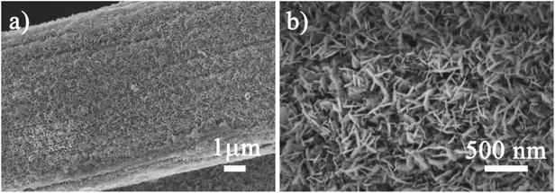 | ||
| Fig. 6 (a) The low-magnification and (b) low-magnification SEM images of the CoMoO4/CC-2 electrode after long-term catalytic stability test. | ||
To estimate the ECSA of the electrodes and understand the relationship between the active material crystal structure and OER activity, the CV tests are conducted in the region of 1.276 to 1.376 V vs. RHE under different scan rates (Fig. 7a and S7†). As the response current density should only be relevant to the electrical double layer surface area (Cdl), thus the ECSA of the electrodes can be calculated.46 The CoMoO4/CC-2 sample shows a highest Cdl of 70.2 mF cm−2 (Fig. 7b), which is larger than those of the CoMoO4/CC-1 (67.1 mF cm−2), CoMoO4/CC-3 (39.7 mF cm−2) and CoMoO4/CC-4 (15.0 mF cm−2). The highest Cdl of the CoMoO4/CC-2 hybrid suggests the enlarged electrocatalytic surface area, thus active sites utilization efficiency of the active material in the catalytic process is also largely increased.47,48
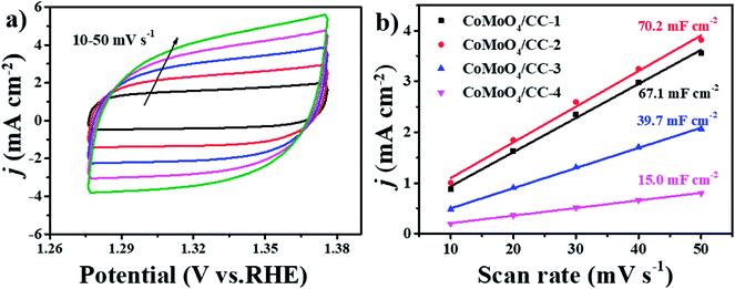 | ||
| Fig. 7 (a) CV curves of the CoMoO4/CC-2 at different scan rates from 10 to 50 mV s−1, (b) estimated Cdl and relative electrochemically active surface area of the CoMoO4/CC-n electrodes. | ||
4. Conclusion
In summary, the three-dimensional (3D) free-standing CoMoO4 nanoarrays with different morphologies anchored on the carbon cloth were synthesized via a one-pot hydrothermal method without post heat treatment. The CoMoO4 morphology evolution with the change of the Co/Mo precursor ratio and the materials contact interface is investigated. As the OER electrode, the CoMoO4/CC-2 composite with interconnected nanosheets reveals superior catalytic activity, the overpotential of 286 mV at 15 mA cm−2 and Tafel slope of 67 mV dec−1 can be obtained. Moreover, the CoMoO4/CC-2 electrode shows high long-term electrochemical and structural stability. As the carbon cloth is commercially available, this simple but effective morphology controlling method can act as a new large-scale practical electrode fabrication technique for large-scale water splitting.Conflicts of interest
There are no conflicts to declare.Acknowledgements
We appreciate the financially supported by the National Natural Science Foundation of China (21776187, 21490582, 21506130), the State Key Laboratory of Polymer Materials Engineering (Grant No. sklpme2017-3-01) and the Fundamental Research Funds for the Central Universities.References
- M. Armand and J. M. Tarascon, Nature, 2008, 451, 652–657 CrossRef CAS PubMed.
- J. Ji, Y. Li, W. Peng, G. Zhang, F. Zhang and X. Fan, Adv. Mater., 2015, 27, 5264–5279 CrossRef CAS PubMed.
- N.-T. Suen, S.-F. Hung, Q. Quan, N. Zhang, Y.-J. Xu and H. M. Chen, Chem. Soc. Rev., 2017, 46, 337–365 RSC.
- X. Cui, Y. Zhu, F. Li, D. Liu, J. Chen, Y. Zhang, L. L. Zhang and J. Ji, RSC Adv., 2016, 6, 9007–9012 RSC.
- I. Yoshikazu, O. Tatsuhiko, H. Daisuke, W. Mitsuru, N. Yuki, C. Linghan, H. Kailong, I. Masahiko, F. Jun-ichi and A. Tadafumi, ACS Catal., 2018, 8, 3579–3586 CrossRef.
- Z. Chen, Y. Song, J. Cai, X. Zheng, D. Han, Y. Wu, Y. Zang, S. Niu, Y. Liu, J. Zhu, X. Liu and G. Wang, Angew. Chem., Int. Ed., 2018, 57, 5076–5080 CrossRef CAS.
- X. Guo, J. Ji, Q. Jiang, L. Zhang, Z. Ao, X. Fan, S. Wang, Y. Li, F. Zhang, G. Zhang and W. Peng, ACS Appl. Mater. Interfaces, 2017, 9, 30591–30598 CrossRef CAS PubMed.
- F. Wang, Y. Zhu, W. Tian, X. Lv, H. Zhang, Z. Hu, Y. Zhang, J. Ji and W. Jiang, J. Mater. Chem. A, 2018, 6, 10490–10496 RSC.
- Z. Chen, L. Cai, X. Yang, K. Coleman, L. Guo, S. Shen and E. K. Bruce, ACS Catal., 2018, 8, 1238–1247 CrossRef CAS.
- F. Qin, Z. Zhao, M. K. Alam, Y. Ni, F. C. R. Hernandez, L. Yu, S. Chen, Z. Ren, Z. Wang and J. Bao, ACS Energy Lett., 2018, 3, 546–554 CrossRef CAS.
- M. Tahir, L. Pan, F. Idrees, X. Zhang, L. Wang, J.-J. Zou and Z. L. Wang, Nano Energy, 2017, 37, 136–157 CrossRef CAS.
- Y. Lee, J. Suntivich, K. J. May, E. E. Perry and S. H. Yang, J. Phys. Chem. Lett., 2012, 3, 399–404 CrossRef CAS PubMed.
- C. C. L. McCrory, S. Jung, J. C. Peters and T. F. Jaramillo, J. Am. Chem. Soc., 2013, 135, 16977–16987 CrossRef CAS PubMed.
- X. Lv, Y. Zhu, T. Yang, H. Zhang, X. Cui, H. Yue, D. Liu, J. Chen and J. Ji, Ceram. Int., 2016, 42, 19006–19011 CrossRef CAS.
- H. Zhang, X. Lv, F. Wang, H. Zhufen, H. Han, X. Fan and J. Ji, Ceram. Int., 2018, 44, 7611–7617 CrossRef CAS.
- Y. Wang, T. Zhou, K. Jiang, P. Da, Z. Peng, J. Tang, B. Kong, W. Cai, Z. Yang and G. Zheng, Adv. Energy Mater., 2014, 4, 1400696 CrossRef.
- X. Liu, W. Xi, C. Li, X. Li, J. Shi, Y. Shen, J. He, L. Zhang, L. Xie, X. Sun, P. Wang, J. Luo, L. Liu and Y. Ding, Nano Energy, 2018, 44, 371–377 CrossRef CAS.
- J. Zhao, X. Ren, H. Ma, X. Sun, Y. Zhang, T. Yan, Q. Wei and D. Wu, ACS Sustainable Chem. Eng., 2017, 5, 10093–10098 CrossRef CAS.
- L. Fang, F. Wang, T. Zhai, Y. Qiu, M. Lan, K. Huang and Q. Jing, Electrochim. Acta, 2018, 259, 552–558 CrossRef CAS.
- Y. Huang, X. Zhao, F. Tang, X. Zheng, W. Cheng, W. Che, F.-C. Hu, Y. Jiang, Q. Liu and S. Wei, J. Mater. Chem. A, 2018, 6, 3202–3210 RSC.
- S. Ye, Z. Shi, J. Feng, Y. Tong and G. Li, Angew. Chem., Int. Ed., 2018, 57, 1–6 CrossRef.
- J. Qian, Z. Li, X. Guo, Y. Li, W. Peng, G. Zhang, F. Zhang and X. Fan, Ind. Eng. Chem. Res., 2018, 57, 483–489 CrossRef CAS.
- J. Meng, J.-Q. Fu, X. Yang, M.-J. Wei, S. Liang, H.-Y. Zang, H.-Q. Tan, Y.-H. Wang and Y.-G. Li, Inorg. Chem. Front., 2017, 4, 1791–1797 RSC.
- J. Ji, J. Liu, L. Lai, X. Zhao, Y. Zhen, J. Lin, Y. Zhu, H. Ji, L. L. Zhang and R. S. Ruoff, ACS Nano, 2015, 9, 8609–8616 CrossRef CAS PubMed.
- K. Chi, Z. Zhang, Q. Lv, C. Xie, J. Xiao, F. Xiao and S. Wang, ACS Appl. Mater. Interfaces, 2017, 9, 6044–6053 CrossRef CAS PubMed.
- Y. Li, H. Xu, H. Huang, C. Wang, L. Gao and T. Ma, Chem. Commun., 2018, 54, 2739–2742 RSC.
- F. Wang, X. Lv, L. Zhang, H. Zhang, Y. Zhu, Z. Hu, Y. Zhang, J. Ji and W. Jiang, J. Power Sources, 2018, 393, 169–176 CrossRef CAS.
- K. Yan, J. Qin, Z. Liu, B. Dong, J. Chi, W. Gao, J. Lin, Y. Chai and C. Liu, Chem. Eng. J., 2018, 334, 922–931 CrossRef CAS.
- Y. Zhu, F. Wang, H. Zhang, X. Lv, Z. Hu, H. Han, X. Fan, J. Ji and X. Guo, J. Alloys Compd., 2018, 747, 276–282 CrossRef CAS.
- Z. Tong, D. Yang, X. Zhao, J. Shi, F. Ding, X. Zou and Z. Jiang, Chem. Eng. J., 2018, 337, 312–321 CrossRef CAS.
- H. Huang, C. Yu, X. Han, S. Li, S. Cui, C. Zhao, H. Huang and J. Qiu, Ind. Eng. Chem. Res., 2017, 56, 14245–14251 CrossRef CAS.
- L. Wang, H. Yang, X. Liu, R. Zeng, M. Li, Y. Huang and X. Hu, Angew. Chem., Int. Ed. Engl., 2017, 56, 1105–1110 CrossRef CAS PubMed.
- L. Mai, F. Yang, Y. Zhao, X. Xu, L. Xu and Y. Luo, Nat. Commun., 2011, 2, 381–386 CrossRef PubMed.
- G. K. Veerasubramani, K. Krishnamoorthy and S. J. Kim, J. Power Sources, 2016, 306, 378–386 CrossRef CAS.
- A. P. d. Moura, L. H. d. Oliveira, P. F. S. Pereira, I. L. V. Rosa, M. S. Li, E. Longo and J. A. Varela, Adv. Chem. Eng. Sci., 2012, 02, 465–473 CrossRef.
- P. Wu, S. Cheng, M. Yao, L. Yang, Y. Zhu, P. Liu, O. Xing, J. Zhou, M. Wang, H. Luo and M. Liu, Adv. Funct. Mater., 2017, 27, 1702160 CrossRef.
- Z. Lv, M. Tahir, X. Lang, G. Yuan, L. Pan, X. Zhang and J. Zou, J. Mater. Chem. A, 2017, 5, 20932–20937 RSC.
- B. Ren, D. Li, Q. Jin, H. Cui and C. Wang, J. Mater. Chem. A, 2017, 5, 24453–24461 RSC.
- R. Wei, M. Fang, G. Dong, C. Lan, L. Shu, H. Zhang, X. Bu and J. C. Ho, ACS Appl. Mater. Interfaces, 2018, 10, 7079–7086 CrossRef CAS PubMed.
- X. Lv, H. Zhang, F. Wang, Z. Hu, Y. Zhang, L. Zhang, R. Xie and J. Ji, CrystEngComm, 2018, 20, 1690–1697 RSC.
- Z. Liu, Z. Zhao, Y. Wang, S. Dou, D. Yan, D. Liu, Z. Xia and S. Wang, Adv. Mater., 2017, 29, 1606207 CrossRef PubMed.
- Y. Wang, T. Li, Z. Xiao, R. Chen, Z. Jiang and S. Wang, Adv. Funct. Mater., 2018, 28, 1705356 CrossRef.
- M. Xie, L. Yang, Y. Ji, Z. Wang, X. Ren, Z. Liu, A. M. Asiri, X. Xiong and X. Sun, Nanoscale, 2017, 9, 16612–16615 RSC.
- Y. Wei, X. Ren, H. Ma, X. Sun, Y. Zhang, X. Kuang, T. Yan, H. Ju, D. Wu and Q. Wei, Chem. Commun., 2018, 54, 1533–1536 RSC.
- X. Ren, R. Ge, Y. Zhang, D. Liu, D. Wu, X. Sun, B. Du and Q. Wei, J. Mater. Chem. A, 2017, 5, 7291–7294 RSC.
- S. Trasatti and O. A. Petrii, J. Electroanal. Chem., 1992, 327, 353–376 CrossRef CAS.
- D. Wu, Y. Wei, X. Ren, X. Ji, Y. Liu, X. Guo, Z. Liu, A. M. Asiri, Q. Wei and X. Sun, Adv. Mater., 2018, 30, 1705366 CrossRef PubMed.
- X. Ren, X. Ji, Y. Wei, D. Wu, Y. Zhang, M. Ma, Z. Liu, A. M. Asiri, Q. Wei and X. Sun, Chem. Commun., 2018, 54, 1425–1428 RSC.
Footnotes |
| † Electronic supplementary information (ESI) available: SEM images, XRD patterns, XPS spectrums and TEM images of the CoMoO4/CC composites before and after long term catalytic stability test, and the CV curves of composites collected under different scan rates are listed. See DOI: 10.1039/c8ra09484e |
| ‡ The authors contribute equal to this manuscript. |
| This journal is © The Royal Society of Chemistry 2019 |

