 Open Access Article
Green synthesis of a AgCl@AgI nanocomposite using Laminaria japonica extract and its application as a visible-light-driven photocatalyst†
Zhongyu Ruan‡
a,
Guihong Liu‡a,
Jinxia Shua,
Chunguang Ren*b and
Zhonghua Wang *a
*a
aChemical Synthesis and Pollution Control Key Laboratory of Sichuan Province, College of Chemistry and Chemical Engineering, China West Normal University, Nanchong, Sichuan 637002, P. R. China. E-mail: zhwangs@163.com
bYantai Institute of Materia Medica, 39 Keji Road, Gaoxin District, Yantai 264000, Shandong, P. R. China. E-mail: cgren@simmyt.ac.cn
First published on 18th February 2019
Abstract
A AgCl@AgI composite photocatalyst was greenly synthesized using Laminaria japonica extract as the source of halogen anions, and characterized by XRD, SEM, TEM and XPS techniques. The photocatalytic activity and photochemical stability of the AgCl@AgI were investigated by the photodegradation of methyl orange (MO) azo dye under visible light illumination (λ > 420 nm). The AgCl@AgI composite showed good photochemical stability and much higher photocatalytic activity than that of single AgCl and AgI. Mechanism studies showed that the main active species are photoinduced holes (h+) and superoxide anion radicals (·O2−). Finally, a plausible mechanism for the separation of photoinduced charge carriers was proposed.
1. Introduction
Semiconductor-based photocatalytic oxidation processes under UV/visible light irradiation is a promising wastewater treatment method because it can effectively destroy many organic pollutants that are stable and non-biodegradable.1–4 Up to now, a variety of semiconductors have been fabricated and investigated for wastewater treatment.5–9 TiO2 and ZnO are the most widely studied photocatalysts due to their low cost, non-toxicity, high efficiency and good stability.10–13 Both TiO2 and ZnO have a large bandgap (3.0–3.2 eV)11–13 and only respond to UV light which occupies about 5% of the solar spectrum. This drawback of large bandgap semiconductors greatly restricts their practical applications.14 Therefore, it is essential and urgent to develop new photocatalysts that can respond to visible light irradiation.Recent decade, a new type of Ag-based materials, especially silver halides (AgX, X= Cl, Br and I) have been developed as photocatalysts for the degradation of organic pollutants.15–17 Among AgX compounds, AgCl has received great attention in photocatalytic field due to its stability and effective photocatalytic performance.16–19 However, just like TiO2 and ZnO, AgCl cannot adsorb visible light since the wide bandgap of 3.25 eV.20 One of the strategies to overcome this drawback is to combine with other materials. With the attempt to extend the absorption edge of AgCl to visible light region and reduce the recombination of electron–hole pairs simultaneously, many studies have been made by couple AgCl with other Ag-based materials.21,22 For example, Gu and co-workers prepared AgCl/Ag3PO4 complex photocatalyst by a facile ion-exchange technology and found that the hybrid microstructure showed enhanced photocatalytic performance than the single Ag3PO4 and AgCl catalysts.21 Yu and co-workers prepared AgCl@Ag2CO3 heterostructured photocatalyst by a co-precipitation method and found that the formation of AgCl/Ag2CO3 heterostructure could effectively suppress the recombination of photogenerated electron and hole pairs, resulting in an increase in photocatalytic activity.22
Much attentions have been paid to green synthesis over the past decade with the increasing awareness of environmental issues.23 Utilization of bio-organisms, especially plants that secrete the functional molecules for the reaction, is in accordance with green synthesis principles.24 Some nanomaterials have been synthesized using plants. For instance, Ag and Pd nanocrystals have been synthesized using coffee and tea extract,25 CaCO3 crystals have been synthesized by the reaction of calcium ions with germinating chickpea seeds.26 Recently, several photocatalytic materials have also been obtained by green synthetic method. AgCl@Ag nanoparticles have been synthesized using sugar cane juice,27 Au@Ag@AgCl hybrid nanoparticles have been synthesized using Aquilaria agallocha leaf juice,28 sphere-shaped Ag–SnO2 nanocomposites have been fabricated by employing the stem extracts of Saccharum officinarum.29
Laminaria japonica is highly appreciated and widely used as a food source in Far East Asia, especially in China, Japan and Korea.30 It is inexpensive, nontoxic, and is available easily in supermarkets. Laminaria japonica is rich in proteins, vitamins and minerals, especially very rich in iodine.31 In this work, we synthesized AgCl@AgI nanocomposite by a facile green synthesis method with Laminaria japonica extract as halogen anions sources (I− and Cl−). The photocatalytic activity of the AgCl@AgI composite was evaluated by the photodegradation of methyl orange (MO) under visible light illumination. The photocatalytic activity of AgCl@AgI was remarkably higher than that of single AgCl and AgI. In addition, the AgCl@AgI composite photocatalyst showed good stability under visible light irradiation. Mechanism studies showed that the main active species were superoxide radicals and photogenerated holes.
2. Experimental section
2.1 Preparation of Laminaria japonica extract
Laminaria japonica was purchased in a dried state from a local supermarket. First, the Laminaria japonica sample was cleaned with a brush and cut into small pieces, and then 20 g of Laminaria japonica pieces was put into a ceramic crucible, covered with a lid, and heated at 300 °C for 1 h in a muffle furnace. After cooled down to room temperature naturally, the resulting product was ground into powder in a mortar. The powder was dispersed and extracted three times by using 20, 20, and 10 mL deionized water under mild stirring and heating conditions. After filtration, the extracting solution was collected and kept at ∼10 °C in a refrigerator before the following synthesis.2.2 Synthesis of AgCl@AgI nanocomposite
In a typical synthesis, 20 mL of AgNO3 (0.1 M) was added dropwise into 40 mL Laminaria japonica extract, and magnetically stirred for 30 min. The AgCl@AgI composite precipitate was separated by centrifugation, and the supernatant was collected for the preparation of AgCl as stated below. The separated AgCl@AgI precipitate was washed with deionized water, and then dried at 60 °C in an electric dry oven.After the separation of AgCl@AgI precipitate, the collected supernatant was used for the preparation of AgCl as following: 20 mL of AgNO3 (0.1 M) was added into the above mentioned supernatant for the preparation of AgCl. AgI was prepared by the addition of 5 mL AgNO3 (0.1 M) to 40 mL of Laminaria japonica extract solution. The separation, washing and drying steps were the same as that of AgCl@AgI.
2.3 Characterization
The phase structure of the AgCl@AgI sample was measured by a powder X-ray diffractometer (Rigaku Dmax/Ultima IV) equipped with monochromatized Cu Kα radiation (λ = 1.5418 Å). The morphologies were performed on a JEOL JSM-6510LV scanning electron microscope and an FEI Tecnai F20 transmission electron microscope. The surface elemental composition and chemical status were determined on a Thermo-Fisher K-Alpha X-ray photoelectron spectroscope with Al Kα excitation.2.4 Photocatalytic activity
The visible light photocatalytic activity of the AgCl@AgI composite was examined by the photodegradation of methyl orange (MO) azo dye under the illumination of a 70 W metal halide lamp.17 During the illumination, a 420 nm ultraviolet cutoff filter was used to remove the UV light with wavelength less than 420 nm. The photocatalytic reaction was performed by dispersing 100 mg AgCl@AgI composite into 50 mL of 10 mg L−1 MO solution. Before light illumination, the mixture was stirred magnetically for 30 min to achieve an absorption–desorption equilibrium. At given time intervals, about 3 mL aliquots were sampled and the AgCl@AgI composite was removed by a 0.45 μm membrane filter or by centrifugation before concentration measurement. The concentration of remnant MO in the solution was determined spectroscopically using a Shimadzu UV-2550 spectrophotometer at the wavelength of 464 nm.2.5 Photcatalytic mechanism
For active species trapping experiment, 10 mM isopropyl alcohol (IPA) and 10 mM ammonium oxalate (AO) were added to the MO solution as the scavengers of hydroxyl radicals (·OH−) and photoinduced holes (h+), respectively. 0.2 mM p-benzoquinone (BQ) were used as superoxide radicals (·O2−) scavenger. The trapping experiments were performed with the similar procedure as the photodegradation of MO except to the addition of selected scavengers.Photodegradation of MO under deaerated conditions was carried out according to previously reported method.32 Hydroxyl radicals (·OH) were monitored by using terephthalic acid (TA) as a fluorescence probe.32 The concentration of TA was 0.5 mM in 1.5 mM NaOH solution. The sampling solution was removed every 4 min and filtered with a 0.45 μm membrane filter for fluorescence spectroscopy measurement. The excitation light wavelength used for recording the fluorescence spectra of 2-hydroxy terephthalic acid (TA-OH) was 315 nm. The reference experiment using TiO2 as a UV light response photocatalyst was performed as previous reports.32,33
3. Results and discussion
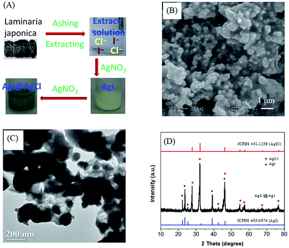
The preparation process of AgCl@AgI composite using Laminaria japonica extract was shown in Fig. 1A. With the addition of AgNO3 solution, a yellow precipitate was firstly formed, indicating the generation of AgI. Then the precipitate turned brown and green by the formation of AgCl@AgI composite. The SEM and TEM images showed that the morphology of AgCl@AgI composite was irregular with diameter in the range of 100–300 nm (Fig. 1B and C). The irregular particles were connected to each other with cotton-like sheets (Fig. 1C). In addition, HRTEM showed that there was an interface between AgCl and AgI (Fig. S1†). Fig. 1D shows the XRD patterns of the AgCl@AgI sample. Two sets of XRD diffraction peaks were observed. The diffraction peaks at 2θ values of about 27.7°, 32.1°, 46.2°, 54.8°, 57.4°, 67.3° and 76.6° were assigned to the (111), (200), (220), (311), (222), (400) and (420) planes of cubic phase AgCl34 (denoted with red , JCPDS No. 31-1238). While the diffraction peaks at 2θ values of about 22.3°, 23.7°, 25.3°, 39.2°, 42.7° and 46.2° were indexed to the (100), (002), (101), (110), (103) and (112) planes of β phase AgI32,35 (denoted with black
  , JCPDS No. 09-0374). It's worth of pointing out that the peak at 46.2° should be due to the overlap of AgCl (220) and AgI (112) planes and the diffraction peaks corresponding to metal silver (Ag) was not observed in the XRD patterns of AgCl@AgI sample.
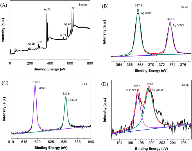
The X-ray photoelectron spectroscopy (XPS) studies showed that the AgCl@AgI composite contained chloride (Cl), iodine (I), silver (Ag), and carbon (C) elements as revealed by the survey XPS spectrum (Fig. 2A). The carbon element was ascribed to the adventitious hydrocarbons from the XPS instrument itself.36 While the Ag, Cl and I peaks were from the AgCl@AgI composite sample. According to the XPS analysis, the mole ratio of AgCl to AgI was determined to be 1.8![[thin space (1/6-em)]](https://www.rsc.org/images/entities/char_2009.gif) :
:![[thin space (1/6-em)]](https://www.rsc.org/images/entities/char_2009.gif) 1.
1.
Fig. 2B shows the high-resolution XPS spectrum of Ag 3d, the peaks appeared at binding energy (BE) of 367.6 and 373.6 eV were ascribed to Ag 3d5/2 and Ag 3d3/2, respectively. The two peaks at BE of 619.1 and 630.6 eV in the high-resolution XPS spectrum of iodine could be assigned to I 3d5/2 and I 3d3/2 respectively (Fig. 2C). The peaks for Cl 2p3/2 and Cl 2p1/2 were observed at BE of 197.5 and 199.5 eV, respectively (Fig. 2D).
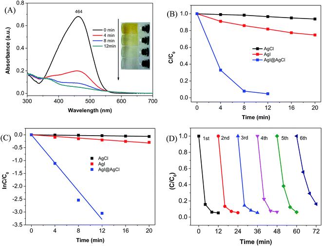
The photocatalytic activity of the AgCl@AgI composite was evaluated by the photodegradation of methyl orange (MO). Fig. 3A shows the UV-visible spectral changes of MO solution under visible light (λ > 420 nm) irradiation in the presence of AgCl@AgI composite photocatalyst. It could be seen that the absorption at 464 nm obviously decreased with irradiation time. Simultaneously, the color of the MO solution changed from orange yellow to near colorless (Fig. 3A, inset). The degradation percentage of MO was more than 95% after 12 min of photocatalytic reaction. For comparison, the degradation of MO in the presence of single AgCl or AgI was also performed. But only 6% and 25% of MO was degraded with 20 min of light illumination in the presence of AgCl and AgI, respectively (Fig. S2† and 3B). Furthermore, the preparation of AgCl@AgI composite by conventional method (AgCl@AgI-CM) and its photocatalytic activity was also performed. Results showed that only 60% of MO was degraded in the presence of AgCl@AgI-CM photocatalyst, which was much lower than that of AgCl@AgI prepared with Laminaria japonica extract (ESI and Fig. S3†).
To further evaluate the catalytic activity of the AgCl@AgI photocatalyst, we estimated the rate constants from the plots of ln(C/C0) vs. time (Fig. 3C), assuming that the MO degradation reaction followed pseudo-first order kinetics (dC/dt = kC), where C and C0 are the concentrations of MO solutions before (t = 0) and after visible light irradiation for a centain time (t = t), respectively. The rate constant for AgCl@AgI composite was estimated to be 0.274 min−1, which was about 88 and 17-fold higher than that of AgCl (0.0031 min−1) and AgI (0.016 min−1), respectively. These results indicated that the photocatalytic activity of AgCl@AgI was remarkably enhanced by the combination of AgCl and AgI.
Moreover, to examine the photochemical stability of the AgCl@AgI composite, the photocatalyst was recycled and reutilized for the photodegradation of MO. The photocatalytic activity of the AgCl@AgI composite did not change significantly within the first three cycles of reutilization (Fig. 3D), indicating the relative high photochemical stability of the AgCl@AgI composite. However, the degradation efficiency of MO began to decrease from the fourth to sixth cycle of reutilization. One of the reason should be due to the loss of the AgCl@AgI photocatalyst during the recovery process. Another reason might be ascribed to the inactivation of the photocatalyst. Because Ag-base materials are sensitive to light irradiation, and metallic silver (Ag) will be formed on the surface of Ag-based materials.16,17 To study the formation of metallic silver, we performed the XRD measurement of AgCl@AgI composite after light irradiation. It could be seen that a weak peak at 2θ value of about 38.2° appeared after the fourth cycle of reutilization, and this peak was obviously enhanced after the sixth cycle of reutilization (Fig. S4†). The peak at 2θ value of 38.2° in the XRD patterns could be attributed to the (111) planes of cubic phase silver (JCPDS No. 65-2871).17,18,37 These results indicated that after reutilization, Ag was formed and covered on the surface of AgCl@AgI composite, and consequently influenced the light absorption, charge separation and photocatalytic activity of the AgCl@AgI photocatalyst.
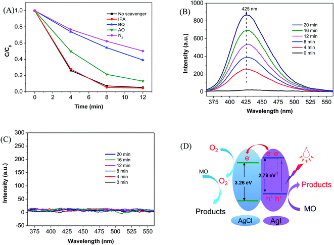
Mechanism study was performed by trapping experiment12,38 and terephthalic acid-based fluorescence technique.32 As shown in Fig. 3A, when IPA was added as the scavenger of hydroxyl radicals (·OH), the degradation of MO was not affected, indicating that ·OH might not be generated under visible light illumination in the presence of AgCl@AgI composite. The minor role of ·OH was further confirmed by terephthalic acid-based fluorescence technique.32 The emission wavelength at ∼425 nm gradually increased with time in the presence of P25 under UV light irradiation (Fig. 4B), indicating the production of 2-hydroxy terephthalic acid (TA-OH) which was generated by the reaction of terephthalic acid with ·OH. However, the fluorescence peak at 425 nm was not observed in the presence of AgCl@AgI photocatalyst under visible light irradiation (Fig. 4C), suggesting that ·OH was not generated in the presence of AgCl@AgI composite under visible light irradiation.
Contrary to addition of IPA, the degradation of MO was obviously inhibited when AO and BQ were added as the scavengers of photoinduced holes (h+) and superoxide anion radicals (·O2−). It has been widely accepted that ·O2− was generated by the reaction of oxygen (O2) with photoinduced electrons (e−). Hence the removal of O2 from the reaction solution should reduce the generation of ·O2−, and consequently inhibited the decomposition of MO. As expected, the degradation of MO was significantly influenced by the removal of O2 with N2 bubbling. These results implied that ·OH played minor role and the photoinduced h+ and ·O2− were the major active species in the photodegradation process of MO.
According to the above trapping experiments, we proposed a possible mechanism for the photogeneration of electron–hole pairs and the degradation of MO molecules (Fig. 4D). Upon visible light illumination, the photoinduced electrons (e−) in the valence band (VB) of AgI was excited to the conduction band (CB) and left the same amount of holes (h+) in the VB (eqn (1)) of AgI due to the narrow band gap of 2.8 eV.39 The photoexcited e− in the CB of AgI jumped into the CB of AgCl (eqn (2)), and subsequently captured by dissolved O2 to produce ·O2− (eqn (3)). The produced ·O2− can execute the oxidation of MO molecules (eqn (4)). Moreover, the photoinduce h+ in the VB of AgI could also oxidized MO directly (eqn (5)). The transfer of electrons from the CB of AgI to the CB of AgCl and the capture of electrons by molecule oxygen hinders the recombination of photoinduced charge carries, producing more active species (such as ·O2− and h+), and enhancing the photocatalytic activity of the composite photocatalyst.
| AgI + hν → h(AgI)+ + e(AgI)− | (1) |
| e(AgI)− + AgCl → e(AgCl)− | (2) |
| e(AgCl)− + O2 →·O2− | (3) |
| MO + ·O2− → products | (4) |
| MO + h+ → products | (5) |
4. Conclusions
In summary, AgCl@AgI nanocomposite was greenly synthesized by the reaction of Laminaria japonica extract with AgNO3 without the using of any other external chemicals. The photocatalytic activity of the AgCl@AgI composite was much higher than that of single AgI or AgCl due to the facile separation of charge carries. The AgCl@AgI composite also showed high stability, which was beneficial for practical applications in environmental remediation.Conflicts of interest
There are no conflicts of interest to declare.Acknowledgements
This work was supported by the University Student's Project of Innovation in science and technology at China West Normal University (Project No. 427298 (Z. Ruan)), and the Open Project of Chemical Synthesis and Pollution Control Key Laboratory of Sichuan Province (CSPC2016-3-2).Notes and references
- E. J. Wolfrum, J. Huang, D. M. Blake, P. C. Maness, Z. Huang, J. Fiest and W. A. Jacoby, Environ. Sci. Technol., 2002, 36, 3412–3419 CrossRef CAS.
- J. Y. Li, X. A. Dong, Y. J. Sun, W. L. Cen and F. Dong, Appl. Catal., B, 2018, 226, 269–277 CrossRef CAS.
- H. Wang, W. D. Zhang, X. W. Li, J. Y. Li, W. L. Cen, Q. Y. Li and F. Dong, Appl. Catal., B, 2018, 225, 218–227 CrossRef CAS.
- Y. C. Yu, C. J. Li, S. S. Huang, Z. J. Hu, Z. W. Chen and H. W. Gao, RSC Adv., 2018, 8, 32368–32376 RSC.
- L. Zhang, W. Tian, Y. Chen, J. Chen, H. C. Teng, J. C. Zhou, J. W. Shi and Y. M. Sun, RSC Adv., 2016, 6, 83471–83481 RSC.
- W. J. Ong, L. L. Tan, Y. H. Ng, S. T. Yong and S. P. Chai, Chem. Rev., 2016, 116, 7159–7329 CrossRef CAS PubMed.
- K. Nakata and A. Fujishima, J. Photochem. Photobiol., C, 2012, 13, 169–189 CrossRef CAS.
- J. P. Wang, Z. Y. Wang, B. B. Huang, Y. D. Ma, Y. Y. Liu, X. Y. Qin, X. Y. Zhang and Y. Dai, ACS Appl. Mater. Interfaces, 2012, 4, 4024–4030 CrossRef CAS PubMed.
- X. A. Dong, W. D. Zhang, Y. J. Sun, J. Y. Li, W. L. Cen, Z. H. Cui, H. W. Huang and F. Dong, J. Catal., 2018, 357, 41–50 CrossRef.
- R. C. Pawar and C. S. Lee, Appl. Catal., B, 2014, 144, 57–65 CrossRef CAS.
- Y. X. Li, C. F. Xie, S. Q. Peng, G. W. Lu and S. B. Li, J. Mol. Catal. Chem., 2008, 282, 117–123 CrossRef CAS.
- H. L. Jiang, J. Liu, M. L. Li, L. Tian, G. S. Ding, P. H. Chen and X. B. Luo, Chin. J. Catal., 2018, 39, 747–759 CrossRef CAS.
- Z. F. Tong, L. L. He, C. G. Ren, Z. H. Wang and Z. L. Jiang, Mater. Lett., 2018, 217, 296–299 CrossRef CAS.
- L. Hao, S. J. Guan, S. Takaya, H. Yoshida, M. Tochihara and Y. Lu, Appl. Surf. Sci., 2017, 407, 276–281 CrossRef CAS.
- H. G. Yu, W. Y. Chen, X. F. Wang, Y. Xu and J. G. Yu, Appl. Catal., B, 2016, 187, 163–170 CrossRef CAS.
- P. Wang, B. B. Huang, X. Y. Qin, X. Y. Zhang, Y. Dai, J. Y. Wei and M. H. Whangbo, Angew. Chem., Int. Ed., 2008, 47, 7931–7933 CrossRef CAS PubMed.
- J. Shu, Z. Wang, G. Xia, Y. Zheng, L. Yang and W. Zhang, Chem. Eng. J., 2014, 252, 374–381 CrossRef CAS.
- L. Xia, X. H. Jiang, Z. J. Cheng, Y. W. Liao, Z. H. Wang, Q. Pu and M. Duan, Mater. Chem. Phys., 2018, 218, 98–107 CrossRef CAS.
- P. Wang, C. D. Yu, J. J. Ding, X. F. Wang and H. G. Yu, J. Alloys Compd., 2018, 752, 238–246 CrossRef CAS.
- X. F. Wang, S. F. Li, Y. Q. Ma, H. G. Yu and J. G. Yu, J. Phys. Chem. C, 2011, 115, 14648–14655 CrossRef CAS.
- X.-q. Gu, S. Zhang, B. Wang and Y.-h. Qiang, Optoelectron. Lett., 2014, 10, 119–122 CrossRef.
- C. L. Yu, L. F. Wei, J. C. Chen, W. Q. Zhou, Q. Z. Fan and J. Yu, Rare Met., 2016, 35, 475–480 CrossRef CAS.
- N. Vigneshwaran, R. P. Nachane, R. H. Balasubramanya and P. V. Varadarajan, Carbohydr. Res., 2006, 341, 2012–2018 CrossRef CAS PubMed.
- S. K. Li, Y. H. Shen, A. J. Xie, X. R. Yu, L. G. Qiu, L. Zhang and Q. F. Zhang, Green Chem., 2007, 9, 852–858 RSC.
- M. N. Nadagouda and R. S. Varma, Green Chem., 2008, 10, 859–862 RSC.
- D. Rautaray, A. Sanyal, A. Bharde, A. Ahmad and M. Sastry, Cryst. Growth Des., 2005, 5, 399–402 CrossRef CAS.
- A. A. Kulkarni and B. M. Bhanage, ACS Sustainable Chem. Eng., 2014, 2, 1007–1013 CrossRef CAS.
- T. B. Devi and M. Ahmaruzzaman, ChemistrySelect, 2017, 2, 5950–5957 CrossRef CAS.
- T. Sinha, M. Ahmaruzzaman, P. P. Adhikari and R. Bora, ACS Sustainable Chem. Eng., 2017, 5, 4645–4655 CrossRef CAS.
- E. Y. Kim, D. G. Kim, Y. R. Kim, H. J. Hwang, T. J. Nam and I. S. Kong, J. Appl. Phycol., 2011, 23, 123–130 CrossRef CAS.
- X. L. Hou, C. F. Chai, Q. F. Qian, X. J. Yan and X. Fan, Sci. Total Environ., 1997, 204, 215–221 CrossRef.
- H. Huang, N. Huang, Z. H. Wang, G. Q. Xia, M. Chen, L. L. He, Z. F. Tong and C. G. Ren, J. Colloid Interface Sci., 2017, 502, 77–88 CrossRef CAS PubMed.
- K. Ishibashi, A. Fujishima, T. Watanabe and K. Hashimoto, J. Photochem. Photobiol., A, 2000, 134, 139–142 CrossRef CAS.
- Y. H. Ao, J. Q. Bao, P. F. Wang and C. Wang, J. Alloys Compd., 2017, 698, 410–419 CrossRef CAS.
- Z. Wan and G. K. Zhang, J. Mater. Chem. A, 2015, 3, 16737–16745 RSC.
- J. H. Xu, J. X. Li, W. L. Dai, Y. Cao, H. X. Li and K. N. Fan, Appl. Catal., B, 2008, 79, 72–80 CrossRef CAS.
- Y. Z. Shen, Z. D. Zhu, X. G. Wang, A. Khan, J. Y. Gong and Y. R. Zhang, Mater. Res. Bull., 2018, 107, 407–415 CrossRef CAS.
- L. He, Z. Tong, Z. Wang, M. Chen, N. Huang and W. Zhang, J. Colloid Interface Sci., 2018, 509, 448–456 CrossRef CAS PubMed.
- S. Shaker-Agjekandy and A. Habibi-Yangjeh, Mater. Sci. Semicond. Process., 2016, 44, 48–56 CrossRef CAS.
Footnotes |
| † Electronic supplementary information (ESI) available. See DOI: 10.1039/c8ra09263j |
| ‡ These authors contributed equally to this work. |
| This journal is © The Royal Society of Chemistry 2019 |


