 Open Access Article
Creative Commons Attribution 3.0 Unported Licence
Rational design of efficient transition metal core–shell electrocatalysts for oxygen reduction and evolution reactions†
Zhenghang Zhao a,
Jason D'Souzaa,
Fuyi Chen
 b and
Zhenhai Xia*ab
aDepartment of Materials Science and Engineering, University of North Texas, Denton, TX 76201, USA. E-mail: Zhenhai.Xia@unt.edu
bSchool of Materials Science and Engineering, Northwestern Polytechnical University, Xi'an 710072, China
First published on 2nd January 2019
Abstract
Ag can form core–shell structures with other non-precious transition metals, which is a promising candidate as an efficient and cost-effective electrocatalyst to replace Pt and RuO2 for oxygen reduction and evolution reactions (ORR and OER) in fuel cells and metal–air batteries. In this paper, polyicosahedral (plh) Ag32X6 (X = 3d transition metals) core–shell structures are calculated systematically by the density functional theory (DFT) method to predict their electrocatalytic activities for ORR and OER. It is found that the strain on the outer shell of the core–shell structures can be an intrinsic descriptor that describes the bifunctional catalytic activities of the catalysts. A higher compressive strain leads to more positive charge on the surface of the shell and consequently higher catalytic activities. The results provide a theoretical base for the rational design and screening of the Ag-based core–shell catalysts for clean energy conversion and storage.
Introduction
Fuel cells along with metal–air batteries are considered as next-generation clean energy technologies with numerous advantages such as being low cost, environment friendly, and easy to mass produce. These energy technologies can provide an optimal solution to clean and sustainable energy in combination with never-ending but intermittent natural sources such as wind power and solar energy.1 At the heart of the energy technologies, electrocatalysts are necessary to catalyze the critical chemical reactions, oxygen reduction reaction (ORR) and oxygen evolution reactions (OER) in fuel cells and metal–air batteries. Noble metals and their alloys (e.g., Pt/C2 and RuO2/C3) are usually used as the catalysts in the energy devices. However, the noble metal catalysts are scarce and can lead to CO poisoning. To lower the cost and promote the commercialization of the clean energy technologies, extensive study has been made on a variety of materials including transition metals, metal oxides, carbon nanomaterials, and transition metal dichalcogenides. Some of these materials have exhibited high catalytic efficiency comparable to or better than the noble metal counterparts.2–10Among the materials, Ag and its alloys are stable and only 2% as expensive as platinum. Experimental results have shown that Ag holds a great potential as a bifunctional catalyst for fuel cells and metal–air batteries especially in alkaline environments.11–13 In particular, Ag–Cu alloys or core–shell structures show better catalytic activities than the noble metals for ORR and OER. Nan et al. predicted from the first-principles calculations that the working potentials of pure Ag, core–shell Ag/Ag3Cu and alloy Ag3Cu were 0.737, 0.761 and 0.675 V, respectively, indicating that the core–shell Ag/Ag3Cu nanoparticles provide the highest working potential and the lowest overpotential, which is comparable to that of the Pt(111) facets.14 This prediction was confirmed by their experimental results. In these Ag-based structures, the transition metal Cu played an essential role in determining the electrochemical activities of the core–shell structures, similar to the alloys of platinum and early transition metals.15–18 Qaseem et al. summarized the silver core–shell structures for catalytic reactions such as Ag–Pd, Ag–Cu, Ag–Au and Ag–Co.19 Specifically, Ag–Pt catalyst exhibits three times better electrocatalytic performance than Pt.20,21 Simulation studies reveal that AgxAuy clusters enhance the adsorptions of CO and O2, and thus facilitate O2 dissociation and CO oxidation.22 Ag–Pt bimetallic nanoparticles are more stable than traditional Pt/C cathode and it can catalyze methanol oxidation.23,24 Shin et al. did DFT study on Ag–Pt cluster for comprehensive catalytic analysis.25 Strasser et al. found Pt-rich nanoparticles have compress strain resulting in a shift of band structure, thus improves the catalysis of reactions like ORR.26 Besides, Ag–Au cluster also shows higher catalytic activity than alloy and monometallic nanoparticles.27,28 Although the superior catalytic capabilities of the silver core–shell structures for ORR have been demonstrated theoretically and experimentally, the design principle for these structures is still underexplored. Establishing the design principle or descriptor that correlates core–shell structures to their catalytic activity will accelerate the search for highly efficient catalysts for clean energy conversion and storage.
In this paper, we performed the density functional theory calculations on various plh Ag32X6 and Cu32X6 core–shell metal structures (X = 3d transition metals) including Ag32Sc6, Ag32Ti6, Ag32V6, Ag32Cr6, Ag32Mn6, Ag32Fe6, Ag32Co6, Ag32Ni6 and Ag32Cu6. The overpotentials of OER and ORR were calculated in order to evaluate the electrochemical activities of the core–shell structures. Based on the DFT results, a design strategy was proposed to predict the catalytic performances of the core–shell metal clusters.
Computational details
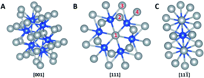
The computational calculation was performed by ab initio within the framework of the density functional theory (DFT) as implemented in Vienna Ab-initio Simulation Package (VASP). Ag32X6 polyicosahedral (plh) core–shell structures were constructed as shown in Fig. 1, in which X represents the 3d transitional metal (TM) elements (X = Sc, Ti, V, Cr, Mn, Fe, Co, Ni, Cu) in the periodic table. Ag atoms covered the X atom core to form the plh core–shell cluster. Zhang et al. showed that polyicosahedral (plh) Ag32Cu6 core–shell structure was more stable than truncated octahedral (TO) Ag32Cu6 one.29 In order to perform the DFT calculations, we identified 4 unique positions on particle surface as active sites that were marked by numbers in Fig. 1. The size of the unit cell is 20 Å × 20 Å × 20 Å with a bond length of 2.67 Å between Ag and X atoms approximately. For DFT simulations, projector augmented wave (PAW) pseudopotential was utilized to demonstrate the correlation of valence electrons.30 Generalized gradient approximation (GGA) was introduced by Perdew, Burke, and Ernzerhof (PBE) to state the electronic exchange and interactions.31 Brillouin zone sampling at the Γ point was used. An interatomic interaction in a Hartree–Fock like manner was used as the PBE+U method to correctly describe the systems with localized d and f electrons, typically transition metals.19 U parameter was chosen based on previous calculations on bi-metallic structures.32,33 A cut-off energy of 480 eV was set throughout the calculations and the self-convergence level was set to be 1 × 10⁻⁵ eV for electron relaxations. Ionic relaxation converged when the total force reached less than 0.01 eV Å−1. Entropy and zero-point energy were also considered by vibrational frequency at 300 K. Bader charge analysis was conducted to evaluate the charge transfer within the nanoparticles.34,35To carry out the calculations, two steps were conducted as lattice optimizations and electronic freedom re-optimized with no ions moved. After the Ag32X6 core–shell clusters were relaxed, we calculated the adsorption free energies of intermediates such as O, OH, O2 and OOH on the core–shell cluster to get free energies as well as overpotentials for ORR and OER. In this paper, both ORR and OER overpotentials were calculated to evaluate the bifunctionality of the structure for both reactions while the 4-electron transfer mechanism was believed to be the pathway for OER and ORR in fuel cells and metal–air batteries. The details regarding the overpotentials of OER, ORR can be found in various literatures such as Nørskov et al.,2 Man et al.,3 Zhao et al.,5,36–39 Li, et al.,4 and Zhang et al.4,40–42 Further details about the DFT calculations are provided in the ESI.†
Results and discussion
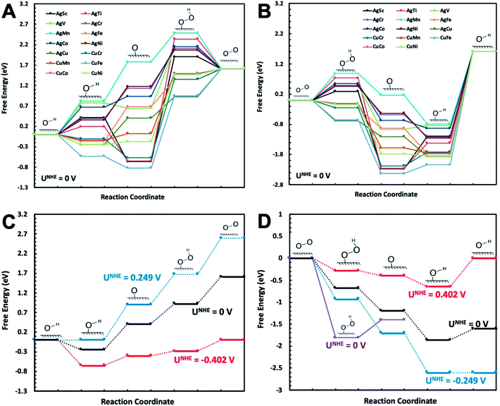
The catalytic reactions were studied on plh core–shell metal clusters as shown in Fig. 1. Four distinct active sites on the surface of the core–shell structures are labeled in Fig. 1(B). The bridge sites are not taken into consideration in this study because previous work has shown that these bridge sites are not stable for adsorptions of intermediates.29,43 There are two major types of mechanisms towards OER and ORR: 4-electron (4e) transfer mechanism with the final production of H2O, and 2-electron (2e) transfer mechanism featuring the production of H2O2. The elementary steps of these 4e and 2e transfer reactions are shown in Fig. S1 and S2,† respectively.Free energy diagrams of Ag32X6 and Cu32X6 structures for OER and ORR were plotted in Fig. 2(A) and (B), respectively. Among the core–shell structures studied in this study, Ag32Cu6 plh core–shell structure showed the best catalytic activities for OER and ORR since it has the smallest overpotential (the applied voltage that makes the reaction free energy in all elementary steps just uphill or downhill for OER and ORR, respectively). As shown in Fig. 2(C) and (D) the free energies for the Ag32Cu6 plh core–shell structure are plotted for the electrode potential of 0 V, 0.23 V and 0.402 V (equilibrium voltage for each step in OER and ORR). We also found sites 3 & 4 on the Ag32Cu6 plh core–shell structures (Fig. 1(B)) have better electrochemical activities of ORR and OER than sites 1 & 2 do. This is because sites 3 & 4 are outer-shell top sites while 1 & 2 are sort of bend inward, which may affect the adsorption of intermediates. The free energy diagram for 2-electron transfer mechanism was calculated and plotted in Fig. S3.† For comparison, the free energy of 2-electron transfer ORR mechanism of Ag32Cu6 plh core–shell structure was also plotted in Fig. 2(D). For the 2-electron transfer, the calculated electrode potential (overpotential) for Ag32Cu6 is 1.107 V, which was far larger than that for 4-electron transfer mechanism, indicating 2-electron mechanism is not favorable for plh core–shell metal structures.
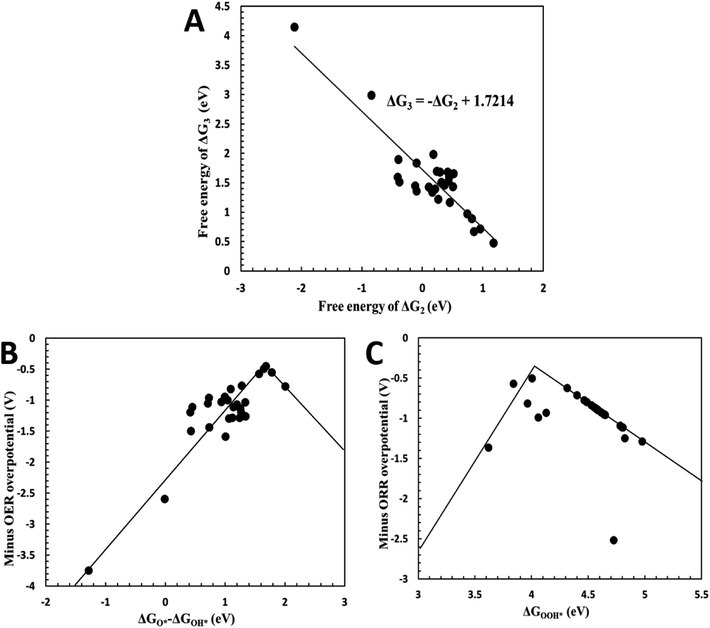
Overpotential is an indicator of catalytic activities for electrocatalysts, which is the extra energy required for a reaction than thermodynamically expected. To theoretically evaluate the electrocatalytic performance of the plh core–shell structures, the adsorption free energies of O*, OH*,  , OOH* (* refers to an active site on free surface) were calculated with the DFT method. Details regarding reaction equations, adsorption energies and overpotentials can be found in ESI.† We correlated the reaction free energy of OH* formation (ΔG3) with that of O* formation (ΔG2), as shown in Fig. 3(A). A linear regression was made with the linear least squares fitting technique and the fitting equation is ΔG3 = −ΔG2 + 1.7214. When ΔG2 equals ΔG3, the overpotential will approach its lower limit that is 0.459 V. This lower limit of the overpotential is comparable to Pt/C for ORR2 and RuO2/C for OER,3 as well as Pt-free catalysts for ORR or OER such as N-doped graphene,9,10 indicating Ag plh core–shell clusters can be used as an effective bifunctional catalyst for ORR and OER in fuel cells and metal–air batteries.
 | ||
| Fig. 3 (A) Linear fitting of reaction free energy ΔG3 and ΔG2; (B) minus OER overpotential as a function of descriptor GO* − ΔGOH*; (C) minus ORR overpotential as a function of descriptor ΔGOOH*. | ||
To establish design rules that correlate core–shell structures to their catalytic activity, the overpotentials was plotted as a function of the descriptors ΔGO* − ΔGOH* and ΔGOOH*. As shown in Fig. 3(B) and (C), OER overpotentials were drawn as a function of ΔGO* − ΔGOH* while ORR overpotentials were plotted against ΔGOOH*. Both of the plots show “volcano” relationships, on which the catalysts with the best performance are located at the summits of the volcanos. When GO* − ΔGOH* is around 1.6 eV, the OER overpotential achieves its lowest value (Fig. 3(B)), while the ORR overpotential has its lowest value at ΔGOOH* = 4 eV (Fig. 3(C)). These volcano plots enable us to predict the best electrocatalytic properties of the catalysts by considering the reaction free energies only.
Even though the descriptors ΔGO* − ΔGOH* and ΔGOOH* can relate the overpotentials to the adsorption energies of intermediates, it is more desirable for a descriptor to directly correlate the core–shell structures to the activities. To relate the overpotentials to the intrinsic properties of the materials like what Zhao et al. did in their work.37,38 We use the strain on shell atoms of plh core–shell metal structure as a descriptor for OER and ORR. The shell strain is defined as,
 | (1) |
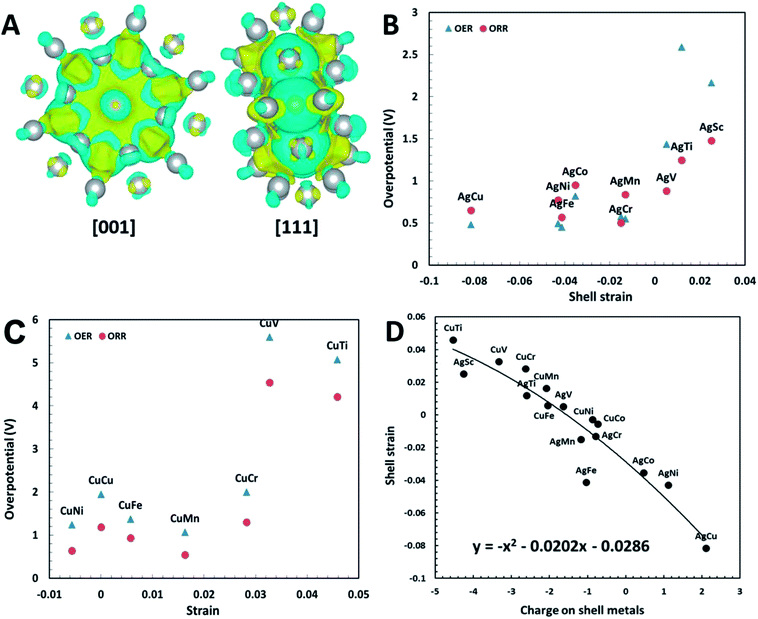
To further verify the effectiveness of the shell strain in plh core–shell clusters as the descriptor for ORR and OER, we performed another set of calculations on Cu32X6 structures. These structures are comparable to the Ag32X6 clusters with the replace of Ag by Cu. We firstly relaxed the clusters, followed by the self-convergence computations without moving of ions. The Cu core–shell structure also has a unit cell of 20 Å × 20 Å × 20 Å and the bond length between Cu and X is about 2.47 Å. Since the Cu32Sc6 plh core–shell structure is unstable because of too large difference in radius between Cu and Sc, we excluded the analysis of Cu32Sc6. The free energy diagrams of Cu32X6 structures for 2e transfer mechanisms were also plotted in Fig. S4,† respectively, and the shell strain of Cu32X6 is also determined by eqn (1). As shown in Fig. 4(C), the overpotential for Cu32X6 structures reduces with reducing the shell strain, which follows the same trend of the Ag32X6 clusters. Thus, the shell strain is a general and intrinsic descriptor that is capable of predicting the catalytic activities of the plh core–shell bifunctional catalysts for OER and ORR, and could be extended to other core–shell alloys.
The excellent catalytic activities of the core–shell structures can be attributed to the charge transfer within the core–shell structures. It was shown for doped-graphene that the charge delocalization facilitated the electrocatalytic reaction.4,40 We have carried out Bader charge transfer analysis34 for Ag32Cu6 plh core–shell structure (Fig. 4(A)). After the formation of the core–shell structure, the charge transfer occurs on the surface. With the charge redistribution, the core (Cu) carries negative charge while the shell (Ag) becomes positively charged. The positively charged shell (Ag) can easily adsorb intermediates carrying negative charges, which is the essential in ORR and OER. According to Zhang et al.'s work, the O2 dissociation energy is 0.715 eV for plh Ag32Cu6 and the density of states (DOS) at the Fermi energy level is maximal for the favorable absorption site.29 Thus, the core–shell-induced charge transfer enhances the electrocatalytic activity of plh Ag32Cu6.
Similar Bader charge transfer analysis34 was also carried out for Cu32Ni6 structure with the lowest overpotential among all Cu32X6 clusters. As shown in Fig. S5,† the Cu shell has positive charges while the Ni core carries negative charges. Similar to Ag32Cu6 clusters, the positive charges on the shell of the whole structure is believed to enhance the electrochemical activity of the core–shell cluster. However, the amount of the charges transferred in Cu32X6 is lower than that in Ag32X6, indicating Ag32X6 will show better catalytic performance than Cu32X6. This conclusion is supported by the results in Fig. 4(B) and (C), in which the overpotentials of Cu32X6 are relatively larger than those of Ag32X6.
The shell strain of the core–shell cluster is also plotted as a function of charges on shell metals (Ag or Cu) for Ag32X6 and Cu32X6 structures in Fig. 4(D). As the charge on core metals increase, the shell strain also increase with a 2nd order polynomial fitting of y = −x2 + 0.0202x − 0.0286 (round to y = −x2 + x). This demonstrates the charge transfer within the core–shell structures will influence the shell strain. Thus, one effective design strategy to enhance the electrocatalytic activities of plh core–shell metal clusters is to find the core–shell structures with the higher positive charge on shell metals.
Conclusions
Ag32X6 and Cu32X6 plh core–shell structures and their electrocatalytic properties were studied systematically with the DFT methods. The Gibbs free energy, overpotential of OER and ORR on the core–shell structures were calculated to evaluate the electrocatalytic performances. Our results show that Ag32Cu6 plh core–shell metal clusters exhibit the lowest overpotential comparable to Pt. The shell strain is found to well describe the catalytic activities of the core–shell structures. Increasing the compressive shell strain will induce more positive charge on the shell of the core–shell structures, thus enhancing the adsorption and subsequent reactions on the structures. The design principles developed from the intrinsic descriptor enables the rational design and screening of the core–shell structures for high-performance catalysts by evaluating the strain on the shell.Conflicts of interest
There are no conflicts to declare.Acknowledgements
This work is supported financially by the National Science Foundation (1561886, 1363123 and 1662288). Computational resources were provided by UNT high performance computing initiative, a project of academic computing and user services within the UNT computing and information technology center.References
- L. Carrette, K. a. Friedrich and U. Stimming, Fuel Cells, 2001, 1, 5–39 CrossRef CAS.
- J. K. Nørskov, J. Rossmeisl, A. Logadottir, L. Lindqvist, J. R. Kitchin, T. Bligaard and H. Jónsson, J. Phys. Chem. B, 2004, 108, 17886–17892 CrossRef.
- I. C. Man, H. Y. Su, F. Calle-Vallejo, H. A. Hansen, J. I. Martínez, N. G. Inoglu, J. Kitchin, T. F. Jaramillo, J. K. Nørskov and J. Rossmeisl, ChemCatChem, 2011, 3, 1159–1165 CrossRef CAS.
- M. Li, L. Zhang, Q. Xu, J. Niu and Z. Xia, J. Catal., 2014, 314, 66–72 CrossRef CAS.
- J. Zhang, Z. Zhao, Z. Xia and L. Dai, Nat. Nanotechnol., 2015, 10, 444–452 CrossRef CAS PubMed.
- S. Wang, L. Zhang, Z. Xia, A. Roy, D. W. Chang, J.-B. Baek and L. Dai, Angew. Chem., Int. Ed. Engl., 2012, 51, 4209–4212 CrossRef CAS PubMed.
- W. Zhong, W. Tu, S. Feng and A. Xu, J. Alloys Compd., 2019, 772, 669–674 CrossRef CAS.
- Z. Lin, C. Wang, Z. Wang, Q. Liu, C. Le, B. Lin and S. Chen, Electrochim. Acta, 2019, 294, 142–147 CrossRef CAS.
- S. Zhou, N. Liu, Z. Wang and J. Zhao, ACS Appl. Mater. Interfaces, 2017, 9, 22578–22587 CrossRef CAS.
- W. Pei, S. Zhou, Y. Bai and J. Zhao, Carbon, 2018, 133, 260–266 CrossRef CAS.
- X. Xie, M. Wei, L. Du, Y. Nie, X. Qi, Y. Shao and Z. Wei, J. Mater. Chem. A, 2017, 5, 15390–15394 RSC.
- Y. Zhou, Q. Lu, Z. Zhuang, G. S. Hutchings, S. Kattel, Y. Yan, J. G. Chen, J. Q. Xiao and F. Jiao, Adv. Energy Mater., 2015, 5, 1–4 Search PubMed.
- N. Zhang, F. Chen, D. Liu and Z. Xia, ACS Appl. Energy Mater., 2018, 1, 4385–4394 CrossRef CAS.
- N. Zhang, F. Chen, X. Wu, Q. Wang, A. Qaseem and Z. Xia, J. Mater. Chem. A, 2017, 5, 7043–7054 RSC.
- J. Greeley, I. E. L. Stephens, A. S. Bondarenko, T. P. Johansson, H. A. Hansen, T. F. Jaramillo, J. Rossmeisl, I. Chorkendorff and J. K. Nørskov, Nat. Chem., 2009, 1, 552–556 CrossRef CAS.
- J. X. Wang, H. Inada, L. Wu, Y. Zhu, Y. Choi, P. Liu, W.-P. Zhou and R. R. Adzic, J. Am. Chem. Soc., 2009, 131, 17298–17302 CrossRef CAS PubMed.
- D. Wang, H. L. Xin, R. Hovden, H. Wang, Y. Yu, D. A. Muller, F. J. DiSalvo and H. D. Abruña, Nat. Mater., 2012, 12, 81–87 CrossRef PubMed.
- L. Gan, M. Heggen, S. Rudi and P. Strasser, Nano Lett., 2012, 12, 5423–5430 CrossRef CAS PubMed.
- A. Qaseem, F. Chen, X. Wu and R. L. Johnston, Catal. Sci. Technol., 2016, 6, 3317–3340 RSC.
- T. Fu, J. Fang, C. Wang and J. Zhao, J. Mater. Chem. A, 2016, 4, 8803–8811 RSC.
- J. A. Bordley and M. A. El-Sayed, J. Phys. Chem. C, 2016, 120, 14643–14651 CrossRef CAS.
- Y. Chi, L. Zhao, X. Lu, C. An, W. Guo and C. M. L. Wu, J. Mater. Sci., 2016, 51, 1–15 CrossRef.
- J. Cao, M. Guo, J. Wu, J. Xu, W. Wang and Z. Chen, J. Power Sources, 2015, 277, 155–160 CrossRef CAS.
- M. Chatenet, M. Aurousseau, R. Durand and F. Andolfatto, J. Electrochem. Soc., 2003, 150, D47 CrossRef CAS.
- K. Shin, D. H. Kim and H. M. Lee, ChemSusChem, 2013, 6, 1044–1049 CrossRef CAS PubMed.
- P. Strasser, S. Koh, T. Anniyev, J. Greeley, K. More, C. Yu, Z. Liu, S. Kaya, D. Nordlund, H. Ogasawara, M. F. Toney and A. Nilsson, Nat. Chem., 2010, 2, 454–460 CrossRef CAS PubMed.
- K. Shin, D. H. Kim, S. C. Yeo and H. M. Lee, Catal. Today, 2012, 185, 94–98 CrossRef CAS.
- H. Jiang, T. Akita, T. Ishida, M. Haruta and Q. Xu, J. Am. Chem. Soc., 2011, 133, 1304–1306 CrossRef CAS.
- N. Zhang, F. Y. Chen and X. Q. Wu, Sci. Rep., 2015, 5, 1–12 Search PubMed.
- P. E. Blöchl, Phys. Rev. B: Condens. Matter Mater. Phys., 1994, 50, 17953–17979 CrossRef.
- J. P. Perdew, K. Burke and M. Ernzerhof, D. of Physics and N. O. L. 70118, J. Quantum Theory Group Tulane University, Phys. Rev. Lett., 1996, 77, 3865–3868 CrossRef CAS PubMed.
- A. I. Liechtenstein, V. I. Anisimov and J. Zaanen, Phys. Rev. B: Condens. Matter Mater. Phys., 1995, 52, 5467–5470 CrossRef.
- H. Dederichs, Phys. Rev. B: Condens. Matter Mater. Phys., 1994, 50, 16861 CrossRef.
- W. Tang, E. Sanville and G. Henkelman, J. Phys.: Condens. Matter, 2009, 21, 084204 CrossRef CAS.
- G. Henkelman, A. Arnaldsson and H. Jónsson, Comput. Mater. Sci., 2006, 36, 354–360 CrossRef.
- Z. Zhao, L. Zhang and Z. Xia, J. Phys. Chem. C, 2016, 120, 2166–2175 CrossRef CAS.
- Z. Zhao and Z. Xia, ACS Catal., 2016, 1553–1558 CrossRef CAS.
- Z. Zhao, M. Li, L. Zhang, L. Dai and Z. Xia, Adv. Mater., 2015, 27, 6834–6840 CrossRef CAS PubMed.
- Z. Zhao and Z. Xia, MRS Adv., 2016, 1–5 Search PubMed.
- L. Zhang and Z. Xia, J. Phys. Chem. C, 2011, 115, 11170–11176 CrossRef CAS.
- L. Zhang, J. Niu, M. Li and Z. Xia, J. Phys. Chem. C, 2014, 118, 3545–3553 CrossRef CAS.
- L. Zhang, J. Niu, L. Dai and Z. Xia, Langmuir, 2012, 28, 7542–7550 CrossRef CAS PubMed.
- X. Wu, F. Chen, Y. Jin, N. Zhang and R. L. Johnston, ACS Appl. Mater. Interfaces, 2015, 7, 17782–17791 CrossRef CAS PubMed.
Footnote |
| † Electronic supplementary information (ESI) available. See DOI: 10.1039/c8ra09122f |
| This journal is © The Royal Society of Chemistry 2019 |


![[1 with combining macron]](https://www.rsc.org/images/entities/char_0031_0304.gif) ] view. Four distinct active sites are marked in (B). Color legend: grey = shell elements, blue = core elements.
] view. Four distinct active sites are marked in (B). Color legend: grey = shell elements, blue = core elements.
