
 Open Access Article
 This Open Access Article is licensed under a Creative Commons Attribution-Non Commercial 3.0 Unported Licence
Well-dispersed nickel nanoparticles on the external and internal surfaces of SBA-15 for hydrocracking of pyrolyzed α-cellulose†
Wega Trisunaryanti*,
Endah Suarsih ,
Triyono and
Iip Izul Falah
,
Triyono and
Iip Izul Falah
Department of Chemistry, Universitas Gadjah Mada, Indonesia. E-mail: wegats@ugm.ac.id
First published on 9th January 2019
Abstract
Catalysts comprising nickel supported on SBA-15 were prepared by wet impregnation and co-impregnation methods. Wet impregnation was performed by directly dispersing an Ni(NO3)2·6H2O aqueous solution into SBA-15, whereas in co-impregnation, ethylene glycol (EG) was added to nickel nitrate aqueous solution prior to dispersion into SBA-15. After drying and calcination, NiO/SBA-15w and NiO/SBA-15c were produced. Later, after the reduction process, Ni/SBA-15w and Ni/SBA-15c were obtained. The prepared catalysts were evaluated for the hydrocracking of pyrolyzed α-cellulose. The TEM images revealed that the catalysts prepared by wet impregnation showed inhomogeneous distribution of nickel loading, whereas catalysts prepared by co-impregnation using EG exhibited homogeneous distribution and formed no nickel aggregates. During hydrocracking of pyrolyzed α-cellulose, Ni/SBA-15c with total acidity, nickel loading, particle size, and specific surface area of 7.27 m mol g−1, 5.20 wt%, 3.17 nm, and 310.0 m2 g−1, respectively, exhibited the best catalytic performance compared to other prepared catalysts with 67.35 wt% conversion of liquid product with maximum selectivity in producing 13.09 wt% of 3-methyl-pentane. Moreover, Ni/SBA-15w with total acidity, nickel loading, particle size, and specific surface area of 10.87 m mol g−1, 8.15 wt%, 7.01 nm, and 628.0 m2 g−1, respectively, produced 69.89 wt% liquid product without hydrocarbons. Study of selectivity towards the formation of liquid hydrocarbons was carried out via double step hydrocracking using Ni/SBA-15w, and 18.55 wt% of n-hexane was produced in the liquid product.
1. Introduction
Green energy production will continue indefinitely with a constant supply of biomass waste. The valorization of biomass waste has gained much interest because it has become one of the most promising renewable solutions for the substitution of fossil resources not only in energy applications but also for the production of many chemicals and biomaterials.1 One of the many advantages of biomass-based-fuels is that they reduce emissions of gases such as CO2, SO2, and NOx and contribute to global economic sustainability.2–5 Biomass provides a promising stock for producing renewable fuels and chemicals, especially for liquid fuels.6,7 However, due to the complexity of biomass conversion, products are typically obtained with very low yield and purity. Therefore, upgrading treatments are required to obtain an excellent conversion process.Cellulosic conversion into fuels is challenging and requires effective catalytic systems. The search for catalysts with excellent catalytic activity, selectivity, and resistance to coke formation and sintering is an ongoing process. It has been reported that the types of metal and support play an important role in increasing the efficiency of the conversion process.8 Mesoporous catalysts can improve the development of new biofuel generation processes because of their important properties such as high concentration of active sites, high thermal/hydrothermal stability and enhanced shape selectivity.9 One of the most widely used mesoporous supports is SBA-15 and it has a high specific surface area, excellent thermal stability, tunable porosity, and uniform hexagonal pores and thick pore walls.10 Among the mesoporous materials, SBA-15 with these advantages has attracted much more attention for applications as catalysts as well as catalyst supports.11,12
Supported nickel catalysts have attracted significant attention for their extensive applications in various industrial processes.13 During biomass conversion, nickel-based catalysts upgrade the composition of the liquid phase.8 However, nickel-based catalysts are more easily deactivated because of carbon deposition and active metal species sintering; during harsh reactions, the tendency of carbon deposition hinders stable catalytic performance.14 Designing catalysts with strong metal-support interactions and well confinement of metal particles is one possible solution for this drawback.10 Small nickel nanoparticles with strong metal-support interactions reportedly have limited mobility on the surface and resistance to sintering.10,15 A simple wet impregnation process is generally used as a preparation method. However, this method reportedly causes poor dispersions due to agglomeration during drying and calcination.16 To obtain highly active and dispersed nickel catalysts by the impregnation method, several approaches and techniques have been developed such as using an organic nickel precursor and surface modification.17,18
Formerly, it was reported that the polyol-assisted route (co-impregnation) of Ni/SBA-15 catalyst with high dispersion of small nickel particles results in more active sites for the reaction, leading to higher catalytic activity.19 In addition, small nickel particles with strong metal-support interactions prepared via co-impregnation significantly enhanced the dispersion, resulting in high activity and excellent coke resistance.20,21 A nickel catalyst supported on SBA-15 via co-impregnation using ethylene glycol was also reportedly synthesized and it showed excellent stability in the dry reforming of methane with CO2 to produce syngas and hydrogen.22 Ni/SBA-15 also showed high activity and achieved high hydrocarbon yields in the hydrodeoxygenation reaction for upgrading lignin-derived bio-oils.23
Based on these considerations, nickel catalysts supported on SBA-15 were synthesized via wet impregnation and co-impregnation using ethylene glycol. The catalytic performance of nickel catalysts in reduced and oxide forms was evaluated for the hydrocracking of pyrolyzed α-cellulose as a model of biomass. The selectivity of catalysts toward the formation of liquid hydrocarbons was studied through double step hydrocracking.
2. Experimental
2.1 Catalyst preparation
SBA-15 as a support material was supplied by Green Stone Swiss Co. Ltd. and Ni(NO3)2·6H2O as a salt precursor was supplied by Merck. Nickel supported on SBA-15 catalysts were set as 10.0 wt% and were prepared by the wet and co-impregnation methods.20 The only difference between the wet and co-impregnation methods was the addition of a defined amount of ethylene glycol (Ni/EG ratio = 1) during the dissolution of the salt precursor. The mixtures were stirred and impregnated in the SBA-15 support, followed by standing overnight; they were evaporated and dried at 100 °C. Afterwards, the dried solids were calcined at 500 °C for 5 hours in the air. At this stage, the solids were denoted as NiO/SBA-15c and NiO/SBA-15w. A further step was the reduction process, where the solids were streamed by 20 ml min−1 H2 gas at 400 °C for 3 hours to prepare zero valences of nickel (denoted as Ni/SBA-15c and Ni/SBA-15w).2.2 Catalyst test
The hydrocracking of pyrolyzed α-cellulose was carried out by using a set of cracking reactor. A semi-batch reactor system using stainless steel tube with an inner diameter of 2.80 cm, outer diameter of 3.10 cm, and length of 21.00 cm was used. Prior to the hydrocracking process, α-cellulose was pyrolyzed using the same reactor at 600 °C for 3 hours and streamed by N2 gas with 20 ml min−1 flow rate. In the hydrocracking of pyrolyzed α-cellulose, the catalyst and pyrolyzed α-cellulose with the ratio of 1![[thin space (1/6-em)]](https://www.rsc.org/images/entities/char_2009.gif) :30 were placed into the semi-batch reactor. The reactor containing the catalyst and pyrolyzed α-cellulose was streamed by H2 gas with 20 ml min−1 flow rate and heated at 450 °C for 2 hours. The heart-shaped flask was used to place the liquid product. The liquid product was characterized by using Gas Chromatography-Mass Spectroscopy (Shimadzu QP2010S).
:30 were placed into the semi-batch reactor. The reactor containing the catalyst and pyrolyzed α-cellulose was streamed by H2 gas with 20 ml min−1 flow rate and heated at 450 °C for 2 hours. The heart-shaped flask was used to place the liquid product. The liquid product was characterized by using Gas Chromatography-Mass Spectroscopy (Shimadzu QP2010S).
2.3 Catalyst characterization
The acidity of the catalysts was tested by the gravimetric method using NH3 gas as a basic adsorbate. The amount of nickel present in the catalyst was determined by using an atomic absorption spectrophotometer (Perkin Elmer PinAAcle 900 T). The amorphous structure of SBA-15 was analyzed by an X-ray Diffractometer (Rigaku Miniflex 600) using Cu Kα radiation (0.154060 Å). The measurement conditions were in the range of 2θ = 20–80°. The particle sizes of Ni and NiO can be calculated by using the Scherrer equation. The morphology of catalyst surface was characterized by using Scanning Electron Microscope-Energy Dispersive Spectroscopy (JEOL JED 2300) with an electron beam of 15.0 kV. TEM images were determined by a JEOL-JEM-1400 microscope with an electron beam of 120 kV. The pore characteristics (Brunauer–Emmett–Teller) of the catalysts were tested by using a gas adsorption analyzer (Quantachrome NovaWin version 11.0). The pore analysis was conducted using N2 gas at 77.3 K.3. Results and discussion
3.1 Catalyst characterization
During impregnation, nickel salt solution was assumed to be adsorbed easily by mesoporous SBA-15 due to capillary pressure.24 In fact, the SBA-15 support is not completely hydrophilic, which can cause incomplete wetting and inhomogeneous nickel dispersion on pores during impregnation.25 The addition of ethylene glycol into the nickel nitrate aqueous solution has been reported to decrease the surface tension of impregnation solutions because it can act as a surfactant, which is preferred for better wetting of the support and increasing the rate of diffusion and infusion into deeper mesoporous channels of the catalyst support.22 During the drying process, the solvent was gradually removed. At this stage, the concentrated solvent with lower surface tension could diffuse deeply at first and was transported toward the internal surface of the mesoporous channels via capillary forces.22 At the end of drying, the catalyst exhibited strong interaction with the internal surface of the support and inhibited the redistribution of the impregnation solution; also, uniform distribution of the active component in the mesopore channels could be achieved. In contrast, the precursor exhibited weak interaction with the support without EG; the concentrated solvent adsorbed by the mesoporous pores could be back diffused by higher surface tension and it migrated toward the external surface of the mesoporous channels, resulting in a concentration build up on the external rim of the support. As a consequence, inhomogeneous distributions of the precursor were observed.22The loading of Ni on SBA-15 affected the acidity of the catalyst. As presented in Table 1, the presence of nickel increased the acidity of the catalysts and as the concentration of nickel increased, the acidity increased. This was due to the Lewis acid (electron acceptor) sites provided by nickel. Comparing the oxide form and zero valences of the catalysts, it was shown that the reduced form of nickel (Ni) supported on SBA-15 exhibited higher acidity than the oxide form of nickel (NiO). This was because the reduced form of nickel has more orbitals to accept electrons, whereas the oxide form of nickel has less orbitals because of the presence of oxygen.
| Samples | Nickel loadinga (wt%) | Acidityb (m mol g−1) | SBETc (m2 g−1) | Pore volumec (cm3 g−1) | Average pore diameterc (nm) | Ni species particle sized (nm) |
|---|---|---|---|---|---|---|
| a Nickel loadings were determined by an atomic absorption spectrophotometer.b Acidity of the catalysts was determined gravimetrically using NH3 gas as a basic adsorbate.c SBET and pore volumes and diameters of the catalysts were calculated using BET and BJH theory, respectively.d Particle size was calculated using Scherrer's equation. | ||||||
| SBA-15 | — | 3.99 | 623.80 | 1.05 | 6.75 | — |
| NiO/SBA-15w | 5.07 | 4.85 | 419.80 | 0.80 | 7.66 | 9.05 |
| NiO/SBA-15c | 5.25 | 5.06 | 422.20 | 0.86 | 8.19 | 2.91 |
| Ni/SBA-15w | 8.15 | 10.87 | 628.00 | 0.88 | 5.60 | 7.01 |
| Ni/SBA-15c | 5.20 | 7.27 | 310.00 | 0.64 | 8.24 | 3.17 |
The physical properties of the catalysts, as presented in Table 1, show that the loading of nickel on SBA-15 decreases the pore volume due to shrinkage of silica walls by the heat treatment or partial blockage of mesoporous channels by nickel nanoparticles. The impregnation of nickel on SBA-15 also decreased the specific surface area of the catalysts except for Ni/SBA-15w. This may have been caused by the splitting of pores by the aggregates of impregnated Ni during the impregnation process. The average pore diameter may also confirm the splitting of pores in the Ni/SBA-15w catalyst since it has the lowest pore diameter. As seen in Table 1, Ni/SBA-15w has the highest loading of nickel, which might be affected by the impregnation process; thus, the splitting of pores cannot be avoided. As a consequence, it can increase the specific surface area due to the decrease in average pore diameter.
The high-angle XRD patterns of the catalysts are shown in Fig. 1. In all high-angle diffractograms, it is shown that the characteristic peak of SBA-15 corresponded to 2θ of approximately 20–30°, resulting in a broad peak. After impregnation of nickel into SBA-15, it was clearly shown that the characteristic peaks of SBA-15 are relatively similar. This result indicates that after the impregnation of nickel into SBA-15, the structure of SBA-15 was not damaged.
 | ||
| Fig. 1 Wide angle XRD patterns of catalysts (a) SBA-15, (b) Ni/SBA-15w, (c) Ni/SBA-15c, (d) NiO/SBA-15w, and (e) NiO/SBA-15c. | ||
The impregnation of nickel into SBA-15 apparently results in peaks that correspond to the presence of NiO and Ni in the catalysts. Catalysts prepared via the wet impregnation method showed three strong and sharp diffraction peaks at 2θ of around 37°, 43° and 63°, indicating that nickel species were present in the form of cubic NiO (JCPDS no. 01-1239); the peak at 2θ of around 42.7° indicated that nickel species were present in the form of cubic Ni (JCPDS no. 02-0850). Furthermore, catalysts prepared via co-impregnation showed weak and diffuse diffraction peaks of NiO and Ni. This confirmed that NiO and Ni particles were very small and highly dispersed on the SBA-15 support. The average particle size of NiO was evaluated by the Scherrer equation. The average particle sizes for NiO/SBA-15w, NiO/SBA-15c, Ni/SBA-15w, and Ni/SBA-15c were 9.05 nm, 2.91 nm, 7.01 nm, and 3.17 nm, respectively. By this evaluation, it was confirmed that NiO particles prepared via co-impregnation have smaller particle sizes and possibly superior catalytic performance. In addition, the characteristic peaks of NiO that were also observed for the reduced form of catalysts (Ni/SBA-15w and Ni/SBA-15c) were caused by the incomplete reduction process.
Brunauer–Emmet–Teller (BET) theory explains the physical adsorption of gas molecules on a solid surface. It applies to the system of multilayer adsorption and usually utilizes probing gases that do not chemically react with material surfaces as adsorbates to quantify the specific surface area. Nitrogen is the most commonly employed gaseous adsorbate used for surface probing by BET methods. For this reason, the standard BET analysis is mostly conducted at the boiling temperature of N2 (77 K). As presented in Fig. 2, the nitrogen adsorption/desorption isotherms are typical of a reversible type IV isotherm with a hysteresis loop based on IUPAC classification scheme for mesoporous materials with narrow pore size distribution of the cylindrical pores.
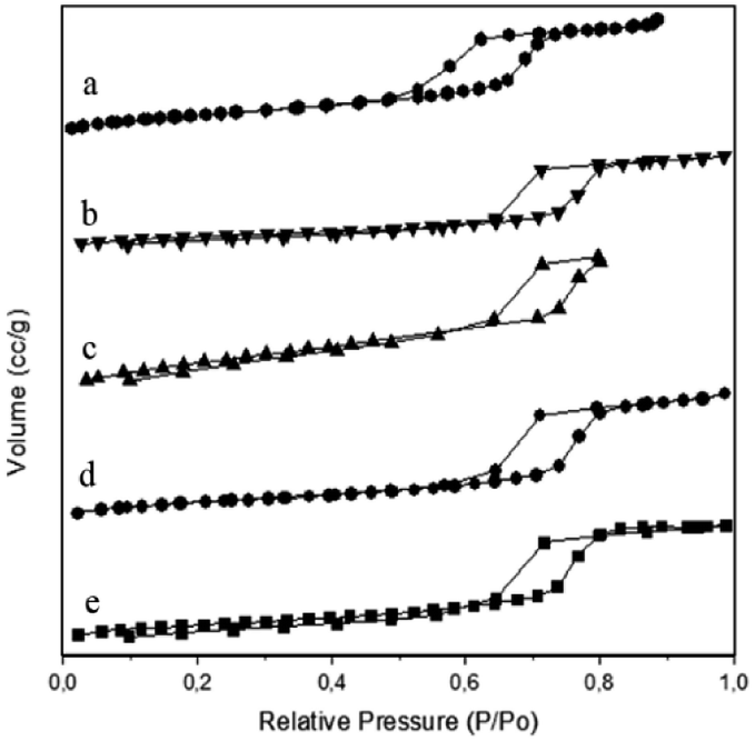 | ||
| Fig. 2 Nitrogen adsorption/desorption isotherms of N2 gas of (a) SBA-15, (b) Ni/SBA-15c, (c) Ni/SBA-15w, (d) NiO/SBA-15c, (e) NiO/SBA-15w catalysts. | ||
The pore size distributions are presented in Fig. 3, and they were analyzed by using BJH desorption data. By processing the data, we inferred that the best pore distribution was observed for SBA-15, which was indicated by the narrowest peak formed due to its homogeneous pore size. After the impregnation process, there were several changes in terms of pore distribution. As seen in Fig. 3, the pore distribution of catalysts after impregnation of nickel shifted to the right, indicating that pore diameters have changed. These changes might be caused by the shrinkage of SBA-15 wall due to the heating treatment or the formation of new pores as an effect of the impregnation process. Therefore, the diameter changes of the pores will vary the diameter size and the pores will become more heterogeneous.
 | ||
| Fig. 3 Pore distributions of catalysts. | ||
The SEM images of the catalysts are shown in Fig. 4. These images reveal that the SBA-15 morphology consisted of short rod-like aggregates. After impregnation, it can be seen in Fig. 4 that the SEM image looks brighter. This was due to the presence of nickel. In SEM, when an electron is ejected to the specimen that consists of a metal, the secondary electron will be captured, making the image look brighter due to the physical properties of the metal. Comparing the SEM images of the nickel catalysts prepared by wet impregnation and co-impregnation (Fig. 4), it was clearly shown that there were more nickel agglomerations during wet impregnation on the external surface of SBA-15, as indicated by the rough surface. The Ni/SBA-15 catalyst with most loaded nickel tended to form aggregates rapidly during calcination and reduction processes, leading to the formation of severe agglomeration (Fig. 4D).
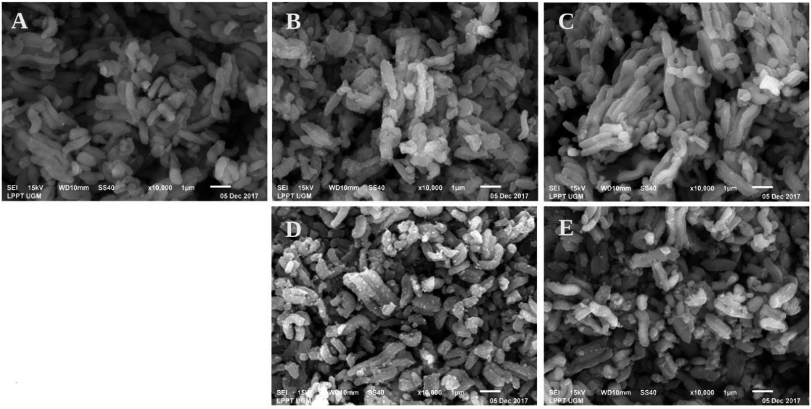 | ||
| Fig. 4 SEM images of (A) SBA-15, (B) NiO/SBA-15w, (C) NiO/SBA-15c, (D) Ni/SBA-15w, and (E) Ni/SBA-15c catalysts. | ||
Catalysts prepared by co-impregnation using ethylene glycol showed fewer nickel aggregates, as confirmed by Fig. 4C and E. These SEM images confirm that the addition of ethylene glycol may resist the formation of aggregates in the catalyst, which can be a drawback. These SEM images correspond to Scherrer's evaluation of the average size of nickel particles present in the catalysts based on X-ray diffraction data. The aggregates from nickel loading caused increase in peak intensities due to large nickel particles.
Nickel particles with smaller sizes and stronger metal-support interactions are favored due to their better resistance on sintering and coke formation. Nanoparticles with high surface areas tend to minimize the aggregation energy. Large nickel particles may be obtained from the sintering of nickel nanoparticles that have loose contact with the support due to weak metal-support interaction.
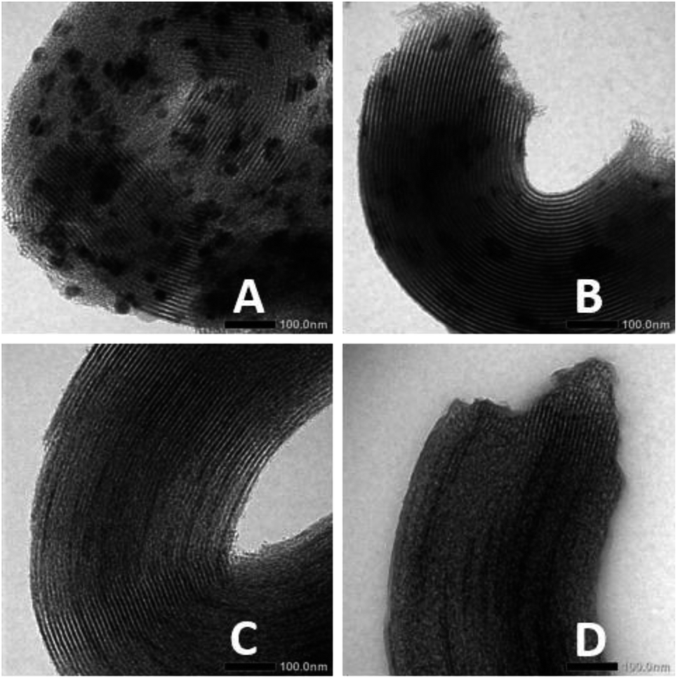
The above results are confirmed by TEM images of the catalysts, as shown in Fig. 5. The typical structure of SBA-15 observed was an ordered mesoporous structure. The TEM images of catalysts prepared via wet and co-impregnation show a very clear distinction. For the catalysts prepared via wet impregnation, NiO is usually present in a form of bulk oxide and is difficult to deliver to the channels, which may cause aggregation on the external surface of the support.10 Fig. 5B and D show the large aggregates of nickel particles on the external surface of SBA-15 due to their inability to enter the channels. In this case, small nickel particles only filled a small part of the channels because of the inhomogeneous distributions of nickel particles that were formed due to inability of water as a solvent to suppress the redistribution and agglomeration during drying, calcination, and reduction processes; this result corresponded to previous results.22 Meanwhile, on catalysts prepared via co-impregnation, as seen in Fig. 5C and E, nickel particles were anchored inside the channels of SBA-15 due to the presence of EG, which could confine the small nickel nanoparticles in place. This confinement effect resulted in the homogeneous and well dispersion suppressing the growth of metal particles, which could improve resistance to coking and sintering.
 | ||
| Fig. 5 TEM images of (A) SBA-15, (B) NiO/SBA-15w, (C) NiO/SBA-15c, (D) Ni/SBA-15w, (E) Ni/SBA-15c catalysts. | ||
3.2 Catalytic activity in the hydrocracking of pyrolyzed α-cellulose
In the investigation of catalytic activity, the prepared catalysts were used in the hydrocracking of pyrolyzed α-cellulose. Prior to the hydrocracking process, α-cellulose should be pyrolyzed to obtain the liquid form of α-cellulose. Pyrolysis was carried out by heating α-cellulose at 600 °C while being streamed by N2 gas (20 cm3 min−1). The pyrolysis products included a carbon-rich solid called char, an incondensable gas fraction and a condensable vapor fraction composed of H2O and a complex mixture of organic compounds (Table 2).| Content (wt%) | Name | Mol. formula |
|---|---|---|
| a Yield of pyrolyzed α-cellulose (liquid) is 45.42 wt%. | ||
| 7.20 | Formic acid | CH2O2 |
| 9.44 | 2,3-Butanedione | C4H6O2 |
| 6.82 | Acetic acid | C2H4O2 |
| 10.27 | 1-Hydroxy-2-propanone | C3H6O2 |
| 2.51 | Oxirane (butoxymethyl) | C7H14O2 |
| 2.78 | 1-Hydroxy-2-butanone | C4H8O2 |
| 4.49 | 2-Furancarboxaldehyde | C5H4O2 |
| 2.12 | 2-Furanmethanol | C5H6O2 |
As expected, the result of the pyrolysis process was the conversion of α-cellulose into oxygenated compounds. The resulting compounds were analyzed by using gas chromatography-mass spectrometry; they predominantly contained carboxylic acid compounds (formic acid; acetic acid), ketones (2,3-butanedione; 1-hydroxy-2-propanone; 1-hydroxy-2-butanone), and furan compounds (2-furancarboxaldehyde; 2-furanmethanol). This result corresponds to that of a former investigation.26 The mixture of these compounds was called as bio-oil. Bio-oils are generally presented as dark brown organic liquids, which have a special smoky odor. The obtained bio-oil was a yellow clear liquid with a very strong odor. With time, this yellow clear liquid turned dark brown and the presence of particles could be observed. This occurred because of the polymerization process during the aging of oil and also due to the oxidation process, which might occur because of the contact with oxygen. Based on these results, we inferred that bio-oil was composed of unstable compounds.
The upgrading of bio-oil was conducted by the hydrocracking process using the prepared catalysts. In the catalytic hydrocracking of bio-oil from pyrolyzed α-cellulose, we obtained a more stable liquid, which was called as biofuel. This hydrocracking process is considered to be the bio-refinery of biomass; in this case, α-cellulose was converted into bio-oil by pyrolysis and finally into biofuel by the hydrocracking process. The hydrocracking process was performed by a hydrogenation reaction at 450 °C in the presence of H2 (20 cm3 min−1) in a hydrocracking reactor. This hydrogenation process can simultaneously be called as hydrodeoxygenation because at this stage, hydrogenation as well as deoxygenation reactions can occur. The term hydrocracking was used because during the heating process, the components of bio-oil tend to be polymerized, which was then cracked by H2 gas to obtain the desired product. This catalytic activity test at this stage was done by using the prepared catalysts. The percentages of product distribution in the hydrocracking process are shown in Table 3.
| Catalyst | Nickel loading (wt%) | Hydrocracking product | Liquid fraction per Ni loading | ||
|---|---|---|---|---|---|
| Liquid fraction (wt%) | Gas fraction (wt%) | Coke (wt%) | |||
| Thermal | — | 48.61 | 51.39 | 0.00 | — |
| SBA-15 | — | 85.96 | 13.16 | 0.88 | — |
| NiO/SBA-15w | 5.07 | 66.13 | 31.26 | 2.61 | 13.04 |
| NiO/SBA-15c | 5.25 | 60.28 | 38.86 | 0.86 | 11.48 |
| Ni/SBA-15w | 8.15 | 69.89 | 28.82 | 1.29 | 8.58 |
| Ni/SBA-15c | 5.20 | 67.35 | 31.83 | 0.82 | 12.95 |
The investigation of the catalyst performance on hydrocracking of pyrolyzed α-cellulose is shown in Table 3. The results showed that the hydrocracking process resulted in three phases of the product, which were a liquid fraction, gas fraction, and coke. As expected, the hydrocracking process with a poor conversion value of the liquid product was thermal hydrocracking without a catalyst. The catalytic cracking over catalysts resulted in more liquid products, and the thermal cracking resulted in more gas products. This result could be caused by the differences in the reaction mechanisms.27,28 In thermal cracking, the reaction occurs through the formation of radical ions triggered by a high temperature without a catalyst to produce short carbon chains, whereas in catalytic hydrocracking, the reaction takes place via the formation of carbocations to produce longer carbon chains.
The highest conversion value of the liquid product was obtained by hydrocracking using Ni/SBA-15w as a catalyst. This was due to the highest loading of nickel present in the catalyst. By looking at the percentage of liquid product obtained and the nickel content in the catalyst comparatively, it was inferred that Ni/SBA-15w gives the highest yield of the liquid product compared to the other prepared catalysts with the nickel content of 8.15%. Ni/SBA-15c obtained by co-impregnation gave 67.35% yield of liquid product with only 5.20% of nickel present in the catalyst. These results show that Ni/SBA-15 prepared by co-impregnation can be compared to the one prepared by wet impregnation in terms of liquid product yields with less amount of nickel present in the catalyst. However, in the view of liquid fraction per Ni loading also presented in Table 3, NiO/SBA-15w exhibited the maximum value of 13.04 with no selectivity towards the formation of hydrocarbons. The value of liquid fraction per Ni loading was obtained from the division of the yield of the liquid fraction by Ni loading.
The production of coke after hydrocracking process is shown in Table 3. Based on the table, it is shown that the formation of coke in NiO and Ni impregnated into SBA-15 via co-impregnation was very much lower compared to that observed for the catalysts prepared via wet impregnation; also, it was even smaller compared to that observed for SBA-15. This fact supports the previous observation reported by many researchers: co-impregnation by using ethylene glycol can reduce the formation of coke, which can affect catalyst deactivation.
When the reaction occurs and coke is formed, it might cause decrease in catalytic activity due to deactivation of the catalyst active sites. Comparing the TEM images of Ni/SBA-15w and Ni/SBA-15c (Fig. 6) before and after hydrocracking of pyrolyzed α-cellulose, it is confirmed that the Ni/SBA-15c catalyst (Fig. 6C and D) has excellent stability towards hydrocracking of pyrolyzed α-cellulose as there is only slight blocking of the pores of the catalyst due to slight formation of coke. On the other hand, the TEM image of Ni/SBA-15w (Fig. 6A and B) after hydrocracking of pyrolyzed α-cellulose is quite darker, indicating that the formation of coke in the reaction was substantial and may cause catalyst deactivation.
 | ||
| Fig. 6 TEM images of Ni/SBA-15w (A) before and (B) after hydrocracking of pyrolyzed α-cellulose and those of Ni/SBA-15c (C) before and (D) after hydrocracking of pyrolyzed α-cellulose. | ||
The selectivity of liquid product to the hydrocarbon formation is shown in Table 4. In Table 4, the resulting compounds are grouped into carboxylic acid, hydroxyl ketone, furan compound, and hydrocarbons (alkene; alkane). Based on the table showing four major products resulting from hydrocracking, it is found that thermal hydrocracking produced a long carboxylic acid. During thermal hydrocracking, a hydrocarbon (dodecane) was also obtained but only in a small amount of 4.21 wt%. For the SBA-15 catalyst without impregnation by nickel, it was found that the catalyst was not selective to furan compound. All other catalysts impregnated by nickel were selective to the production of carboxylic acid, hydroxyl ketone, furan, and hydrocarbons.
| Compound | Product percentage (wt%) | ||||||
|---|---|---|---|---|---|---|---|
| Thermal | SBA-15 | NiO/SBA-15w | NiO/SBA-15c | Ni/SBA-15w | Ni/SBA-15c | ||
| 1 step | 2 step | ||||||
| Dodecanoic acid | 11.84 | ||||||
| Decanoic acid | 2.92 | ||||||
| Tetradecanoic acid | 3.15 | ||||||
| Acetic acid | 18.92 | 17.12 | 4.59 | 15.45 | 22.51 | 12.11 | |
| Propanoic acid | 12.30 | 11.01 | 7.21 | ||||
| Ethanedioic | 12.31 | ||||||
| 1-Hydroxy-2-propanone | 17.48 | 11.66 | 7.70 | 17.99 | |||
| 1-Hydroxy-2-butanone | 9.86 | ||||||
| 2-Furancarboxaldehyde | 11.12 | 9.27 | 8.17 | 14.57 | 13.43 | ||
| 1-Methyl-4(pent-1-en-4-on-2-yl) cyclohexane | 9.84 | ||||||
| n-Hexane | 18.55 | ||||||
| 3-Methyl-pentane | 10.58 | 13.09 | |||||
| Dodecane | 4.21 | ||||||
Comparing the selectivities of nickel catalyst impregnated into SBA-15 in the production of biofuel, we observed that the catalysts prepared by co-impregnation, i.e., both forms of NiO and Ni impregnated on SBA-15 showed selectivity toward the formation of hydrocarbons due to the formation of a branched alkane (3-methyl-pentane). On the other hand, the prepared catalysts via wet impregnation showed negligible selectivity towards hydrocarbon formation. This was because no hydrocarbons were obtained in the one step of hydrocracking. The investigation of two-step hydrotreatment of bio-oils with very contrasting compositions has been reported to give low oxygen contents in the product.29 The selectivity towards hydrocarbon was shown after the second hydrocracking was conducted using Ni/SBA-15w and n-hexane was produced. When the resulting hydrocarbons were compared, 3-methyl-pentane obtained from the hydrocracking process using catalysts via impregnation was more preferable because it has a higher octane number compared to n-hexane.
4. Conclusions
In this study, the preparation of catalysts via the co-impregnation method was successfully applied for NiO/SBA-15c and Ni/SBA-15c catalysts, which showed excellent activity and resistance towards coke formation in the hydrocracking of pyrolyzed α-cellulose. The TEM images reveal that catalysts prepared by wet impregnation show inhomogeneous distribution of nickel loading, whereas catalysts prepared by co-impregnation using EG exhibit homogeneous distribution and form no nickel aggregates. During hydrocracking of pyrolyzed α-cellulose, Ni/SBA-15c with total acidity, nickel loading, particle size, and specific surface area of 7.27 m mol g−1, 5.20 wt%, 3.17 nm, and 310.0 m2 g−1, respectively, exhibited best catalytic performance among other prepared catalysts with 67.35 wt% conversion of liquid product with maximum selectivity in producing 13.09 wt% of 3-methyl-pentane. Moreover, Ni/SBA-15w with total acidity, nickel loading, particle size, and specific surface area of 10.87 m mol g−1, 8.15 wt%, 7.01 nm, and 628.0 m2 g−1, respectively, produced 69.89 wt% liquid product without hydrocarbons. Study of selectivity towards the formation of liquid hydrocarbon was carried out through double step hydrocracking using Ni/SBA-15w, and 18.55 wt% of n-hexane was produced in the liquid product.Conflicts of interest
There are no conflicts to declare.Acknowledgements
The authors thank Indonesian Ministry of Research Technology and Higher Education and Universitas Gadjah Mada for the financial support under the scheme of PTUPT research grant 2018 (Contract Number: 1923/UN1/DITLIT/DIT-LIT/LT/2018).References
- A. V. Bridgwater, Chem. Eng. J., 2003, 91(2–3), 87 CrossRef CAS.
- S. V. Vassilev, D. Baxter, L. K. Andersen and C. G. Vassileva, Fuel, 2013, 105, 19 CrossRef CAS.
- A. Pandey, T. Bhaskar, M. Stöcker, and R. Sukumaran, Recent Advances in Thermochemical Conversion of Biomass, Elsevier, Boston, 2015, pp. 3–30 Search PubMed.
- Z. Tan, K. Chen and P. Liu, Renewable Sustainable Energy Rev., 2015, 41, 368–378 CrossRef.
- T. Nomiyama, N. Aihara, A. Chitose, M. Yamada, and S. Tojo, Biomass aslocal resource: Research approaches to sustainable biomass systems, Academic Press, Boston, 2014, pp. 7–17 Search PubMed.
- N. R. Singh, W. N. Delgass, F. H. Ribeiro and R. Agrawal, Environ. Sci. Technol., 2010, 44, 5298 CrossRef CAS PubMed.
- M. Patel and A. Kumar, Renewable Sustainable Energy Rev., 2016, 58, 1293 CrossRef CAS.
- J. Grams, N. Potrzebowska, J. Goscianska, B. Michalkiewicz and A. M. Ruppert, Int. J. Hydrogen Energy, 2016, 41, 8656 CrossRef CAS.
- C. Perego and A. Bosetti, Microporous Mesoporous Mater., 2011, 144, 28 CrossRef CAS.
- Q. L. Zhang, M. Z. Wang, T. F. Zhang, Y. R. Wang, X. S. Tang and P. Ning, RSC Adv., 2015, 5, 94016 RSC.
- S. Lin, L. Shi, M. M. L. Ribeiro Carrott, P. J. M. Carrott, J. Rocha, M. R. Li and X. D. Zou, Microporous Mesoporous Mater., 2011, 142, 526 CrossRef CAS.
- M. Tao, Z. Sin, X. Meng, Z. Bian and Y. Lv, Fuel, 2017, 188, 267 CrossRef CAS.
- S. Qiu, X. Zhang, Q. Liu, T. Wang, Q. Zhang and L. Ma, Catal. Commun., 2013, 42, 73 CrossRef CAS.
- J. Lu, B. Fu, M. C. Kung, G. Xiao, J. W. Elam, H. H. Kung and P. C. Stair, Science, 2012, 335, 1205 CrossRef CAS PubMed.
- Q. Zhang, T. Wu, P. Zhang, R. Qi, R. Huang, X. Songa and L. Gao, RSC Adv., 2014, 4, 51184 RSC.
- B. W. Lu and K. Kawamoto, RSC Adv., 2012, 2, 6800 RSC.
- F. Li, X. D. Yi and W. P. Fang, Catal. Lett., 2009, 130, 335 CrossRef CAS.
- J. F. Chen, Y. R. Zhang, L. Tan and Y. Zhang, Ind. Eng. Chem. Res., 2011, 50, 4212 CrossRef CAS.
- T. Xie, L. Y. Shi, J. P. Zhang and D. S. Zhang, Chem. Commun., 2014, 50, 7250 RSC.
- X. Y. Lv, J. F. Chen, Y. S. Tan and Y. Chang, Catal. Commun., 2012, 20, 6 CrossRef CAS.
- D. P. Liu, X. Y. Quek, W. N. E. Cheo, R. Lau, A. Borgna and Y. H. Yang, J. Catal., 2009, 266, 380 CrossRef CAS.
- S. Qiu, Q. Zhang, W. Lv, T. Wang, Q. Zhang and L. Ma, RSC Adv., 2017, 7, 24551 RSC.
- S. Jin, Z. Xiao, C. Li, X. Chen, L. Wang, J. Xing, W. Li and C. Liang, Catal. Today, 2014, 234, 125 CrossRef CAS.
- P. Munnik, P. E. de Jongh and K. P. de Jong, Chem. Rev., 2015, 115, 6687 CrossRef CAS PubMed.
- J. R. A. Sietsma, J. D. Meeldijk, M. Versluijs-Helder, A. Broersma, J. A. van Dillen, P. E. de Jongh and K. P. de Jong, Chem. Mater., 2008, 20, 2921 CrossRef CAS.
- R. M. Santos, A. O. Santos, E. M. Sussuchi, J. S. Nascimento, A. S. Lima and L. S. Freitas, Bioresour. Technol., 2015, 196, 43 CrossRef CAS PubMed.
- M. Pongsendana, W. Trisunaryanti, F. W. Artanti, I. I. Falah and S. Sutarno, Korean J. Chem. Eng., 2017, 34, 2591 CrossRef CAS.
- W. Trisunaryanti, S. Purwono and A. Putranto, Indones. J. Chem., 2008, 8, 342 CrossRef.
- S. Kadarwati, S. Oudenhoven, M. Schagen, X. Hu, M. G. Perez, S. R. A. Kersten and R. J. M. Westerhof, J. Anal. Appl. Pyrolysis, 2016, 118, 136 CrossRef CAS.
Footnote |
| † Electronic supplementary information (ESI) available. See DOI: 10.1039/c8ra09034c |
| This journal is © The Royal Society of Chemistry 2019 |