 Open Access Article
Ultrafine NiMoOx nanoparticles confined in mesoporous carbon for the reduction of nitroarenes: effect of the composition and accessibility of the active sites†
Shuna Li,
Yipin Lv,
Guolong Song,
Cuncheng Li ,
Daowei Gao* and
Guozhu Chen
 *
*
School of Chemistry and Chemical Engineering, University of Jinan, Jinan 250022, PR China. E-mail: chm_gaodw@ujn.edu.cn; chm_chengz@ujn.edu.cn
First published on 6th February 2019
Abstract
The design of ultrafine NiMoOx nanoparticles (NPs) confined in hierarchically porous carbon remains a great challenge due to its high calcination temperature. In addition, the composition of active sites of NiMoOx NPs for the hydrogenation reaction is still ambiguous. Herein, we report a general approach for the synthesis of ultrafine NiMoOx NPs confined in mesoporous carbon with different morphologies and compositions using the replication method with SBA-15 as a hard template. The pore structure of mesoporous carbon and the Ni/Mo composition valence-state were discovered to be the main factors in the reduction of nitroarenes. The NiMoOx/mesoporous carbon-platelet (NiMoOx/MC-PL) with short mesochannels (∼350 nm) and high surface area (∼995 m2 g−1) possessed excellent catalytic activity towards the reduction of 4-nitrophenol, whereas NiMoOx/mesoporous carbon-hexagonal-prism (NiMoOx/MC-HP), NiMoOx/mesoporous carbon-long-rod (NiMoOx/MC-LR), and NiMoOx/mesoporous carbon-spherical (NiMoOx/MC-SP) with long mesochannels and relatively less surface area exhibited poor catalytic performance. The bifunctional mechanism or electronic synergistic effects of Ni and Mo species enhanced their catalytic performance. A good balance between MoOx and metallic Ni (NiMoOx/MC-PL-450) was found to be suitable for the reduction of 4-NP.
1. Introduction
Nitroarenes are regarded as the most common pollutants from chemical, pharmaceutical, and industrial sources.1–4 4-Nitrophenol (4-NP), one typical species of nitroarenes, is difficult to dispose of due to its high stability in water. At present, the most common methods for treating 4-NP include microbial degradation, electrochemical treatment, and catalytic reduction.5–7 Among them, the selective reduction of 4-NP to 4-aminophenol (4-AP) with NaBH4 is of much interest because not only is this catalytic reaction green and effective, but also 4-AP is an important intermediate as a reduction product that can be widely applied in various fields such as dyes and pharmaceuticals.8,9 It is generally recognized that precious metals (e.g., Au, Pt, and Pd) exhibit a superior performance for the reduction of 4-NP.10–12 However, the high cost and shortage of resources would inevitably become an obstacle to the wide application of precious metals. Therefore, transition metals with low costs and large storage capacities, especially Ni with a high selectivity and activity, have attracted widespread attention.13,14 Compared to pure Ni, Ni-based catalysts exhibit a much higher catalytic performance owing to the so-called synergistic effect. For example, Zhao et al. reported that Ni/TiO2–C composites possessed an excellent catalytic performance owing to the synergistic effect between Ni and TiO2.15 Xu et al. synthesized Ni/CeO2−x/Pd by the hydrothermal method. Due to their synergistic effect, Ni/CeO2−x/Pd manifested a super catalytic activity and stability for the hydrogenation of styrene and 4-NP.16 The different components in the Ni-based catalysts also had a great influence on the catalytic properties. Lu et al. found that Ni–MoO3/CN@SBA-15 showed an outstanding catalytic performance and chemoselectivity towards the reduction of various substituted nitroarenes compared to those of Ni/CN@SBA-15.17 Although great efforts have been made in the synthesis and catalysis of Ni-based catalysts, there are still a few issues that we need to address. First, further stabilization of Ni-based NPs is a priority because the interaction between Ni-based NPs and supports is not strong enough. Hence, aggregation and leaching of Ni-based NPs would result in the significant loss of catalytic activity.18,19 Second, the influence of the support morphology and components of the Ni-based catalysts on the catalytic performance still needs to be explored to fully understand the mechanism for the reduction of 4-NP.To enhance the stability of Ni-based catalysts, various structures were designed to fix the Ni-based NPs such as the core–shell structure (Ni/nanorod-CeO2@SiO2 and NiCo2O4@MnO2), encapsulation into molecular sieve pores (Ni–ZrO2/MCM-41 and NiO–CuO/SBA-15), and carbon nanotubes (NiCo2O4/CNT and Ni–CeO2/CNT).20–25 It is well-known that the molecular sieve with a porous structure can not only prevent the aggregation and loss of NPs, but the channel can also facilitate the diffusion of substrate molecules, which is beneficial to catalytic reactions.26 More importantly, with the development of nanotechnology, researchers could precisely control the dimensions of molecular sieves (e.g., morphology, pore size, and pore length), which was absolutely helpful to study the kinetic process of catalytic reactions that used molecular sieves as catalyst supports. In addition to mesoporous molecular sieves, mesoporous carbon (MC) was also widely used in various catalyst supports because of its good alkali resistance and electrical conductivity.27 However, mesoporous carbon often has difficulty in controlling the pore size distribution and pore uniformity. When the mesoporous carbon was derived from mesoporous molecular sieves that acted as templates, the as-prepared carbon inherited the unique structural characteristics of molecular sieves as well as combined efficiently the structural advantages of mesoporous molecular sieves and carbon.
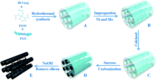
Herein, we report a general synthesis procedure for the ultrafine NiMoOx NPs confined in MC with a tunable pore structure and NiMo composition valence-state using SBA-15 as a hard template. First, the NiMoOx/SBA-15 catalysts were synthesized by co-impregnating Ni and Mo precursors into the mesochannels of SBA-15 (Scheme 1A–C). Second, NiMoOx/MC catalysts were prepared by the replication method using NiMoOx/SBA-15 as a hard template (Scheme 1C–E). The ultrafine NiMoOx NPs with diameters less than 2 nm were uniformly distributed on the mesochannel structure of the mesoporous carbon and had a high stability attributed to the confinement of the mesochannel. The bifunctional mechanism or electronic synergistic effects of Ni and Mo species for the reduction of 4-NP and other nitroarenes with different substituent groups were systematically investigated. A possible mechanism for the reduction of nitroarenes catalyzed by the NiMoOx bimetallic catalysts was also proposed.
2. Experimental
2.1 Materials
All chemicals were analytical grade reagents and used without further purification. Sucrose (C12H22O11), sodium hydroxide (NaOH), sodium borohydride (NaBH4), and ethanol (C2H6O) were obtained from Sinopharm Chemical Reagent Co. Ltd. Carbon disulfide (CS2) and p-nitrophenol (C6H5NO3) were purchased from Shanghai Macklin Biochemical Co. Ltd. Sulfuric acid (H2SO4) was purchased from Beijing Chemical Reagent Company.2.2 Synthesis of NiMoOx/MC catalysts with different morphologies
The mesoporous SBA-15 silica used as the template was synthesized according to the literature.28 The NiMoOx/SBA-15 catalysts with different morphologies were synthesized by the impregnation method. After impregnation, the samples were dried at 100 °C for 4 h and then calcined at 550 °C for 4 h. The procedure is shown in Scheme 1. For MC, a typical synthesis method was followed: 1.0 g of NiMoOx/SBA-15 was dissolved in 5 mL of water containing1.25 g of sucrose and 0.14 g of H2SO4. The mixture was stirred for 1 h and dried at 100 °C for 5 h. The mixture was then dried at 160 °C for 5 h. The obtained powder was mixed with a solution that included 0.8 g of sucrose and 0.14 g of H2SO4. The mixture was then heated at 100 °C for 5 h and dried at 160 °C for 5 h. The black powder was calcined under N2 atmosphere at 800 °C for 2 h. The resulting composite was added into a 2 M NaOH solution at room temperature to remove the silica. After filtration and washing, all samples were dried in an oven. The obtained catalysts were denoted as NiMoOx/MC-PL (NiMoOx/mesoporous carbon-platelet), NiMoOx/MC-SP (NiMoOx/mesoporous carbon-spherical), NiMoOx/MC-LR (NiMoOx/mesoporous carbon-long-rod), and NiMoOx/MC-HP (NiMoOx/mesoporous carbon-hexagonal-prism). For comparison, catalysts with different compositions were prepared by the same method, and were designated as NiO/MC-PL, MoO3/MC-PL, NiMoOx, and MC-PL. For further comparison, catalysts with different Ni/Mo valence-states were prepared by hydrogen reduction at different temperatures (450 °C and 750 °C) and CS2 vulcanization (referred to as NiMoOx/MC-PL-450, NiMoOx/MC-PL-750, and NiMoS/MC-PL, respectively).2.3 Catalyst characterization
The X-ray diffraction (XRD) patterns of the catalysts were characterized with a powder X-ray diffractometer (Shimadzu XRD 6000). The surface morphologies of the catalysts were obtained using an emission scanning electron microscope (SEM-SU8010). High-resolution transmission electron microscopy (HRTEM) and elemental mapping were performed with a Tecnai F20 instrument at 200 kV. The surface area and pore size were analyzed on a Micromeritics TriStar II 3020 analyzer. The oxidation states of the chemical species were characterized using a X-ray photoelectron spectrometer (XPS) on the PHI5000 Versaprobe system. The contents of Ni and Mo were obtained from an inductively coupled plasma mass spectrometer (ICP-MS, Thermo Scientific XSeries-2).The hydrogen temperature-programmed reduction (H2-TPR) was performed on a PCA-1200 instrument. The NiMoOx/MC-PL catalyst was pretreated under an Ar atmosphere (30 mL min−1) at 100 °C for 30 min. The samples were then reduced with 7% H2/Ar mixed gas (30 mL min−1) from 25 °C to 700 °C.
2.4 Catalyst measurements
The catalytic reduction of 4-NP over catalysts was carried out at room temperature, which was analyzed by a UV-Visible spectroscopy instrument (TU-1901). Freshly prepared NaBH4 solution (1.25 mL, 0.02 M), a certain amount of catalyst solution (1.25 mL, 0.4 mg mL−1), and 4-NP (25 μL, 0.012 M) were mixed together. Subsequently, the absorbance of the solution in the range of 200 to 500 nm was measured using an UV-Vis absorption spectrometer. The corresponding reduction equations are as follows:
 | (1) |
The conversion of 4-nitrophenol is expressed by
 | (2) |
 | (3) |
 | (4) |
Typically, in a glass reactor, a solution of the catalyst (0.5 g L−1, 1 mL), NaBH4 (0.4 mol L−1, 0.75 mL) and nitroarenes (1 mmol L−1, 8 mL) were stirred. The reaction was then quenched by adding NH4Cl solution and the reaction mixture was extracted with ethyl acetate. Subsequently, the mixture was dried using MgSO4. The product obtained was analyzed using gas chromatography (GC-2010 Plus, capillary column, KB-1) and gas chromatography-mass spectrometry (GC-MS, Thermo-Finnigan Trace DSQ coupled with a HP-5MS column).
3. Results and discussion
3.1 Characterization of the as-synthesized catalysts
The XRD patterns of different morphologies of the catalysts are displayed in Fig. S1† and 1. Fig. S1(a)† and 1(a) show the small-angle XRD patterns of NiMoOx/SBA-15 and the corresponding NiMoOx/MC. All samples displayed a sharp diffraction peak below 1.1° and two other peaks between 1.1° and 2.0° that can be indexed as (100), (110) and (200) diffraction signals associated with an ordered hexagonal mesostructure. The unchanged ordered structure was a good indication that the NiMoOx/MC material could be replicated from NiMoOx/SBA-15. In addition, compared with the XRD patterns of NiMoOx/SBA-15, the characteristic diffraction peaks attributed to the (100) in the XRD patterns of NiMoOx/MC shifted to the wide-angle direction, thus indicating that the pore size of NiMoOx/MC was smaller than that of NiMoOx/SBA-15.29 Fig. S1(b)† reveals the wide-angle XRD patterns of NiMoOx/SBA-15 catalysts. There was one broad peak between 20°and 30°for all the catalysts, which could be indexed to amorphous silica. One peak centered at 27.5° was attributed to the (011) crystal plane of MoO3 (JCPDS card 47-1320).30,31 Interestingly, the dispersion of MoO3 was different with respect to the support morphology changes. Among the four samples, the (011) peak intensity of MoO3 in NiMoOx/SBA-15-PL was higher than those of the other catalysts, which indicated that MoO3 had poor dispersibility in NiMoOx/SBA-15-PL. The wide-angle XRD patterns for NiMoOx/MC with different morphologies exhibited three main diffraction peaks, as illustrated in Fig. 1(b). One wide diffraction peak between 20° and 30° was attributed to carbon. The diffraction pattern at 14.3° originated from the NiMoO4 phase (JCPDS card 33-0948), which was ascribed to (110). Another diffraction pattern at 44.5° originated from metallic Ni (JCPDS card 04-0850), which was assigned to (111) of metal Ni.32,33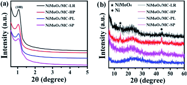 | ||
| Fig. 1 XRD patterns for various morphologies of NiMoOx/MC (a and b) in the small-angle and wide-angle. | ||
The surface morphology of the NiMoOx/MC catalysts was investigated by SEM, as shown in Fig. 2. The length and width of NiMoOx/MC-PL were ∼1075 nm and ∼350 nm, and those of the NiMoOx/MC-LR catalyst were ∼820 nm and ∼230 nm, respectively. Moreover, the length and width of NiMoOx/MC-HP were ∼755 nm and ∼530 nm, respectively. For NiMoOx/MC-SP, the particle diameter was measured to be ∼745 nm. From Fig. 2, it can be seen that these four catalysts retained the original morphology of their corresponding NiMoOx/SBA-15, indicating that the high calcination temperature did not destroy the structures of NiMoOx/SBA-15 during the replication process.
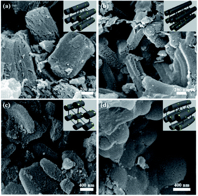 | ||
| Fig. 2 SEM images of as-prepared NiMoOx/MC catalysts with different morphologies. Note: (a) hexagonal prisms, (b) long rods, (c) platelets, and (d) sphericals. | ||
The TEM images and NiMoOx NPs size distribution histograms of NiMoOx/MC are shown in Fig. 3. From Fig. 3(a, d, g and j), it can be seen that all catalysts had a highly-ordered mesoporous structure, which was consistent with the small-angle XRD patterns. Importantly, ultrafine NPs were highly dispersed without any aggregation and well-encapsulated into the mesopores. As seen in the size distribution histograms, the average sizes of the NiMoOx NPs of NiMoOx/MC-HP, NiMoOx/MC-LR, NiMoOx/MC-PL, and NiMoOx/MC-SP were ∼0.97, ∼1.10, ∼1.37 and ∼1.65 nm, respectively. Furthermore, the corresponding elemental mapping images of Ni, Mo, and O for the NiMoOx/MC-PL and NiMoOx/MC-PL-450 catalysts are shown in Fig. 4, which reveal that the three elements were homogeneously distributed in the structure of the catalyst.34 The molar ratio of Ni to Mo was about 2, which was obtained from the TEM-EDS of NiMoS/MC-PL (Fig. S2†).
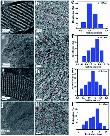 | ||
| Fig. 3 TEM images and NiMoOx particles size distribution histograms of NiMoOx/MC. Note: (a–c) NiMoOx/MC-HP, (d–f) NiMoOx/MC-PL, (g–i) NiMoOx/MC-LR and (j–l) NiMoOx/MC-SP. | ||
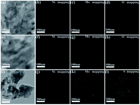 | ||
| Fig. 4 HRTEM images and the corresponding EDS elemental mapping images of (a–d) NiMoOx/MC-PL, (e–h) NiMoOx/MC-PL-450 and (i–l) NiMoS/MC-PL. | ||
The nitrogen adsorption–desorption isotherms, pore size distribution, and the corresponding parameters of the catalysts with different morphologies are displayed in Fig. 5 and Table 1. The nitrogen adsorption–desorption isotherms exhibited typical type IV patterns with hysteresis loops and capillary condensation, which indicated the presence of mesopores.35,36 The pore size distributions of NiMoOx/MC-PL and NiMoOx/MC-SP were about 4.0 nm, which indicated that the as-synthesized mesoporous materials had a uniform pore size distribution.37 As shown in Table 1, the surface area of NiMoOx/MC-PL was ∼995 m2 g−1, which was larger than those of NiMoOx/MC-HP, NiMoOx/MC-LR, and NiMoOx/MC-SP. Therefore, the NiMoOx/MC-PL catalyst provided a large surface area for the dispersion of the active sites. The average pore size of the NiMoOx/MC catalyst followed the order: NiMoOx/MC-LR (5.0 nm) > NiMoOx/MC-HP (4.5 nm) > NiMoOx/MC-PL (4.0 nm) > NiMoOx/MC-SP (3.9 nm).
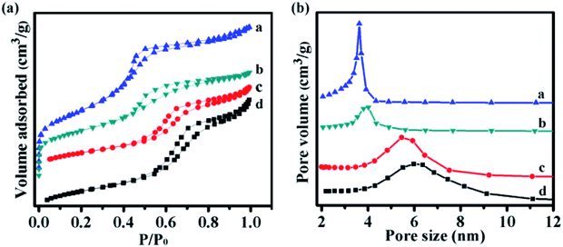 | ||
| Fig. 5 The N2 adsorption–desorption isotherms and pore size distribution of (a) NiMoOx/MC-PL, (b) NiMoOx/MC-SP, (c) NiMoOx/MC-HP, and (d) NiMoOx/MC-LR. | ||
| Samples | Dimensions (ca. nm) | SBETa (m2 g−1) | Smicb (m2 g−1) | Vmicc (cm3 g−1) | Vmes (cm3 g−1) | dBJHd (nm) |
|---|---|---|---|---|---|---|
| a BET surface area.b Calculated using the t-plot micropore area.c Calculated using the t-plot micropore volume.d Pore diameter was calculated with the BJH method. | ||||||
| NiMoOx/MC-PL | 1075 × 350 | 995 | 42 | 0.02 | 0.98 | 4.0 |
| NiMoOx/MC-LR | 820 × 230 | 795 | 360 | 0.19 | 0.81 | 5.0 |
| NiMoOx/MC-SP | 755 × 530 | 762 | 185 | 0.09 | 0.66 | 3.9 |
| NiMoOx/MC-HP | 745 × 745 | 673 | 298 | 0.15 | 0.61 | 4.5 |
The H2-TPR technique was used to study the reducibility of the Ni and Mo oxides on the support. The profiles are listed in Fig. 6. The profiles of the as-prepared catalysts exhibited two wide peaks in the 320–430 °C and 590–640 °C ranges.
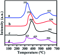 | ||
| Fig. 6 H2-TPR profiles of catalysts (a) NiMoOx/MC-PL, (b) NiMoOx/MC-LR, (c) NiMoOx/MC-HP and (d) NiMoOx/MC-SP. | ||
The first reduction peak was derived from nickel oxide and a portion of the molybdenum oxide. The second peak was ascribed to the second step reduction of MoOx. The different peak reduction temperatures were ascribed to the differences in the reducibility of the oxide. Compared to the Mo species, the Ni species was easier to reduce. According to the reference, the reduction peak for pure NiO (Ni2+ to Ni0) was centered around 350–400 °C38 and the reduction peak for MoO3 (Mo6+ to Mo4+) appeared at about 430 °C.39 Compared to pure NiO, the reduction peak of the different catalysts for the Ni species migrated to a lower temperature. This result was attributed to the phenomenon of hydrogen overflow from molybdenum oxide to nickel, which promoted the reduction of nickel oxide.40
XPS is a surface analytical technique that reveals information on the chemical state and surface composition of the catalysts. The XPS spectra and related parameters for NiMoOx/MC-PL, NiMoOx/MC-PL-450, NiMoOx/MC-PL-750, and NiMoS/MC-PL are displayed in Fig. 7 and Table S1.† The Ni 2p spectra showed four main peaks, which could be assigned to Ni0, NiO, Ni(OH)2, and the satellite signal.41,42 The ratio defined as Ni0/(Ni0+Ni2+) followed the order of NiMoOx/MC-PL-750 > NiMoOx/MC-PL-450 > NiMoOx/MC-PL, which correlated well with the H2-TPR spectra. The results showed that the content of metallic nickel and the active site increased with the increase in the reduction temperature. The Mo 3d XPS spectra for the different catalysts showed several pairs of corresponding peaks, which could be assigned to Mo6+, Mo4+, and metal Mo0. Compared to NiMoOx/MC-PL, the binding energy of Mo4+ and Mo6+ in NiMoOx/MC-PL-450 and NiMoOx/MC-PL-750 shifted to lower values, respectively, indicating that more unsaturation sites were generated. From Table S1,† the percentage of MoOx species, defined as (Mo6+ + Mo4+)/(Mo0 + Mo4+ + Mo6+), exhibited a significant change in different catalysts; it dropped from an initial of 88% to 63.7% with the increase in the reduction temperature. These results indicated that the molybdenum oxide on the surface of NiMoOx/MC was not completely reduced, even when the temperature was relatively high. In the case of NiMoS/MC-PL, the XPS peaks of Ni and Mo demonstrated the formation of the NiMoS nanocrystal.
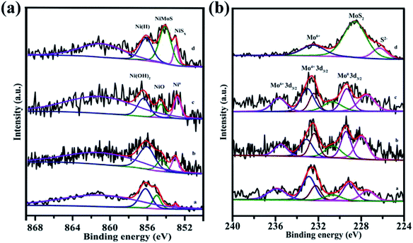 | ||
| Fig. 7 XPS spectra of Ni 2p and Mo 3d for different catalysts. Note: (a) NiMoOx/MC-PL, (b) NiMoOx/MC-PL-450, (c) NiMoOx/MC-PL-750, and (d) NiMoS/MC-PL. | ||
3.2 Catalytic activity towards the reduction of 4-nitrophenol
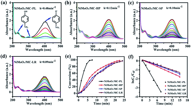
The catalytic performance of the catalysts was evaluated by the reduction of 4-nitrophenol (4-NP) in the presence of NaBH4. The reduction process of 4-NP was monitored by measuring the UV-Vis absorbance of the solution. According to the reference, the aqueous solution of 4-NP showed a strong absorption band at 317 nm. The absorption band shifted to 400 nm, when NaBH4 was added into the above solution, which indicated the formation of the nitrophenolate ion.43 The catalytic properties of NiMoOx/MC with different morphologies towards the reduction of 4-NP were comparatively studied, as displayed in Fig. 8. With the prolongation of the reaction time, the intensity of absorption peak at 400 nm decreased while another absorption band at 300 nm appeared.44 After the completion of the reaction, the peak corresponding to the nitrophenolate ion was not observed, revealing that 4-NP was completely reduced. From Fig. 8(e), it can be observed that the reaction times for the conversion of 50% of 4-NP to 4-AP in the presence of NiMoOx/MC-PL, NiMoOx/MC-HP, NiMoOx/MC-SP, and NiMoOx/MC-LR catalysts were 2.0 min, 6.6 min, 8.2 min, and 8.7 min, respectively. To qualify the reactivity, the reaction was regarded as a pseudo-first-order reaction. From Fig. 8(f), it can be observed that the reaction time is linear with respect to ln(Ct/C0), which was consistent with first order kinetics. In order to compare the catalytic performances of different catalysts, the rate constants, k (min−1) and K (min−1 g−1), and the value of TOF (s−1) of the catalysts were calculated. It can be found (Table 2) that the morphology of the catalysts had an important effect on the K and TOF values. Among the four different morphologies of the catalysts, the NiMoOx/MC-PL catalyst exhibited the highest K (960 min−1 g−1) and TOF (0.176 s−1) values. According to the HRTEM results, the size of the NiMoOx NPs of the catalysts was similar. Therefore, the difference in the catalytic activities of NiMoOx/MC-PL, NiMoOx/MC-HP, NiMoOx/MC-LR, and NiMoOx/MC-SP was mainly attributed to their different pore diameters, channel lengths, and surface areas. The NiMoOx/MC-PL catalyst had short channels, which shortened the diffusion route for the reactants in the pores. This made the reactants to have easier contact with the active sites, thus favoring 4-NP reduction. In addition, the NiMoOx/MC-PL catalyst exhibited a super catalytic performance owing to its large specific surface area (∼995 m2 g−1) and short channel length (∼351 nm). A larger specific surface area provided more attachment sites for NiMoOx NP and then increased the active sites. However, NiMoOx/MC-HP, NiMoOx/MC-LR, and NiMoOx/MC-SP catalysts had long channel lengths, which made 4-NP to diffuse for a longer period of time in contact with the active sites and therefore exhibited relatively inferior catalytic activities.| Samples | k (min−1) | K (min−1 g−1) | Ni loadinga (wt%) | TOFb × 103 (s−1) |
|---|---|---|---|---|
| a Determined by ICP-MS.b Calculated on the basis of total catalyst and a conversion rate of 50%. | ||||
| NiMoOx/MC-PL | 0.48 | 960 | 4.05 | 175.8 |
| NiMoOx/MC-HP | 0.12 | 240 | 3.2 | 69.3 |
| NiMoOx/MC-SP | 0.10 | 200 | 2.78 | 64.7 |
| NiMoOx/MC-LR | 0.09 | 180 | 3.37 | 49.9 |
| NiMoOx/MC-PL-450 | 0.65 | 1300 | 4.05 | 241.5 |
| NiMoOx/MC-PL-750 | 0.18 | 360 | 4.05 | 53.8 |
| NiMoS/MC-PL | 0.03 | 60 | 4.05 | — |
| NiO/MC-PL | 0.16 | 320 | 4.05 | 56.2 |
| MoO3/MC-PL | 0.002 | 4 | — | — |
| NiMoOx | 0.17 | 2073 | 24.7 | 103.8 |
| MC-PL | 0.001 | 2 | — | — |
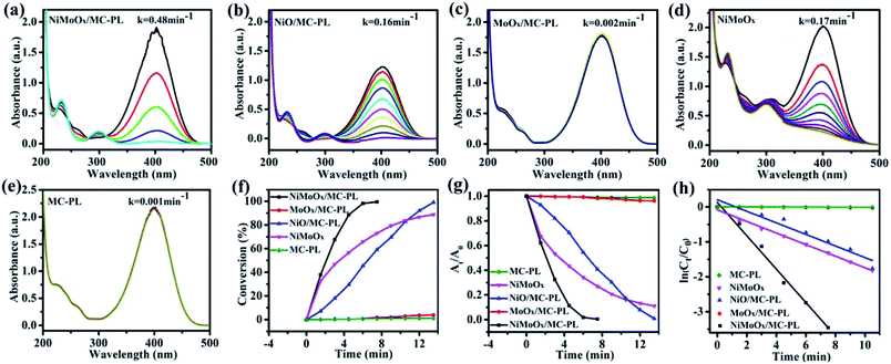
To further investigate the effect of composition on the reduction of 4-NP, the NiO/MC-PL, MoO3/MC-PL, NiMoOx and MC-PL catalysts were also prepared and compared with NiMoOx/MC-PL. For NiMoOx/MC-PL, NiO/MC-PL, and NiMoOx, the reaction times for the conversion of 50% of 4-NP were 2.0, 6.5 and 3.5 min in (Fig. 9), respectively. However, 4-NP displayed almost no change over the MoO3/MC-PL and MC-PL catalysts with the reaction time of 14.0 min, indicating that the sole Mo species and MC exhibited no activity for the 4-NP reduction. As shown in Table 2, the composition of the catalyst played an important effect on the values of K and TOF. The TOF values for these catalysts followed the order of NiMoOx/MC-PL (0.176 s−1) > NiMoOx (0.104 s−1) > NiO/MC-PL (0.056 s−1) > MoO3/MC-PL (0 s−1) = MC-PL (0 s−1). It was evident that the NiMoOx/MC-PL catalyst had the largest TOF, indicating that the Ni species in the NiMoOx/MC was the main active site, while the Mo species contributed to the performance of the Ni catalyst. Compared with NiMoOx/MC-PL, the NiMoOx catalyst exhibited almost no catalytic activity. The enhanced catalytic properties of the NiMoOx/MC-PL catalyst could be attributed to the synergistic effect of Mo and Ni species, as well as the strong interaction between the metal species and MC.
To further study the influence of valence-states of Ni and/or Mo on the catalytic performance, the NiMoOx/MC-PL catalyst was reduced by hydrogen at different temperatures.
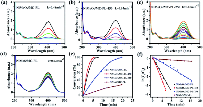
NiMoS/MC-PL was also prepared for comparison. It can be concluded from Fig. 10(e) that the conversion of 4-NP followed the order of NiMoOx/MC-PL-450 > NiMoOx/MC-PL > NiMoOx/MC-PL-750 > NiMoS/MC-PL. From Table 2, it can be found that the valence-states of the metal also played a great role in the K and TOF. The NiMoOx/MC-PL-450 catalyst had the largest K (1300 min−1 g−1) and TOF (0.242 s−1) values. Among these four catalysts, NiMoOx/MC-PL-450 exhibited the highest TOF value, which was attributed to the excellent synergistic effect between Ni and Mo species. According to the results of H2-TPR and XPS, after reduction at temperature 450 °C, most of the Ni species is converted to metallic nickel, while the MoOx species is still present. The results demonstrate that the metallic Ni had more activity than NiO towards the reduction of 4-NP. Moreover, metallic Ni and MoOx possessed the best synergistic effect for the reduction of 4-NP. With regard to the catalyst reduced at 750 °C, the proportion of Mo0 and Mo4+ species increased. However, the activity of NiMoOx/MC-PL-750 was lower than that of NiMoOx/MC-PL-450, clarifying that MoO3 could contribute more to the reduction properties of Ni compared to metallic Mo and MoO2. In addition, NiMoS/MC-PL showed a poor reaction rate, which indicated that the NiMoS species was less active than the corresponding metallic and oxidized NiMoOx species.
3.3 The effect of reaction parameters on the reduction of 4-NP
It is well known that the reaction rate of a chemical reaction is related to the concentration of reactants and other factors. In this research, the amount of catalyst and 4-NP as well as the concentration of NaBH4 were systematically studied. The concentration of NaBH4 was varied, while all other parameters were kept constant (the concentration of 4-NP was 12 mM and the amount of catalyst was 0.5 mg). From Fig. S3 and Table S2,† it can be seen that the reaction rate increased as the concentration of NaBH4 increased. Interestingly, the reaction rate increased rapidly as the concentration of NaBH4 ranged from 0.005 to 0.02 M, whereas the rate increased slowly as the concentration of NaBH4 ranged from 0.02 to 0.04 M. As we can see from the Table S2,† the variation tendency of TOF was similar to that of the rate constant as the concentration of NaBH4 changed. It is concluded that the reduction rate and TOF were closely related to the concentration of NaBH4.The effect of the amount of catalyst on the reduction of 4-NP is shown in Fig. S4 and Table S3.† It can be observed that k increased as the amount of catalyst increased. As seen in Fig. S4(h),† k was almost linear with respect to the amount of catalyst in the reaction system. This indicated that the increase in the catalyst amount resulted in more surface active sites. More chemical reactions then occurred, thus increasing the overall rate. The effect of the dosages of 4-NP on this reaction is shown in Fig. S5 and Table S4.† From Fig. S5(h),† it can be found that the reaction rate had a indirect relationship with the amount of 4-NP. The reaction rate decreased as the amount of 4-NP increased. This phenomenon can be ascribed to the Fig. S5(h),† it can be found that the reaction rate decreases as the amount of 4-NP increases. This phenomenon can be ascribed to the competition between the reactants and free sites on the surface of NiMoOx NPs. When reactants were adsorbed on the surface of the catalyst, the reaction occurred. In addition, adsorption of excessive reactants reduced the whole reaction rate.
3.4 The universal applicability of the NiMoOx/MC-PL-450 catalyst towards the reduction of nitroarene
In order to demonstrate the universal applicability of the NiMoOx catalyst in reducing the nitroarenes to aniline, various nitroarenes with different substituents were selected as the substrates.45 NiMoOx/MC-PL-450 was used as the catalyst and the results are listed in Table 3. NiMoOx/MC-PL-450 exhibited an efficient catalytic activity to selectively reduce nitroarenes with different functionalities. Almost no by-products were detected. The nitroarenes were converted to the corresponding amines in the yield of >84.0% (Table 3, entries 1, 3, 4, 5 and 6), while 4-nitroanisole and 2-amino-4-nitrotoluene showed a relatively low conversion (less than 70%) under the same conditions. The NiMoOx/MC-PL-450 catalyst demonstrated a high performance towards the reduction of nitroarenes under the optimized conditions. Therefore, the NiMoOx/MC-PL-450 catalyst is of great significance for the reduction of nitroarenes with different functional groups.| Entry | Substrate | Product | Time (min) | Conv. (%) | k (min−1) | K (min−1 g−1) | TOFb × 103 (s−1) |
|---|---|---|---|---|---|---|---|
| a Reaction conditions: catalyst (0.5 g L−1, 1 mL), nitroarenes (1 mmol L−1, 8 mL), NaBH4 (0.4 mol L−1, 0.75 mL), 600 rpm, room temperature.b The turnover frequencies (TOF) denote the moles of 4-NP converted per mole of Ni or Mo per second, calculated on the basis of total Ni and Mo loading in this research system. | |||||||
| 1 |  |
 |
10.0 | 97.2 | — | — | 37.6 |
| 2 |  |
 |
40.0 | 68.1 | 0.039 | 78 | 6.6 |
| 3 |  |
 |
10.0 | 97.5 | — | — | 37.7 |
| 4 |  |
 |
20.0 | 88.4 | 0.128 | 256 | 17.1 |
| 5 |  |
 |
10.0 | 99 | — | — | 38.3 |
| 6 |  |
 |
40 | 99 | 0.039 | 78 | 9.6 |
| 7 |  |
 |
40 | 61.5 | 0.018 | 36 | 6.0 |
| 8 |  |
 |
10.0 | 66.5 | 0.287 | 574 | 25.7 |
3.5 The proposed mechanism towards the reduction of nitroarenes
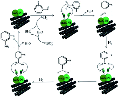
According to the above experimental results, the NiMoOx/MC-PL-450 catalyst exhibited a high performance, which was mainly ascribed to the synergistic effect between metal Ni and MoOx species. A possible mechanism was proposed towards the reduction of nitroarenes in the presence of NaBH4 over the NiMoOx/MC-PL-450 catalyst in Scheme 2.46 The typical steps are described below. First, the hydrolysis of NaBH4 produced active hydrogen and electrons that were adsorbed on the surface of the NiMoOx catalyst. Then, the active hydrogen was transferred from the surface of the NiMoOx catalyst to nitroarenes, which were adsorbed on the catalyst surface. Second, the nitroso intermediates were formed after the loss of water molecules. The intermediates were then rapidly reduced to a stable hydroxylamine. Finally, the final product amine was obtained by dehydroxylation of hydroxylamine and then desorption from the catalyst, which was the rate-determining step.4. Conclusions
In summary, the inexpensive NiMoOx catalysts confined in the mesoporous carbon with different morphologies and compositions were prepared using SBA-15 as a hard template with the replication method. For the catalysts with different morphologies, NiMoOx/MC-PL contributed to the dispersion of NiMoOx NPs and the diffusion of 4-NP owing to its large specific surface area and shorter channel length, exhibiting outstanding activity. For the catalysts with different metal valence states, the NiMoOx/MC-PL-450 catalyst showed the highest k (0.650 min−1) and TOF (0.242 s−1) values towards the reduction of 4-NP owing to the excellent synergistic effects of metallic Ni and MoOx species. The as-prepared NiMoOx/MC with efficient accessibility and suitable composition of the active sites illustrated a promising way for other reactions to design a novel non-noble catalyst.Conflicts of interest
There are no conflicts to declare.Acknowledgements
This study was supported by the National Natural Science Foundation of China (No. 21808079 and 21878121), Shandong Provincial Natural Science Foundation (Grant No. ZR2017BB029), China Postdoctoral Science Foundation (Grant No. 2017M610405), International Postdoctoral Exchange Fellowship Program between Helmholtz-Zentrum Berlin für Materialien und Energie GmbH, OCPC and University of Jinan.Notes and references
- N. Sahiner, S. Yildiz and H. Al-Lohedan, Appl. Catal., B, 2015, 166–167, 145–154 CrossRef CAS.
- M. Zhu, C. Wang, D. Meng and G. Diao, J. Mater. Chem. A, 2013, 1, 2118–2125 RSC.
- Z. Jiang, J. Xie, D. Jiang, X. Wei and M. Chen, CrystEngComm, 2013, 15, 560–569 RSC.
- Y. Peng, W. Leng, B. Dong, R. Ge, H. Duan and Y. Gao, Chin. J. Catal., 2015, 36, 1117–1123 CrossRef CAS.
- M. A. Oturan, J. Peiroten, P. Chartrin and A. J. Acher, Environ. Sci. Technol., 2000, 34, 3474–3479 CrossRef CAS.
- H. Hu, J. H. Xin, H. Hu and X. Wang, Nano Res., 2015, 8, 3992–4006 CrossRef CAS.
- W. Xiong, D. Sikdar, L. W. Yap, P. Guo, M. Premaratne, X. Li and W. Cheng, Nano Res., 2016, 9, 415–423 CrossRef CAS.
- U. Kurtan, M. Amir and A. Baykal, Chin. J. Catal., 2015, 36, 705–711 CrossRef CAS.
- C.-C. Yeh and D.-H. Chen, Appl. Catal., B, 2014, 150–151, 298–304 CrossRef CAS.
- J. Liang, X. Zhang, L. Jing and H. Yang, Chin. J. Catal., 2017, 38, 1252–1260 CrossRef CAS.
- J. P. Xiao, Y. Xie, R. Tang, M. Chen and X. B. Tian, Adv. Mater., 2001, 13, 1887–1891 CrossRef CAS.
- Q. Wang, W. Jia, B. Liu, A. Dong, X. Gong, C. Li, P. Jing, G. Xu and J. Zhang, J. Mater. Chem. A, 2013, 1, 12732–12741 RSC.
- S. Jian and Y. Li, Chin. J. Catal., 2016, 37, 91–97 CrossRef CAS.
- W. She, T. Qi, M. Cui, P. Yan, S. W. Ng, W. Li and M. Li, ACS Appl. Mater. Interfaces, 2018, 10, 14698–14707 CrossRef CAS PubMed.
- W. Gao, W. Li, Z. Xue, M. Pal, Y. Liu, C. Wang, J. Wang, S. Wang, X. Wan, Y. Liu and D. Zhao, New J. Chem., 2016, 40, 4200–4205 RSC.
- Y.-F. Jiang, C.-Z. Yuan, X. Xie, X. Zhou, N. Jiang, X. Wang, M. Imran and A.-W. Xu, ACS Appl. Mater. Interfaces, 2017, 9, 9756–9762 CrossRef CAS PubMed.
- H. Huang, X. Wang, X. Li, C. Chen, X. Zou, W. Ding and X. Lu, Green Chem., 2017, 19, 809–815 RSC.
- J. Fang, Y. Zhang, Y. Zhou, S. Zhao, C. Zhang, C. Yang, W. Chen, M. Huang and Y. Gao, Carbon, 2017, 121, 602–611 CrossRef CAS.
- J. Zhang, G. Chen, M. Chaker, F. Rosei and D. Ma, Appl. Catal., B, 2013, 132–133, 107–115 CrossRef CAS.
- S. Zhu, X. Lian, T. Fan, Z. Chen, Y. Dong, W. Weng, X. Yi and W. Fang, Nanoscale, 2018, 10, 14031–14038 RSC.
- K. Xu, W. Li, Q. Liu, B. Li, X. Liu, L. An, Z. Chen, R. Zou and J. Hu, J. Mater. Chem. A, 2014, 2, 4795–4802 RSC.
- D. Liu, X. Y. Quek, W. N. E. Cheo, R. Lau, A. Borgna and Y. Yang, J. Catal., 2009, 266, 380–390 CrossRef CAS.
- A. Ungureanu, B. Dragoi, A. Chirieac, C. Ciotonea, S. Royer, D. Duprez, A. S. Mamede and E. Dumitriu, ACS Appl. Mater. Interfaces, 2013, 5, 3010–3025 CrossRef CAS PubMed.
- H. Cheng, Y.-Z. Su, P.-Y. Kuang, G.-F. Chen and Z.-Q. Liu, J. Mater. Chem. A, 2015, 3, 19314–19321 RSC.
- Z. Weng, W. Liu, L.-C. Yin, R. Fang, M. Li, E. Altman, Q. Fan, F. Li, H.-M. Cheng and H. Wang, Nano Lett., 2015, 15, 7704–7710 CrossRef CAS PubMed.
- M. J. Mostazo-López, R. Ruiz-Rosas, A. Castro-Muñiz, H. Nishihara, T. Kyotani, E. Morallón and D. Cazorla-Amorós, Carbon, 2018, 129, 510–519 CrossRef.
- X. Duan, M. Xiao, S. Liang, Z. Zhang, Y. Zeng, J. Xi and S. Wang, Carbon, 2017, 119, 326–331 CrossRef CAS.
- D. Gao, A. Duan, X. Zhang, Z. Zhao, E. Hong, J. Li and H. Wang, Appl. Catal., B, 2015, 165, 269–284 CrossRef CAS.
- Z. Zhao, Y. Dai, J. Lin and G. Wang, Chem. Mater., 2014, 26, 3151–3161 CrossRef CAS.
- S. Badoga, K. C. Mouli, K. K. Soni, A. K. Dalai and J. Adjaye, Appl. Catal., B, 2012, 125, 67–84 CrossRef CAS.
- S. Wang, J. Wang, M. Zhu, X. Bao, B. Xiao, D. Su, H. Li and Y. Wang, J. Am. Chem. Soc., 2015, 137, 15753–15759 CrossRef CAS PubMed.
- H. Jung, B. Kim, S. Kim, H. Jang, N.-S. Lee, W. Kim and M. H. Kim, Mater. Lett., 2017, 204, 173–176 CrossRef CAS.
- W. Lu, Y. Song, M. Dou, J. Ji and F. Wang, Chem. Commun., 2018, 54, 646–649 RSC.
- Y. Sun, I. Sinev, W. Ju, A. Bergmann, S. Dresp, S. Kühl, C. Spöri, H. Schmies, H. Wang, D. Bernsmeier, B. Paul, R. Schmack, R. Kraehnert, B. R. Cuenya and P. Strasser, ACS Catal., 2018, 8, 2844–2856 CrossRef CAS.
- D. Saikia, Y.-Y. Huang, C.-E. Wu and H.-M. Kao, RSC Adv., 2016, 6, 35167–35176 RSC.
- Q. Wang, Z. Wang, T. Zheng, X. Zhou, W. Chen, D. Ma, Y. Yang and S. Huang, Nano Res., 2016, 8, 2294–2302 CrossRef.
- Y. Chi, L. Zhao, Q. Yuan, X. Yan, Y. Li, N. Li and X. Li, J. Mater. Chem., 2012, 27, 13571–13577 RSC.
- A. Alsalme, N. Alzaqri, A. Alsaleh, M. R. H. Siddiqui, A. Alotaibi, E. F. Kozhevnikova and I. V. Kozhevnikov, Appl. Catal., B, 2016, 182, 102–108 CrossRef CAS.
- Q. Bkour, K. Zhao, L. Scudiero, D. J. Han, C. W. Yoon, O. G. Marin-Flores, M. G. Norton and S. Ha, Appl. Catal., B, 2017, 212, 97–105 CrossRef CAS.
- N. Chen, S. Gong and E. W. Qian, Appl. Catal., B, 2015, 174–175, 253–263 CrossRef CAS.
- Y. Sun, C. Li and A. Zhang, Appl. Catal., A, 2016, 522, 180–187 CrossRef CAS.
- C. Chen, D. Yan, X. Luo, W. Gao, G. Huang, Z. Han, Y. Zeng and Z. Zhu, ACS Appl. Mater. Interfaces, 2018, 10, 4662–4671 CrossRef CAS PubMed.
- A. Gangula, R. Podila, R. M. L. Karanam, C. Janardhana and A. M. Rao, Langmuir, 2011, 27, 15268–15274 CrossRef.
- C.-H. Liu, J. Liu, Y.-Y. Zhou, X.-L. Cai, Y. Lu, X. Gao and S.-D. Wang, Carbon, 2015, 94, 295–300 CrossRef CAS.
- J. Hu, Y. Ding, H. Zhang, P. Wu and X. Li, RSC Adv., 2016, 6, 3235–3242 RSC.
- R. Nie, J. Wang, L. Wang, Y. Qin, P. Chen and Z. Hou, Carbon, 2012, 50, 586–596 CrossRef CAS.
Footnote |
| † Electronic supplementary information (ESI) available. See DOI: 10.1039/c8ra09026b |
| This journal is © The Royal Society of Chemistry 2019 |

