 Open Access Article
A novel microstructure inspired from Nepenthes alata and lizard skin and its enhanced uni-directional liquid spreading property†
Wenxi Sun ab,
Longjun Tang
 ab,
Wen Hong
 ab,
Yinjin Zhan
 ab,
Bin Yang
 ab and
Jingquan Liu
 *ab
*ab
aNational Key Laboratory of Science and Technology on Micro/Nano Fabrication, Shanghai Jiao Tong University, Shanghai 200240, China. E-mail: jqliu@sjtu.edu.cn
bCollaborative Innovation Center of IFSA, Department of Micro/Nano Electronics, Shanghai Jiao Tong University, Shanghai 200240, China
First published on 12th March 2019
Abstract
With the discovery of the liquid spreading mechanism on the peristome of Nepenthes alata, many studies focusing on uni-directional liquid spreading microstructures have been carried out with an emphasis on structural improvement and the spreading mechanism. Although there are various kinds of microstructures that can accomplish small-scale liquid uni-directional transportation, liquid spreading has not been optimized on a slope because of the unwanted backward flow generated by fabrication defects; inspired by the microstructure of the peristome surface of Nepenthes and the topography of the lizard skin, in this study, we present an innovative, easily processed microstructure that possesses the property of intensified uni-directional liquid spreading even on an oblique substrate. This property is derived from a new, hybrid mechanism that can significantly enhance the uni-directional liquid transportation.
Introduction
The wetting property of liquids on a solid surface is important for various settings that range from microfluidics, water harvesting, and inkjet printing to anti-icing1–8 and can be influenced by the chemical or physical properties of the solid surface.9,10 The wetting property includes isotropic wetting and anisotropic wetting. Compared with the isotropic wetting pattern, the anisotropic wetting pattern of liquids is less common and worthy of study. The mechanism of the anisotropic wetting characteristic generally lies in the continuity of surface energy in the major flow direction, whereas the surface energy is incontinuous in the minor direction.11,12 The recently reported studies on the anisotropic wetting property are mainly focused on the means of chemical coating and microstructures;13,14 according to these studies, the macroscopical wetting characteristic of liquids can be affected by the microfluidics formed on the surface of the microstructure, which may satisfy many applications; as a result, exploration of an efficient microstructure manufacturing method to gain special wetting properties definitely has a potential value.The uni-directional wetting phenomenon is a special type of anisotropic wetting in which a droplet placed randomly only spreads to one side rather than both sides; in recent years, numerous studies have been carried out to achieve the uni-directional liquid wetting property on solid surfaces; the related approaches include different hydrophilic structures with chemical coatings,15 slanted micro-pillar arrays,16–18 nonparallel plates,19,20 asymmetrical arrays,21,22 etc. Most of these cases are based on the hydrophilic characteristic differences or pressure differences on two sides of the liquid. With the revelation of the surface microstructure on the peristome of Nepenthes alata by Dr Jiang Lei, an outstanding uni-directional liquid wetting property with a novel mechanism has attracted worldwide attention.23 The specialty of the extraordinary mechanism lies in that in the forward direction, the liquid speedily moves in/along the interior corners of the microstructure based on the interior corner flow theory.24 On the other hand, in the backward direction, the liquid will be pinned at the reentrant (shown in Fig. 1) due to the incontinuous surface energy. In the lateral direction, the liquid is guided in straight microgrooves.25–27 This novel microstructure can be applied in various fields, such as water-collection, self-lubrication, and nonpowered delivery of medicine, of liquid controlling. However, the complete imitation of this composite three-dimensional microstructure still remains a challenge due to its complexity.
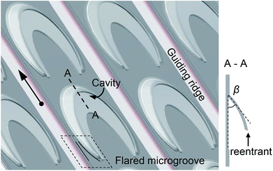 | ||
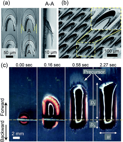
| Fig. 1 Design of the microstructure with flared microgrooves. The left arrow indicates the forward (major) direction. The section view is shown as A–A. | ||
Inspired by the peristome microstructure of the plant, a microstructure that can achieve uni-directional liquid spreading should include the following factors: the interior corner array formed by two layers enhances the forward directional flow; a reentrant structure leads to incontinuous surface energy such that the liquid can be restrained in the backward direction; and the guiding ridges prevent the liquid from spreading laterally. Note that the liquid can spread in the interior corners at a significant speed. This wetting phenomenon can be further optimized by adjusting the structural parameters of the interior corner. For the pinning effect in the backward direction, due to the potential but unwanted manufacturing defects and errors, or the relatively large gravity of the liquid droplet, the liquid can easily collapse at the reentrant and obviously flow backwards. This may weaken the effect of the uni-directional liquid spreading.
In this study, to easily achieve uni-directional liquid spreading, a novel, hybrid biomimetic microstructure is demonstrated along with two mechanisms of the uni-directional liquid spreading. At first, inspired by the peristome surface microstructure of Nepenthes alata, arcuate chamber arrays were fabricated to enhance the forward liquid spreading and achieve backward pinning at the reentrant. Then, based on the integument microstructure of a kind of lizard,22,28,29 a flared microgroove was integrated into the structure to further impede the backward flow and reduce the difficulty of manufacturing. This microstructure, possessing the ability of uni-directional liquid spreading, was fabricated by a surface micro-machining process. Moreover, its property of uni-directional liquid spreading was demonstrated, as shown in Fig. 2c. The effects of the impedance of the backward flow on two microstructures, with and without the flared microgrooves, were compared, and the results showed that on the hybrid microstructure, the liquid could even spread uphill. In addition, studies on the effect of different interior corner angles are manifested.
Results and discussion
Characterization of the microstructure with flared grooves and its comparison with the microstructure without flared grooves
To imitate the peristome microstructure of Nepenthes alata and endow it with the property of uni-directional liquid spreading, based on the abovementioned pivotal factors, the microstructure of a biomimetic film was mainly designed in three parts. In particular, a semi-closed lunate cavity array with interior corners should be included, such that the liquid can spread forward through these interior corners by capillary force. Then, a reentrant or an asymmetrical structure should be included to achieve liquid pinning in the backward direction. At last, guiding ridges that prevent the liquid from spreading laterally should be added. By mixing all these elements, a novel microstructure on which the liquid can successfully spread upwards is presented. As shown in Fig. 1, the cavities consist of two layers of a thin polymer film forming the interior corner. If the interior corner angle satisfies the Concus–Finn condition,30 the liquid can quickly spread in the major direction according to the interior corner flow theory. In the opposite direction, besides the reentrant that can pin the liquid by contact angle hysteresis,31 the flared microgrooves constituted by the bottom end of the cavity and guiding ridges can also slow down the backward flow by reducing the pressure difference22,32 on the pinning line. Moreover, a surface micro-machining process was applied, as shown in Fig. S1.† After the first parylene layer was deposited, a sacrificial photoresist (PR) layer was spin-coated on it, followed by a photolithography process with an enlarged exposure gap such that the edge of the PR profile emerged as a slope. Then, the second layer of parylene was deposited and etched. Finally, the PR layer was released, and the interior corner was formed by two polymer layers.After the fabrication, an ultrathin film (thickness < 20 μm) with oval-like cavities and guiding ridges could achieve the function of uni-directional liquid transportation. The width of one cavity was about 120 μm, and the length was about 150 μm. The width of the guiding ridges was about 30 μm. The thickness of the whole structure was 13 μm. The SEM images, as shown in Fig. 2a and b, exhibit the profile and details of the microstructure with flared grooves. The thin film can also be peeled off from the substrate and attached on a curved substrate; this emphasizes the flexibility of this film. Ethyl alcohol + DI water were used at different concentrations for tests to obtain different contact angles (CAs) when the liquid was placed on the biomimetic film. Fig. 2c and Video 1 (ESI†) show that at a proper concentration, the liquid can spontaneously and uni-directionally spread on the film.
To demonstrate the characteristics of the microstructure with flared grooves that can make the liquid transport upwards, the ability of the microstructure with and without flared microgrooves has been compared, as shown in Fig. 3.
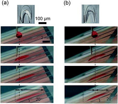
The SEM images shown in the upper part of Fig. 3 demonstrate the morphology characteristics of two structures produced by the same manufacturing process. Notably, the microstructure with flared grooves has an oval-like shape cavity forming a flared groove with the guiding ridge, whereas the microstructure without flared grooves has a forked tail cavity forming a tapered groove with the guiding ridge. To show the distinction of uni-directional liquid transportation property on these two structures, the substrate was inclined at 20 degrees, and a 4 μL droplet was vertically placed on the two microstructures.
As shown in Fig. 3a and b, it is clear that on the microstructure with flared grooves, the liquid can spread uni-directionally in an upward direction without obvious backward flow (ESI Video 2†). However, on the microstructure without flared grooves, the liquid will obviously leak backwards (ESI Video 3†). These results suggest that the microstructure with flared grooves not only can transport the liquid in the forward direction, but can also effectively impede the backward leaking flow when compared with the microstructure without flared grooves; thus, the microstructure with flared grooves can accomplish the purpose of liquid uphill spreading.
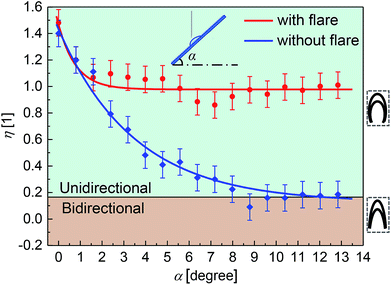
Experiments were performed to further clarify the distinction in these two microstructures. The test was carried out by setting different tilt angles of the substrate from 0 to 13 degrees and determining the behavior of the liquid droplets on these two microstructures. The results are shown in Fig. 4.
The ratio η is used to describe the uni-directional liquid spreading extent, making the comparison easier, which is defined as
 | (1) |
![[thin space (1/6-em)]](https://www.rsc.org/images/entities/char_2009.gif) α is used to correct the real spreading distance. Since the droplets were manually placed by a needle during one test, the volume of the droplets might vary. This may lead to differences in Df or Dh due to different gravities of the droplets and undoubtedly lead to differences in W due to different diameters of the droplets. For this reason, the extent of uni-directional spreading that is only described by Df − Dh may be inaccurate for comparison. Thus, the ratio η was used to compensate for the inaccuracy caused by different volumes of the liquid droplets.
α is used to correct the real spreading distance. Since the droplets were manually placed by a needle during one test, the volume of the droplets might vary. This may lead to differences in Df or Dh due to different gravities of the droplets and undoubtedly lead to differences in W due to different diameters of the droplets. For this reason, the extent of uni-directional spreading that is only described by Df − Dh may be inaccurate for comparison. Thus, the ratio η was used to compensate for the inaccuracy caused by different volumes of the liquid droplets.
In the test results shown in Fig. 4, the red dots represent the performance of the microstructure with flared grooves, and the red line is the corresponding fitting curve, which is nicely maintained at the same level as the tilt angle of the substrate increases. The blue dots represent the performance of the microstructure without flared grooves, and the blue line is the corresponding fitting curve. Although the effect of forward liquid spreading may be better in a small slope situation, it sharply declines as the gradient increases. When α is approximately 9°, the ratio η becomes negative, which means more liquid spreads reversely. In other words, the effect of liquid uni-directional spreading vanishes and is substituted by bidirectional spreading. These results emphasize the effect that the backward liquid flow can be impeded on the microstructure with flared grooves. Moreover, the microstructure with flared grooves can maintain the uni-directional liquid spreading property on a slope, whereas the microstructure without flared grooves can only be applied on a flat surface.
Liquid backflow impeding mechanism on the microstructure with flared grooves
When a liquid is spread on a microstructure, the backward leaking problem always exists. This phenomenon prevents the liquid from climbing upwards, also impeding the development of a uni-directional liquid spreading microstructure.The reason why the liquid leaks in the backward direction can be explained by the following two aspects. On the one hand, limited by the fabrication method and material, the manufacturing deficiency will lead to the formation of extremely narrow channels that can be regarded as numerous capillaries. As a result, the liquid will leak backwards through these capillaries at a significant speed. On the other hand, when the substrate is oblique, caused by gravity, the droplet is more likely to collapse at the reentrant; thus, the effect of pinning will be reduced as well.
The microstructure with flared grooves holds back the downward liquid via a hybrid mechanism and possesses splendid efficiency. Except the mechanism concerning the pinning effect at the reentrant that has been already discussed in another study,31 this newly designed structure possesses a unique mechanism to prevent the liquid from leaking backwards. Due to the flared shape, the width of the grooves increases in the backward direction; this is obviously distinct from the case of the microstructure without flared grooves. This distinction between the two structures can lead to an opposite effect when the liquid spreads on them.
According to the well-known Young–Laplace equation,
| ΔP = γ(R1−1 + R2−1) | (2) |
Although there are structural differences between the ridges on flat surfaces and the two plates, the abovementioned theory can still be used; similar to the theory mentioned in a study on a micro-machining biomimetic lizard skin microstructure,28 the speculation of the presence of ridges on a flat surface as a capillary channel with an infinite depth (R1 = R, R2 → ∞) can be rational; thus, the expression can be simplified as
| ΔP = γR−1 | (3) |
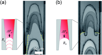
Based on this theory, in the case of the microstructure without flared grooves, as liquid spreads to a narrow lane, Rb will become significantly smaller. According to eqn (3), the additional force will be enlarged along with ΔPb. As a consequence, the liquid has a trend to move to narrower lanes step by step where the additional force will be larger; just like the liquid is being squeezed out. The image in Fig. 5a shows the severity of the liquid backward leaking.
On the contrary, the flow of the liquid prefers to slow down on the microstructure with flared grooves. Since Ra becomes larger as the liquid transports backwards, the additional force becomes smaller along with ΔPa. Moreover, the resistance along the increasing pinning line becomes stronger. As shown in Fig. 5b, instead of leaking for a long distance, the liquid just stops at the bottom of the spreading unit. In other words, on the microstructure with flared grooves, the flow of the liquid will gradually slow down beforehand in the backward direction.
The liquid on the microstructure without flared grooves has a tendency to leak backwards; this means that the property of uni-directional liquid spreading on this structure is negligible. However, the microstructure with flared grooves can theoretically and practically impede the backward flow.
Liquid forward spreading mechanism
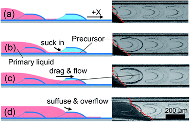
During the tests, there was a visible precursor film that appeared in front of the visual contact line on both sides, as is marked by the arrow in Fig. 2c. Importantly, the precursor film is considered to lead the primary droplet and make the liquid slip more smoothly; this means that the liquid actually spreads on the precursor film. Similar to the microstructure of the peristome, the interior corner formed by the two layers of parylene-C will immediately suck in the liquid driven by capillary force and form a precursor film in the forward direction if the liquid CA and interior corner angle satisfy the Concus–Finn condition:30| θc ≤ π/2 − β/2 | (4) |
This inequation means that if the critical CA is large enough and β is pretty small, the interior corner can easily become wet. Then, in the flow direction, the liquid will more likely spread over a long distance. As a result, decreasing the interior corner angle β is an efficient way to make the liquid spread easily in the forward direction.
The process of liquid spreading is observed by a CCD camera, and the slow-motion images are demonstrated in Fig. 6 accompanied by schematics. When the liquid reaches the tail of one spreading cavity (Fig. 6a), the interior corner is immediately wetted by the liquid under capillary force, and the precursor appears at very short time (Fig. 6b). With the formation of the precursor film, the cavity is then gradually filled with liquid as the primary droplet is led to the current cavity (Fig. 6c). Finally, after the liquid suffuses the first spreading cavity, it will overflow and spread to the next spreading cavity (Fig. 6d). Since the formation and spreading speed of the precursor are much faster than those of the primary droplet, the precursor can be visible.
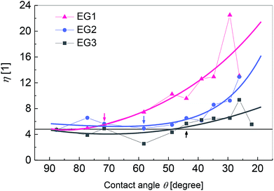
As the abovementioned spreading procedure suggests, the formation of the precursor film mainly depends on the angle of the interior corner constructed by two layers of the structural film. If the precursor appears, a droplet can successfully spread in the forward direction. The uni-directional spreading effect under different experimental conditions was demonstrated. If the exposure gap (EG) is enlarged, the interior corner angle β will be smaller due to the scattering of the UV light. The experimental data with respect to the slope of the PR profile is shown in Fig. S2 and Table S1.† Since β is important for the formation of a precursor film, we speculate that under different β conditions, the liquid will behave differently on the structure. The extent of variation in the uni-directional liquid spreading with different hydrophilicities (different CAs) was then compared under three conditions with different β, and the result is shown in Fig. 7. Alcohol + DI water were used at different concentrations to obtain different CAs on the parylene-C film, and the corresponding CAs were measured by an optical microscope at ambient temperature, which were approximately 86–36°.
Under the conditions of the same interior corner angle β, as one single line in Fig. 7, if the liquid is hydrophilic enough to the substrate (i.e. the CA is small enough), the precursor appears, and the droplet starts to spread uni-directionally.
As β becomes smaller, the precursor film forms more easily (the CA is bigger when the precursor forms); this is consistent with the abovementioned speculation. As shown in Fig. 7, when the exposure gap is 250 μm (EG1), the angle of the interior corner measured by a step profiler is about 36° (β ≈ 36°), and the liquid starts to spread at the concentration of 18%; this is marked by a red arrow (CA ≈ 71.61°). Similarly, when the exposure gap is 100 μm (EG2, β ≈ 55°), the liquid starts to spread at the concentration of 25% (CA ≈ 58.28°, marked by a blue arrow). When the exposure gap is 20 μm (EG3, β ≈ 85°), which is used in standard photolithography processes, the liquid starts to spread at the concentration of 35.71% (CA ≈ 45°, marked by the black arrow).
In Fig. S3,† the appearance of the precursor is more apparent, which is marked by arrows in Fig. 7. The purple squares represent that the precursor does not appear; thus, the effect of the uni-directional liquid spreading is inconspicuous. On the other hand, the orange triangles represent the appearance of the precursor film; this also means that the liquid can obviously spread uni-directionally. The straight line across the graph and the green zone indicate the area of the inequation (4). It can be summarized that when the precursor appears at first, the interior corner angle β and the critical CA θc satisfy the Concus–Finn condition approximately. Although the results have some deviation due to the roughness of the structure, these data show that the results of the experiments are consistent with the speculation that the range of the CA θ to achieve uni-directional liquid spreading will be enlarged if the interior corner angle β of the interior corner becomes smaller. In other words, a small interior corner angle β allows the liquid to more easily spread uni-directionally.
Experimental
Fabrication of the film with a microstructure with flared grooves
The biomimetic film was fabricated based on the surface micro-machining technology. The entire film was fabricated on a glass slide substrate. The microstructure was mainly constructed by two layers of parylene-C membrane and photoresists (PR, AZ 4620) sealed in the middle of the two layers. The glass slide acted as the hard substrate, the parylene membrane acted as the structural layers and the photoresists acted as a mold to form the topography of the microstructure.First parylene membrane
A glass slide was prepared by ultrasonication for 15 min in acetone, 15 min in ethanol and 10 min in DI water for cleaning, followed by drying at 180 °C for 2 hours such that the adhesion of the parylene membrane to the substrate was improved. The parylene membrane was then deposited (PDS 2010, SCS, USA) on the glass slide. Then, 4.5 g p-xylylene dimer was placed in the CVD machine and vaporized at about 170 °C. Then, the gasified dimer was heated to 680 °C such that the dimer was converted to a monomer. Finally, the monomer polymerized after the temperature was decreased to 145 °C, and a 5 μm parylene-C was deposited on the glass substrate as the first structural layer (Fig. S3a, ESI†).Photoresist sacrifice layer
A 10 μm photoresist (PR, AZ 4620) layer was spin-coated (Karl Suss RC6) on the first parylene membrane and baked for 5 h at 90 °C until its solidification. A lithography process (Karl Suss MA6) with an enlarged exposure gap was used to make the cross section of the photoresist a trapezoid. The exposure gaps in fabrication were 250 μm, 150 μm, and 20 μm, and the gradient of the PR cross section was 35.7°, 57.7°, and 85.9°, respectively (Fig. S1, ESI†). The exposure process lasted for 45 s with the UV exposure of 800 mJ cm−2, and the development process lasted for 2 min 40 s. An RIE treatment was used to remove the residual PR followed by curing 4 times for 1 min with a 450 mL min−1 oxygen flow rate. After this, a heating treatment was conducted at 85 °C for 8 min on a hot plate to make the surface of the PRs smoother (Fig. S3b, ESI†).Second parylene membrane
The process was similar to that of the first parylene membrane, except for the quantity of the material. Herein, 2.7 g p-xylylene dimer was used to obtain a parylene-C membrane of 3 μm.Etching process
A 15 μm photoresist layer was spin-coated on the second parylene membrane followed by baking for 8 h at 90 °C until solidification. Then, the sample was treated via a standard lithography process to form a mask for etching. The exposure lasted for 80 s with the UV exposure of 1400 mJ cm−2, and the development lasted for 4 min. Then, the sample was etched by the RIE treatment. The oxygen plasma was used for etching, and the gas flow was 100 mL min−1. The second layer of the parylene membrane was treated for 12 min with the power of 80 W until it was totally removed. Then, the PRs in the spreading units were released with a dip in acetone for 20 s. The sample was cleaned with a dip in ethanol for 10 s and in DI water for 10 s (Fig. S3c and d, ESI†).Conclusions
In this study, a novel microstructure inspired by the peristome of Nepenthes alata and lizard skin is presented. This microstructure has innovative flared grooves to prevent the droplets from leaking backwards. The liquid droplets can spread uni-directionally on this microstructure and even spread uphill against gravity based on a hybrid mechanism. The surface microstructure can be simply fabricated with biocompatible polymers. The effect of the microstructure with flared grooves is demonstrated at the macro- and micro-level. The integrated mechanism of the backward and forward liquid spreading has been provided in brief. This biomimetic microstructure with a novel profile possesses biocompatibility, ease of production, and unique wetting features and thus may satisfy various applications, for example, as a pressure-relief valve or a cell trapping device, in microfluidic devices and biomedical engineering.Conflicts of interest
There are no conflicts to declare.Acknowledgements
This work was partially funded by the National Key R&D Program of China under grant 2017YFB1002501, the National Natural Science Foundation of China (No. 51475307, 61728402), Research Program of Shanghai Science and Technology Committee (17JC1402800, 15JC1400103), Program of Shanghai Academic/Technology Research Leader (18XD1401900), ZBYY-MOE Joint Funding (6141A02022604) and China Scholarship Council (201606230100). The authors are grateful to the Center for Advanced Electronic Materials and Devices (AEMD) of Shanghai Jiao Tong University.Notes and references
- H. A. Stone, A. D. Stroock and A. Ajdari, Annu. Rev. Fluid. Mech., 2004, 36, 381–411 CrossRef.
- M. K. Chaudhuty, A. Chakrabarti and S. Daniel, Langmuir, 2015, 31, 34 Search PubMed.
- R. Seemann, M. Brinkmann, T. Pfohl and S. Herminghaus, Rep. Prog. Phys., 2012, 75, 016601 CrossRef PubMed.
- S. N. Zhang, J. Y. Huang, Y. Cheng, H. Yang, Z. Chen and Y. K. Lai, Small, 2017, 13, 48 Search PubMed.
- K.-C. Park, P. Kim, A. Grinthal, N. He, D. Fox, J. C. Weaver and J. Aizenberg, Nature, 2016, 531, 7592 CrossRef PubMed.
- J. Z. Wang, Z. H. Zheng, H. W. Li, W. T. S. Huck and H. Sirringhaus, Nat. Mater., 2004, 3, 3 CrossRef PubMed.
- S. Daniel, M. K. Chaudhury and J. C. Chen, Science, 2001, 291, 5504 CrossRef PubMed.
- M. J. Kreder, J. Alvarenga, P. Kim and J. Aizenberg, Nat. Rev. Mater., 2016, 1, 1 Search PubMed.
- T. Y. Liu and C. J. Kim, Science, 2014, 346, 6213 Search PubMed.
- S. N. Zhang, J. Y. Huang, Z. Chen and Y. K. Lai, Small, 2017, 13, 3 Search PubMed.
- Y. Chen, B. He, J. Lee and N. A. Patankar, J. Colloid Interface Sci., 2005, 281, 2 Search PubMed.
- D. Y. Xia, L. M. Johnson and G. P. López, Adv. Mater., 2012, 24, 10 CrossRef PubMed.
- Y. Zhao, Q. H. Lu, M. Li and X. Li, Langmuir, 2007, 23, 11 Search PubMed.
- X. M. Dai, N. Sun, S. O. Nielsen, B. B. Stogin, J. Wang, S. K. Yang and T. S. Wong, Sci. Adv., 2018, 4, 3 Search PubMed.
- P. Ge, S. L. Wang, W. D. Liu, T. Q. Wang, N. Z. Yu, S. S. Ye, H. Z. Shen, Y. X. Wu, J. H. Zhang and B. Yang, Langmuir, 2017, 33, 9 Search PubMed.
- K. H. Chu, R. Xiao and E. N. Wang, Nat. Mater., 2010, 9, 5 CrossRef PubMed.
- P. Guo, Y. M. Zheng, C. C. Liu, J. Ju and L. Jiang, Soft Matter, 2012, 8, 6 Search PubMed.
- X. M. Yang, Z. W. Zhong, E. Q. Li, Z. H. Wang, W. Xu, S. T. Thoroddsen and X. X. Zhang, Soft Matter, 2013, 9, 46 Search PubMed.
- C. Luo, X. Heng and M. M. Xiang, Langmuir, 2014, 30, 28 Search PubMed.
- X. Heng and C. Luo, Langmuir, 2015, 31, 9 CrossRef PubMed.
- K. C. Park, P. Kim, H. He and J. Aizenberg, Nature, 2016, 531, 7592 CrossRef PubMed.
- M. Yenmis, D. Ayaz, W. C. Sherbrooke and M. Vesely, Zoomorphology, 2016, 135, 1 CrossRef.
- H. W. Chen, P. F. Zhang, L. W. Zhang, H. L. Liu, Y. Jiang, D. Y. Zhang, Z. W. Han and L. Jiang, Nature, 2016, 532, 85–89 CrossRef CAS PubMed.
- M. M. Weislogel, J. Fluid Mech., 1998, 373, 349–378 CrossRef.
- C. X. Li, N. Li, X. S. Zhang, Z. C. Dong, H. W. Chen and L. Jiang, Angew. Chem., 2016, 55, 48 CrossRef PubMed.
- H. W. Chen, L. W. Zhang, P. F. Zhang, D. Y. Zhang, Z. W. Han and L. Jiang, Small, 2017, 13, 4 Search PubMed.
- H. W. Chen, L. W. Zhang, Y. Zhang, P. F. Zhang, D. Y. Zhang and L. Jiang, J. Mater. Chem. A, 2017, 5, 6914 RSC.
- P. Comanns, G. Buchberger, A. Buchsbaum, R. Baumgartner, A. Kogler, S. Bauer and W. Baumgartner, J. R. Soc., Interface, 2015, 12, 109 CrossRef PubMed.
- G. Buchberger, F. Hischen, P. Comanns, R. Baumgartner, A. Kogler, A. Buchsbaum, S. Bauer and W. Baumgartner, Procedia Eng., 2015, 120, 106–111 CrossRef CAS.
- P. Concus and R. Finn, Proc. Natl. Acad. Sci. U. S. A., 1969, 63, 2 CrossRef.
- J. Q. Li, X. F. Zhou, J. Li, L. F. Che, J. Yao, G. Mchale, M. K. Chaudhury and Z. K. Wang, Sci. Adv., 2017, 3, 10 Search PubMed.
- M. Praskash, D. Quéré and J. W. M. Bush, Science, 2008, 320, 5878 Search PubMed.
Footnote |
| † Electronic supplementary information (ESI) available: Video 1: uni-directional liquid spreading on flat microstructure. Video 2: liquid spreads uphill on microstructure with flared grooves. Video 3: liquid uphill spreading loses efficacy on microstructure without flared grooves. See DOI: 10.1039/c8ra08768g |
| This journal is © The Royal Society of Chemistry 2019 |

