 Open Access Article
Modification of 3D printed PCL scaffolds by PVAc and HA to enhance cytocompatibility and osteogenesis
Jingqi Ma ,
Lili Lin,
Yi Zuo
 *,
Qin Zou,
Xin Ren,
Jidong Li and
Yubao Li*
Research Center for Nano-Biomaterials, Analytical & Testing Center, Sichuan University, Chengdu 610064, P. R. China. E-mail: zoae@scu.edu.cn; nic7504@scu.edu.cn; Fax: +86 28 85418178; Tel: +86 28 85418178
First published on 12th February 2019
Abstract
In the study, a specific material system that contains poly-(ε-caprolactone) (PCL), polyvinyl acetate (PVAc) and hydroxyapatite (HA) was used to fabricate porous scaffolds employing a 3D printing technique for bone regeneration. Four groups of 3D printing scaffolds were fabricated: PCL, PCL/PVAc, PCL/HA and PCL/PVAc/HA for comparision. The morphologies, mechanical properties and biological characteristics of these scaffolds were analyzed using SEM, a material testing machine, in vitro cell culture and in vivo animal experiments. The results showed that these 3D printed scaffolds possessed porous channel structures with a hole size of 375–475 μm and porosity of 74.1–76.1%. The compressive moduli of the scaffolds increased with the addition of HA and decreased with the addition of PVAc. The PCL/PVAc/HA scaffold exhibited higher cell proliferation and bone formation rates than other groups (p < 0.001), which could be attributed to the synergistic effect of PAVc and HA components. Two types of new bone formation patterns in the scaffold were found in this study: one is the new bone formed directly on the grid matrix, and the other is the new bone initially formed in the center of the scaffold channel and then remolded to concentric circles. The osteogenesis pattern of the latter is analogous to the osteon structure of a cortical bone. The 3D printed scaffold based on PCL/PVAc/HA tri-component system is a promising prospect for future individualized bone repair applications.
Introduction
Treatments for bone defects have been developed for centuries. Although autografts are widely used by clinicians, they have many drawbacks, such as lack of sufficient bone sources, damaged donor sites and complications due to second surgery.1 In response, artificial bone repairing materials have emerged and partly solved the problems of autografts. However, current processing and biomaterials are still difficult to meet with the requirement of individual-based treatment, e.g., uniform bone repair materials are difficult to meet the treatment needs of different size and shape defect sites.2 Development of 3D printing as a fast additive manufacturing technique offers a new choice for material scientists and orthopaedic surgeons. Scaffolds can be modelled layer by layer with appropriate materials according to the designed framework or the reconstruction of the CT scan data of bone defects.3,4 With the help of 3D printing technology, clinicians can fabricate scaffolds of different size, specific shape and porosity.The necessary bridge linking 3D printing to the clinic is an appropriate matrix material. Poly-(ε-caprolactone) (PCL), a biocompatible polymer, has been approved by the Food and Drug Administration of USA.5 The PCL polymer exhibits high crystallinity and a low melting point, as well as superior workability and machinability at normal temperature.6 Presently, PCL is used for production of surgical sutures, screws for fracture fixation, cranial repair materials, and sustained-release systems.7,8 PCL has also been employed as a 3D printing matrix to prepare scaffolds of combined hydroxyapatite (HA) particles, for which PCL matrix provides flexible support and HA provides strength and bioactivity.5,9,10 However, there are some shortcomings of the PCL/HA composite system. On one hand, PCL is a hydrophobic material with no propensity for cell attachment. On the other hand, the degradation rate of PCL is very slow. A polymeric shell naturally forms on the stent of scaffolds during the printing process. Thus, it is difficult to expose the embedded HA particles of PCL matrix, which affects the bone-bonding function of HA material.11,12
A good bone scaffold system should have controlled biodegradability, appropriate mechanical strength, and interconnected pore structure with desired pore size and porosity for cell ingrowth.13,14 An ideal bone graft substitute mimics the porous structure of a natural bone which has an interconnected porous system with porosity of about 65% and a pore size of approximately 200–800 μm.15 Considering that 3D printing is a convenient method to fabricate the interconnected porous structure for bone regeneration, the parameters of the printed scaffold could be set to mimic the pore size and structure of a natural bone. From the engineering point of view, the key challenge of bone scaffold design is finding a specific material system with controlled degradation and suitable mechanical properties. PCL scaffolds displayed a gradual mass loss after several months to years in vitro and in vivo.16,17 Compared to the ester bonds within the backbone of PCL, ester bonds on the side-chains of polyvinyl acetate (PVAc) are sensitive to hydrolysis.18 Besides, polyvinyl esters underwent erosion after several days to weeks, depending on the nature of different microbial attacks.19 Therefore, we selected PVAc as a blending agent to bond a specific material system based on PCL/PVAc/HA composite for 3D printing. Addition of PVAc to the compounded material system is postulated to improve its hydrophilicity and degradation. Further, fast degradation of PVAc component could expose more bioactive hydroxyapatite on the surface of a scaffold for proper cell adhesion and bone formation.
In our experiments, four groups of scaffolds – PCL, PCL/PVAc, PCL/HA and PCL/PVAc/HA – were prepared, respectively, using dissolved deposition modelling (DDM) on a 3D printer. The polymers were dissolved with dichloromethane (DCM) and blended with HA particles to form composite slurries. Then, the four groups of slurries were 3D printed to prepare the scaffolds, and their different properties have been tested for bone repair capability. Surface structure, porosity, and mechanical properties of the scaffolds were characterized using a scanning electron microscope (SEM), a mechanical test machine and micro-computed tomography (μ-CT) scanner. Cell viability was evaluated using cell culture, and in vivo osteogenesis of the scaffolds was assessed by conducting animal experiments, involving implantation of femoral condyle defects in rabbits.
Materials and methods
Preparation of material slurry for 3D printing
Four groups of slurries were prepared for 3D printing and the viscosity of all slurries was tested by a viscosity instrument (NDJ-8s, Shanghai Ping Xuan Scientific Instrument Co., Ltd., China). (A) PCL slurry: PCL (20 w/v%) solution was prepared by dissolving 10 g of PCL pellets (Mw: 80![[thin space (1/6-em)]](https://www.rsc.org/images/entities/char_2009.gif) 000, Shenzhen Esun Industrial Co., Ltd, China) in 50 mL DCM solvent at 35 °C. Because DCM evaporates easily with stirring, the viscosity of slurries increases with time. Based on our preliminary experiments, the viscosity of a slurry, suitable for 3D printing, is 300
000, Shenzhen Esun Industrial Co., Ltd, China) in 50 mL DCM solvent at 35 °C. Because DCM evaporates easily with stirring, the viscosity of slurries increases with time. Based on our preliminary experiments, the viscosity of a slurry, suitable for 3D printing, is 300![[thin space (1/6-em)]](https://www.rsc.org/images/entities/char_2009.gif) 000–330
000–330![[thin space (1/6-em)]](https://www.rsc.org/images/entities/char_2009.gif) 000 mPa s. So, when the PCL slurry viscosity reached this range, the stirring apparatus was stopped and the slurry was placed inside a material barrel for next step of printing. (B) PCL/PVAc slurry: 9 g PCL (18 w/v%) and 1 g PVAc (Mw: 170
000 mPa s. So, when the PCL slurry viscosity reached this range, the stirring apparatus was stopped and the slurry was placed inside a material barrel for next step of printing. (B) PCL/PVAc slurry: 9 g PCL (18 w/v%) and 1 g PVAc (Mw: 170![[thin space (1/6-em)]](https://www.rsc.org/images/entities/char_2009.gif) 000, J&K Scientific, China, 2 w/v%) were dissolved in 50 mL DCM solvent, following the PCL slurry preparation procedure. (C) PCL/HA slurry: PCL solution was firstly prepared by dissolving 7 g PCL pellets (14 w/v%) in 50 mL DCM solvent at 35 °C, then 3 g HA microspheres (prepared in the laboratory)20 was added into the PCL solution. (D) PCL/PVAc/HA slurry: 6.3 g PCL (12.6 w/v%) and 0.7 g PVAc (1.4 w/v%) were firstly dissolved in 50 mL DCM solvent, then 3 g HA microspheres were added to the PCL/PVAc solution. The viscosities of four groups were monitored by the viscosity instrument in real time and kept in the range of 300
000, J&K Scientific, China, 2 w/v%) were dissolved in 50 mL DCM solvent, following the PCL slurry preparation procedure. (C) PCL/HA slurry: PCL solution was firstly prepared by dissolving 7 g PCL pellets (14 w/v%) in 50 mL DCM solvent at 35 °C, then 3 g HA microspheres (prepared in the laboratory)20 was added into the PCL solution. (D) PCL/PVAc/HA slurry: 6.3 g PCL (12.6 w/v%) and 0.7 g PVAc (1.4 w/v%) were firstly dissolved in 50 mL DCM solvent, then 3 g HA microspheres were added to the PCL/PVAc solution. The viscosities of four groups were monitored by the viscosity instrument in real time and kept in the range of 300![[thin space (1/6-em)]](https://www.rsc.org/images/entities/char_2009.gif) 000 to 330
000 to 330![[thin space (1/6-em)]](https://www.rsc.org/images/entities/char_2009.gif) 000 mPa s for suitable printing. Viscosity was measured at room temperature, using No. 4 rotor at the speed of 1.5 rpm. All solvents were obtained from Aladdin Industrial Corporation (Shanghai, China). All raw materials and solvents were of analytical grade and used without further purification.
000 mPa s for suitable printing. Viscosity was measured at room temperature, using No. 4 rotor at the speed of 1.5 rpm. All solvents were obtained from Aladdin Industrial Corporation (Shanghai, China). All raw materials and solvents were of analytical grade and used without further purification.
Fabrication of scaffolds by 3D printing
Four groups of scaffolds (PCL, PCL/PVAc, PCL/HA and PCL/PVAc/HA) were fabricated using 3D additive manufacturing system (3D Bioprinter V2.0, Hangzhou Regenovo Biotechnology Co., Ltd, China) at room temperature. All scaffolds were fabricated using the same setting parameters: 0.34 mm diameter nozzle, a filament gap of 0.5 mm, a layer thickness of 0.1 mm, and a lay-down pattern of 0°/90°. The size of a filament gap was set as 0.5 mm in agreement with previous studies.14 Disc scaffolds of 14(D) × 1.5(H) mm were fabricated for in vitro cell culture. Column scaffolds of 5(D) × 6(H) mm were fabricated for in vivo studies. Rectangular scaffolds of 10(L) × 10(W) × 10(H) mm were fabricated for mechanical tests and other characterization analyses. After preparation, these scaffolds were dried naturally in a fume hood for 12 hours and dried under vacuum for 12 hours.Characterization
Surface morphologies of the 3D printed scaffolds were obtained using a scanning electron microscope (SEM) (JSM-6510LV, JEOL, Japan) at 20 kV after the scaffolds were sputter coated with gold (15–20 nm). Computer tomographic assessment (vivaCT80 scanner, SCANCO Medical AG, Switzerland) was performed to detect the scaffold porosity at a voxel size of 31.2 μm. The samples were scanned with 12 μm per pixel, using power of 70 kV and 114 μA. Software CTAn and CT Vol Realistic 3D Visualization (Bruker μ-CT, Belgium) were used for image processing during the CT reconstructions. The compressive strength and modulus were measured using a universal mechanical testing machine (AGS-X-5KN, Shimadzu, Japan) fitted with a 500 N load cell. Scaffolds with the dimension of 10 × 10 × 10 mm (n = 5) were subjected to 30% compression at a rate of 1 mm min−1, and the compressive moduli were determined by the initial linear portion of the stress–strain curves.In vitro cell culture
In vivo studies
Statistical analysis
All results were expressed as mean ± standard deviation (SD). Statistical analyses were performed using Originpro 2017 (OriginLab, USA). A p-value < 0.05 (*) was considered statistically significant, p < 0.01 (**) was considered very significant, and p < 0.001 (***) represented extremely significant values.Results
The porosity, compressive strength and moduli of the scaffolds are listed in Table 1. All the scaffolds had a similar porosity ranging from 74.1% to 76.1%. However, there was an obvious difference among their mechanical properties. The PCL scaffold held the highest compressive strength of 11.9 MPa (p < 0.05), while the PCL/HA scaffold had the highest modulus of 125.4 MPa (p < 0.05). The PCL/PVAc scaffold showed the lowest values of both the compressive strength (3.9 MPa) and modulus (26.6 MPa). The values of mechanical properties of PCL/PVAc/HA tri-component scaffold (6.3 MPa and 55.5 MPa) were higher than those of PCL/PVAc but lower than those of PCL and PCL/HA with no statistical difference observed among them.| Scaffold | Porosity (%) | Compressive strength (MPa) | Modulus (MPa) |
|---|---|---|---|
| a * indicate significant higher group compared to the others (p < 0.05, n = 5). | |||
| PCL | 76.1 ± 0.32 | 11.9 ± 1.57* | 72.3 ± 11.4 |
| PCL/PVAc | 74.9 ± 0.67 | 3.9 ± 0.28 | 26.6 ± 1.9 |
| PCL/HA | 74.1 ± 0.17 | 9.5 ± 0.98 | 125.4 ± 15.1* |
| PCL/PVAc/HA | 74.2 ± 0.54 | 6.3 ± 0.86 | 55.5 ± 15.4 |
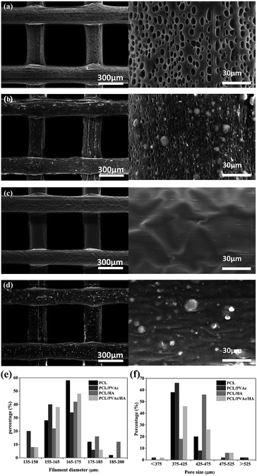
SEM micrographs (left side) and higher magnification images (right side) of PCL (a), PCL/PVAc (b), PCL/HA (c), and PCL/PVAc/HA (d) scaffolds are shown in Fig. 2a–d. The printed porous structure and the filament featured a homogeneous and controlled structure as precise as the 3D designed shape. The PCL stent contained many micropores on the filament surface with a diameter of less than 10 μm (Fig. 2a). The PCL/PVAc stent looked smooth with the exception of a small corrugation on the surface (Fig. 2b). On the filament surface, the PCL/HA stent contained both the micropores (less than 5 μm in size) and many white convex apophyses caused by the addition of HA microparticles (Fig. 2c). The PCL/PVAc/HA stent (Fig. 2d) also contained many HA microparticles and appeared rougher than the PCL/PVAc stent. By contrast, the surfaces of PCL/HA and PCL/PVAc/HA scaffolds were rougher compared to those of PCL and PCL/PVAc, where many HA microparticles were observed on the filament surfaces.
The filament diameter and the hole size (formed by a filament gap) of the scaffolds are shown in Fig. 2e and f. For the four groups, the filament diameters of scaffolds were mainly in the range of 155–175 μm, and the major hole size was in the range of 375–425 μm. Only the hole size of PCL/HA group was in the 425–475 μm range. The hole sizes of all groups were lower than the setting parameter of 500 μm, which has been set by the computer as the controlling parameter.
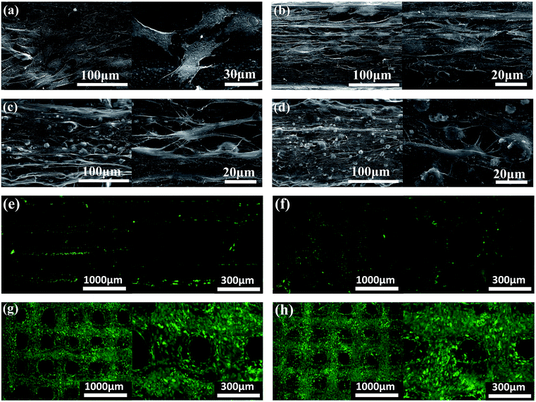
The morphology and distribution of the BMSCs seeded on PCL, PCL/PVAc, PCL/HA and PCL/PVAc/HA scaffolds at day 14 are presented by SEM and microscopic fluorescent images in Fig. 3a–d. The cells attached well, spread on all scaffolds to form a cell layer, and showed normal polygonal morphology with abundant interlinked filopodia. Some cells also wrapped the HA microparticles on PCL/HA (Fig. 3c) and PCL/PVAc/HA (Fig. 3d). A sharp contrast in fluorescent stained images in Fig. 3e–h has been observed, which implies that more living cells are expressed on PCL/HA (g) and PCL/PVAc/HA (h) scaffolds at day 14. The Cellstain-Calcein-AM stained cells grew not only on the scaffold surface but also in the holes of the scaffolds.
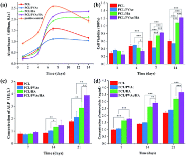
Cell proliferation was evaluated using CCK8 assay. Bezier curves, fitted according to the absorbance and the corresponding histogram with differences, are shown in Fig. 4a and b. From day 1 to day 7, the cells in all groups proliferated continuously. At day 4, the cell viability on the PCL/PVAc/HA scaffold seemed the weakest of all three groups (p < 0.001 compared to PCL and PCL/PVAc groups, p < 0.01 compared to PCL/HA group). However, on day 7 and day 14, the PCL/PVAc/HA groups showed the highest values of all groups in both cell viability and concentration of ALP and OC (p < 0.001 or p < 0.01). Later, the groups containing HA were significantly superior to the other two groups without HA in cell proliferation and differentiation (p < 0.001 or p < 0.01). Even among the groups containing, the PCL/PVAc/HA group possessed the obvious advantage over PCL/HA group on day 7 and day 14 (p < 0.001). There is no statistically significant difference between the PCL scaffold and the PCL/PVAc scaffold.
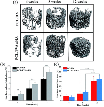
Because the PCL/HA and PCL/PVAc/HA scaffolds exhibited higher cell proliferation and osteogenic activity, the two scaffolds were selected for implantation into the femoral condyle defects of New Zealand rabbits for 4, 8 and 12 weeks. The new bone morphology and volume in the scaffolds at different implantation periods, obtained via reconstruction and quantitative analysis of micro-CT, are shown in Fig. 5. The bone images in Fig. 5a indicated that new bone tissue gradually grew with the implantation time, first on the periphery then in the holes of the scaffolds. More new bone formation in the PCL/PVAc/HA scaffold can be seen in Fig. 5b. The new bone volume was obviously larger than that of the PCL/HA scaffold after 8 weeks (p < 0.001).
The H&E stained histological sections of the harvested scaffold samples at 4, 8 and 12 weeks have shown an increasing growth of the new bone with time (Fig. 6), first on the periphery then in the holes of scaffolds, confirming the results of micro-CT results. At 4 weeks, both the PCL/HA scaffold and PCL/PVAc/HA scaffold were wrapped by the new bone tissue. At 8 weeks, some new bone tissue appeared in the holes of the scaffolds. At 12 weeks, there was more bone tissue in the scaffold porous structure, and the PCL/PVAc/HA scaffold exhibited higher bone formation (24.48 ± 3.02%) compared to that of the PCL/HA scaffold (18.42 ± 0.66%). The specific ratio of new bone to the total bone defect area has been calculated for these sections, which have shown significant growth from 8 weeks (p < 0.001) to 12 weeks (p < 0.001) (Fig. 5c).
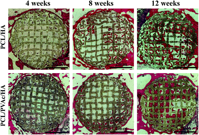 | ||
| Fig. 6 H&E stained histological section images of PCL/HA and PCL/PVAc/HA scaffolds after implantation in bone defects for 4, 8 and 12 weeks. | ||
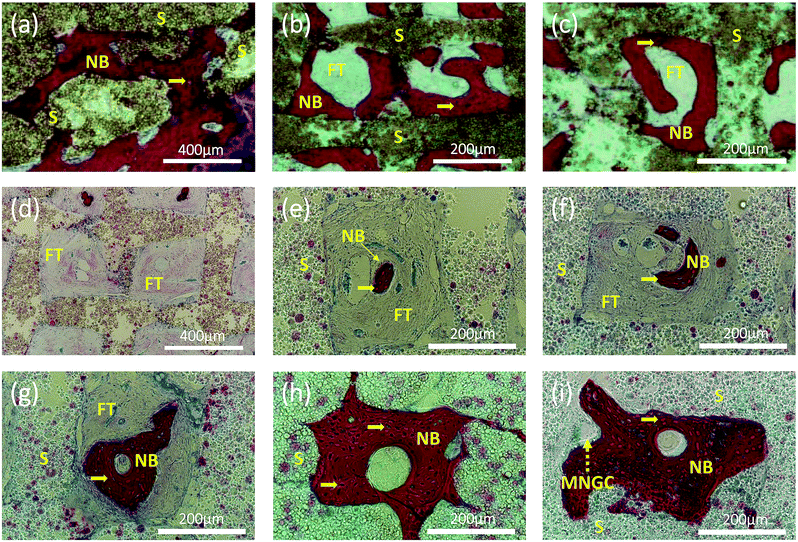
Interestingly, at higher magnification, we can observe two types of new bone formation patterns in the scaffold grids (Fig. 7). One pattern represents the new bone formed directly on the grid matrix (a–c). The other represents the new bone which grew first in the grid centre then filled the holes of the scaffolds (Fig. 7d–i), forming a structure similar to osteon. A multinucleated giant cell (yellow dashed arrow) appears at the edge of the new bone in Fig. 7i.
Discussion
The objective of this study was to develop a specific material system for 3D printing scaffolds suitable for bone repair and reconstruction. The 3D printing technique has the advantage of preparing scaffolds according to the design or clinical individual requirements of various shapes, material composition and interconnective porous structure.5,10 The material selection for bone scaffolds is crucial and difficult because of the dual requirement for printing feasibility and biological tissue repair. In the study, PCL was chosen as the major component of scaffolds because of its favorable characteristics in 3D printing, such as mechanical strength and biocompatibility.31–33 The slow degradability of PCL is also a merit to maintain the scaffold strength in vivo, which could meet the need of gradual reconstruction of new tissue. However, the hydrophobic surface of PCL matrix is not good for cells adhesion and proliferation. So, we choose PVAc as the versatile component of the scaffold. There are three reasons for the addition of PVAc to the scaffold matrix. Firstly, the hydrophilic PVAc could improve the hydrophilicity of PCL matrix to promote the attachment of proteins and cells. Secondly, the low melting point of PVAc could help the scaffold molding at an appropriate temperature close to that required in clinical applications. Finally, the fast-degradation of PVAc could improve the exposure of bioactive HA particles compared to that of PCL, promoting biological activity of cells. Both the improvement of hydrophilicity and degradation of the material system for printing scaffolds will be beneficial to bone regeneration and reconstruction.34–37The results indicate that the PVAc component reduced the mechanical strength of scaffolds and made the scaffold softer than a pure PCL scaffold. The reinforcement of HA particles on the mechanical properties of PCL/HA and PCL/PVAc/HA scaffolds was also obvious. The filament diameter and hole size of all scaffolds decreased in different degrees compared to the set nozzle diameter and filament gap. Thus, the dimensional deviation caused a shrinkage of scaffold structure in contrast to the designed shape. Due to evaporation of the solvent, the shrinkage of the printed scaffold structure occurred during the deformation and solidification procedure after inks were extruded.14 Additionally, in contrast to PCL/PVAc and PCL/PVAc/HA scaffolds, the PCL/HA scaffold displayed minimum shrinkage, because inorganic particles exhibited low deformation during the printing and setting process. Although the compressive strength and modulus of the tri-component PCL/PAVc/HA scaffold are lower than those of PCL and PCL/HA scaffolds, the values are still in the middle of the range of mechanical properties of human cancellous bone (compressive strength is 0.8–11 MPa and modulus is 12–140 MPa).38 So the strength of the PCL/PAVc/HA scaffold is enough to provide mechanical support of a porous host site. Besides, the hole size, interconnective porous structure and porosity of the PCL/PAVc/HA scaffold are also suitable for cell adhesion and ingrowth, and new bone formation, as demonstrated by in vitro cell culture and in vivo animal experiments. Compared to other three scaffolds, the tri-component PCL/PAVc/HA scaffold showed better cell proliferation and significant increase of ALP and OC activity. In addition, the in vivo bone formation of the tri-component scaffold is also superior to that of the PCL/HA scaffold. These exciting results could be attributed to the synergistic effect or collaborative contribution of the PAVc component and HA component.
The enzyme alkaline phosphatase (ALP) is an indicator of osteoblastic activity, which plays a role in the formation of bone minerals and shows the commitment of stem cells to the osteoblastic phenotype, while the osteocalcin (OC) is mainly produced by osteoblasts as a sign of osteoblastic transformation. Higher expression of ALP and OC on the PCL/PAVc/HA scaffold in vitro illustrates that the mixing of PAVc and HA in PCL scaffold is successful, and this may also be the reason of better osteogenesis of the tri-component scaffold in vivo. A suitable selection of materials is crucial for both 3D printing and biological activity.39,40
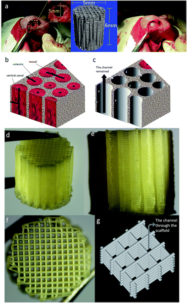
As expected, the 3D printed porous structure of scaffolds is well organized and very regular. The space formatted by the connection of the holes of all layers looks like a quadrate channel. So, the printed scaffold, which we would like call “channel structure”, guides bone reconstruction through the channels or induces bone tissue growth in the direction of design. The micro-CT images and the histological images show that there was more new bone tissue in the PCL/PVAc/HA scaffold than in the PCL/HA scaffold, and more concentric bone structure could be observed in the holes of the PCL/PVAc/HA scaffold. Even at 12 weeks, the scaffold structure was still maintained due to the slow degradability of PCL matrix. When the reconstruction of bone tissue was finally realized after a 12 week implantation, the PCL matrix slowly degraded in vivo and its degradation products were not harmful to the body.22 The 3D printed PCL/PVAc/HA scaffold can be considered a controlled degradable bone biomaterial for repair of complex structural defects, based on its tri-component composition system and regular channel structure.
In the H&E stained tissue sections, we observed two types of new bone formation patterns in the scaffold grids or channels. One pattern is similar to normal CaP porous scaffolds that new bone formed directly on or contacting the matrix;15 the other new pattern we found is the new bone tissue formed first in the center of the grid and then arranged in concentric circles. The latter pattern is analogous to the osteogenesis pattern formation of osteon or Haversian canals of cortical bone. This concentric circular structure or the new bone formation pattern has not been observed in other 3D-printed scaffolds or reported previously.14
As we know, osteons are the basic units of cortical bone. The osteon-like concentric bone structure in the channels of the PCL/PVAc/HA scaffold should be useful for the repair of the long cortical bone which is still difficult to achieve with traditional bone scaffolds.41–44 In long bones, endochondral ossification remains the most important mechanism of bone formation.45 In this context, there are two possible factors resulting in an interesting biological phenomenon. One major factor is the degradation of PVAc.46 Chemical modification of a scaffold surface is the most commonly used strategy to modulate cell function via incorporation of cell-adhesion ligands, such as RGD peptide sequence.47 However, restoration of a wounded tissue is a complex multistep physiological process that starts with proteolytic degradation of the surrounding matrix. The faster degradability of PVAc component via its hydrolysis may expose more HA particles on the surface of the PCL/PVAc/HA scaffold. The calcium component of HA may trigger Ca2+-dependent endopeptidases via a cysteine-switch mechanism, resulting in cell adhesion and strong biological stimulation of osteocytes,48 which could deliver bone morphogenetic protein-2 to introduce the osteocytes aggregation and differentiation in the scaffolds.49 Material degradation resulted in an unstable surface of the PCL/PVAc/HA scaffold, where the osteocytes were difficult to reach. So, the osteocytes proliferated and differentiated from the center of scaffold channel after a 4 week implantation. A multinucleated giant cell appeared at the edge of new bone for further bone remolding. Another major factor may be the channel structure. The inter-connective channel structure of scaffolds is well suited for the transport of nutrients and oxygen and export of metabolic waste.50 The synergistic effect of the two factors stimulated the osteon-like bone formation in the PCL/PVAc/HA scaffold. In the following study, the degradability of the tri-component scaffold and the influence of its metabolic products on osteocytes will be investigated in depth from biochemistry and cytokine aspects.
Conclusion
In summary, four groups of scaffolds, combining different components of PCL, PVAc and HA, have been produced using 3D printing method. After the addition of HA and PVAc components to the PCL matrix, the tri-component PCL/PVAc/HA scaffold showed more favorable characteristics during in vitro cell culture experiment and in vivo bone formation, which can be attributed to the synergistic effect or collaborative contribution of the PAVc component and HA component, as well as the presence of interconnective channel in the porous structure. The new 3D printed scaffold presents a promising prospect for future biomedical applications.Conflicts of interest
The authors declare there is no conflicts of interest regarding the publication of this paper.Acknowledgements
This work was supported by National Key Research and Development Program of China (2016YFA0201703/2016YFA0201700) and the China NSFC project (No. 31670965).Notes and references
- L. Polo-Corrales, M. Latorre-Esteves and J. E. Ramirez-Vick, J. Nanosci. Nanotechnol., 2014, 14, 15–56 CrossRef CAS PubMed.
- A. Oryan, S. Alidadi, A. Moshiri and N. Maffulli, J. Orthop. Surg. Res., 2014, 9, 18 CrossRef PubMed.
- J. U. Lind, T. A. Busbee, A. D. Valentine, F. S. Pasqualini, H. Yuan, M. Yadid, S. J. Park, A. Kotikian, A. P. Nesmith, P. H. Campbell, J. J. Vlassak, J. A. Lewis and K. K. Parker, Nat. Mater., 2017, 16, 303–308 CrossRef CAS PubMed.
- X. Wang, M. Jiang, Z. W. Zhou, J. H. Gou and D. Hui, Composites, Part B, 2017, 110, 442–458 CrossRef CAS.
- Q. Yao, B. Wei, Y. Guo, C. Jin, X. Du, C. Yan, J. Yan, W. Hu, Y. Xu, Z. Zhou, Y. Wang and L. Wang, J. Mater. Sci.: Mater. Med., 2015, 26, 5360 Search PubMed.
- I. Sousa, A. Mendes, R. F. Pereira and P. J. Bártolo, Mater. Lett., 2014, 134, 263–267 CrossRef CAS.
- M. P. Olmedilla, M. Lebourg, J. E. Ivirico, I. Nebot, N. G. Giralt, G. G. Ferrer, J. Soria and J. G. Ribelles, J. Biomater. Appl., 2012, 27, 299–309 CrossRef PubMed.
- J. L. Davila, M. S. Freitas, P. I. Neto, Z. C. Silveira, J. V. L. Silva and M. A. d'Avila, J. Appl. Polym. Sci., 2016, 133, 43031 CrossRef.
- S. Samavedi, A. R. Whittington and A. S. Goldstein, Acta Biomater., 2013, 9, 8037–8045 CrossRef CAS PubMed.
- J. Suwanprateeb, F. Thammarakcharoen and N. Hobang, J. Mater. Sci.: Mater. Med., 2016, 27, 171 CrossRef PubMed.
- H. Seyednejad, D. Gawlitta, R. V. Kuiper, A. de Bruin, C. F. van Nostrum, T. Vermonden, W. J. Dhert and W. E. Hennink, Biomaterials, 2012, 33, 4309–4318 CrossRef CAS PubMed.
- S. Buyuksungur, T. Endogan Tanir, A. Buyuksungur, E. I. Bektas, G. Torun Kose, D. Yucel, T. Beyzadeoglu, E. Cetinkaya, C. Yenigun, E. Tonuk, V. Hasirci and N. Hasirci, Biomater. Sci., 2017, 5, 2144–2158 RSC.
- J. Goole and K. Amighi, Int. J. Pharm., 2016, 499, 376–394 CrossRef PubMed.
- S. Bose, S. Vahabzadeh and A. Bandyopadhyay, Mater. Today, 2013, 16, 496–504 CrossRef CAS.
- H. Wang, Y. Li, Y. Zuo, J. Li, S. Ma and L. Cheng, Biomaterials, 2007, 28, 3338–3348 CrossRef CAS PubMed.
- C. X. F. Lam, M. M. Savalani, S.-H. Teoh and D. W. Hutmacher, Biomed. Mater., 2008, 3, 034108 CrossRef PubMed.
- C. X. F. Lam, D. W. Hutmacher, J.-T. Schantz, M. A. Woodruff and S. H. Teoh, J. Biomed. Mater. Res., Part A, 2009, 90, 906 CrossRef PubMed.
- S. Chattopadhyay, G. Sivalingam and G. Madras, Polym. Degrad. Stab., 2003, 80, 477–483 CrossRef CAS.
- F. Cappitelli and C. Sorlini, Appl. Environ. Microbiol., 2008, 74, 564–569 CrossRef CAS PubMed.
- Q. H. Hu, H. T. Zhu, Z. W. Liu, K. L. Chen, K. F. Tang and C. Qiu, J. Gastroenterol. Hepatol., 2013, 28, 621 Search PubMed.
- L. Ji, W. Wang, D. Jin, S. Zhou and X. Song, Mater. Sci. Eng., C, 2015, 46, 1–9 CrossRef CAS PubMed.
- R. M. Felfel, L. Poocza, M. Gimeno-Fabra, T. Milde, G. Hildebrand, I. Ahmed, C. Scotchford, V. Sottile, D. M. Grant and K. Liefeith, Biomed. Mater., 2016, 11, 015011 CrossRef CAS PubMed.
- G. Zhao, A. L. Raines, M. Wieland, Z. Schwartz and B. D. Boyan, Biomaterials, 2007, 28, 2821–2829 CrossRef CAS PubMed.
- W. Wang, G. Caetano, W. S. Ambler, J. J. Blaker, M. A. Frade, P. Mandal, C. Diver and P. Bartolo, Materials, 2016, 9, 992 CrossRef PubMed.
- B. G. Zhang, J. F. Li, B. Q. Yu, Z. G. Zhu, B. Y. Liu and M. Yan, Oncol. Rep., 2012, 27, 1019–1026 CrossRef CAS PubMed.
- P. S. P. Poh, D. W. Hutmacher, B. M. Holzapfel, A. K. Solanki, M. M. Stevens and M. A. Woodruff, Acta Biomater., 2016, 30, 319–333 CrossRef CAS PubMed.
- W. Chen, J. Liu, N. Manuchehrabadi, M. D. Weir, Z. Zhu and H. H. Xu, Biomaterials, 2013, 34, 9917–9925 CrossRef CAS PubMed.
- L. E. Sidney, G. R. Kirkham and L. D. Buttery, Stem Cells Dev., 2014, 23, 605–617 CrossRef CAS PubMed.
- W. Hatakeyama, M. Taira, N. Chosa, H. Kihara, A. Ishisaki and H. Kondo, Int. J. Mol. Med., 2013, 32, 1255–1261 CrossRef CAS PubMed.
- J. Li, M. Chen, X. Wei, Y. Hao and J. Wang, Materials, 2017, 10, 831 CrossRef PubMed.
- M. A. Woodruff and D. W. Hutmacher, Prog. Polym. Sci., 2010, 35, 1217–1256 CrossRef CAS.
- X. Luo, D. Barbieri, R. Duan, H. Yuan and J. D. Bruijn, Acta Biomater., 2015, 26, 331–337 CrossRef CAS PubMed.
- S. J. Lee, D. Lee, T. R. Yoon, H. K. Kim, H. H. Jo, J. S. Park, J. H. Lee, W. D. Kim, I. K. Kwon and S. A. Park, Acta Biomater., 2016, 40, 182–191 CrossRef CAS PubMed.
- G. Sivalingam, S. Chattopadhyay and G. Madras, Chem. Eng. Sci., 2003, 58, 2911–2919 CrossRef CAS.
- G. Sivalingam, R. Karthik and G. Madras, Polym. Degrad. Stab., 2004, 84, 345–351 CrossRef CAS.
- G. Sivalingam and G. Madras, Chem. Eng. Sci., 2004, 59, 1577–1587 CrossRef CAS.
- L. Pastorino, F. Pioli, M. Zilli, A. Converti and C. Nicolini, Enzyme Microb. Technol., 2004, 35, 321–326 CrossRef CAS.
- T. E. Orr, P. A. Villars, S. L. Mitchell, H. P. Hsu and M. Spector, Biomaterials, 2001, 22, 1953–1959 CrossRef CAS PubMed.
- A. Melocchi, F. Parietti, A. Maroni, A. Foppoli, A. Gazzaniga and L. Zema, Int. J. Pharm., 2016, 509, 255–263 CrossRef CAS PubMed.
- Y. Hu, H. C. Gao, Z. S. Du, Y. X. Liu, Y. Yang and C. Y. Wang, J. Mater. Chem. B, 2015, 3, 3848–3857 RSC.
- X. Shan and D. Hu, Exp. Ther. Med., 2017, 14, 5007–5011 CAS.
- A. Oryan, S. Monazzah and A. Bigham-Sadegh, Biomed. Environ. Sci., 2015, 28, 57–71 CAS.
- D. R. Trotta, C. Gorny Jr, J. C. Zielak, C. C. Gonzaga, A. F. Giovanini and T. M. Deliberador, J. Craniomaxillofac. Surg., 2014, 42, 738–743 CrossRef PubMed.
- R. Marsell and T. A. Einhorn, Injury, 2011, 42, 551–555 CrossRef PubMed.
- G. Karsenty, Nature, 2003, 423, 316–318 CrossRef CAS PubMed.
- G. Sivalingam and G. Madras, Chem. Eng. Sci., 2004, 59, 1577–1587 CrossRef CAS.
- V. P. Shastri, Adv. Mater., 2009, 21, 3246–3254 CrossRef CAS PubMed.
- J. Gross and C. M. Lapiere, Proc. Natl. Acad. Sci. U. S. A., 1962, 48, 1014–1022 CrossRef CAS.
- A. M. Henslee, P. P. Spicer, D. M. Yoon, M. B. Nair, V. V. Meretoja, K. E. Witherel, J. A. Jansen, A. G. Mikos and F. K. Kasper, Acta Biomater., 2011, 7, 3627–3637 CrossRef CAS PubMed.
- H. N. Chia and B. M. Wu, J. Biol. Eng., 2015, 9, 4 CrossRef PubMed.
| This journal is © The Royal Society of Chemistry 2019 |

