
 Open Access Article
 This Open Access Article is licensed under a Creative Commons Attribution-Non Commercial 3.0 Unported Licence
Culturing and patch clamping of Jurkat T cells and neurons on Al2O3 coated nanowire arrays of altered morphology†
Jann Harbertsa,
Robert Zierolda,
Cornelius Fendlera,
Aune Koitmäea,
Parisa Bayata,
Irene Fernandez-Cuestaa,
Gabriele Loersb,
Björn-Philipp Diercksc,
Ralf Fliegertc,
Andreas H. Gusec,
Carsten Ronningd,
Gaute Otnesef,
Magnus Borgströmef and
Robert H. Blick *ag
*ag
aCenter for Hybrid Nanostructures, Universität Hamburg, Luruper Chaussee 149, 22761 Hamburg, Germany. E-mail: rblick@chyn.uni-hamburg.de; Tel: +49 40 42838 1975
bCenter for Molecular Neurobiology Hamburg, University Medical Center Hamburg-Eppendorf, Falkenried 94, 20251 Hamburg, Germany
cDepartment of Biochemistry and Molecular Cell Biology, The Calcium Signaling Group, University Medical Center Hamburg-Eppendorf, Martinistraße 52, 20251 Hamburg, Germany
dInstitute for Solid State Physics, Friedrich-Schiller-University Jena, Helmholtzweg 3-5, 07743 Jena, Germany
eNanoLund, Lund University, Box 118, 22100 Lund, Sweden
fSolid State Physics, Lund University, Box 118, 22100 Lund, Sweden
gMaterial Science and Engineering, College of Engineering, University of Wisconsin-Madison, Madison, Wisconsin 53706, USA
First published on 9th April 2019
Abstract
Nanowire substrates play an increasingly important role for cell cultures as an approach for hybrid bio-semiconductor junctions. We investigate Jurkat T cells and neurons from mice cultured on Al2O3 coated ordered and randomly distributed nanowires. Cell viability was examined by life/membrane staining reporting comparable viability on planar and nanowire substrates. Imaging the hybrid interface reveals a wrapping of the cell membrane around the very nanowire tip. Patch clamp recordings show similar electrophysiological responses on each type of nanowires compared to planar control substrates. We demonstrate that the morphological characteristic of the nanowire substrate plays a subordinate role which opens up the arena for a large range of nanowire substrates in a functionalized application such as stimulation or sensing.
1 Introduction
Chemical and physical properties of surfaces and culture substrates have a significant influence on adhesion and viability of seeded dissociated cells.1–4 Hence, nano- and micro-structured substrates lately gained increasing attention in cell biology.5 Vertically aligned nanowires (NWs) as culturing substrate play here an important role, since variations in length, diameter, and density of the NWs influence cellular growth parameters, viability, and adhesion.6–9 Furthermore, NW substrates can be used to support directed polarization of cells, e.g. outgrowth of axons from neurons,10 to measure mechanical cell properties,11 or to constrain cellular movement and spreading.12,13 Note, compared to planar substrates, functional NWs can interact on a nanoscopic level with the cell and the cell's membrane. Such local stimulation and interactions which cannot be realized by planar substrates allow for novel applications such as in optogenetics, as light guiding or emitting components,14–16 for electrical sensing17–19 as well as indirect photo current stimulation once p–n junctions are integrated,20,21 to name a few of them. Of course, in a first step one has to prove that the cell's viability and electrophysiology are not drastically altered on NW samples compared to planar reference substrates.Typically, cellular outgrowth and guiding experiments are analyzed with fluorescent labeling techniques as well as light microscopy primarily delivering a visual impression.22,23 For functional measurements of cell characteristics, such as membrane capacitance, gating properties of ion channels or amplitudes of neural action potentials, to name a few of them, a more precise method—patch clamping—is required.24–26 However, conventional inverted patch clamp setups are limited to transparent substrates and thus are not suitable for opaque semiconductor samples. Hence, a custom-built upright patch clamp setup with a long working distance objective was used in this study, which is compatible with the types of samples used herein as illustrated in Fig. 1a. The substrates consisted of ordered arrays of indium phosphide (InP) NWs with identical lengths as well as randomly distributed zinc oxide (ZnO) NWs with varying heights (cf. Fig. 1b and c). To quantify and compare the regularity and disarrangement of the NW substrates we calculated corresponding fast Fourier transforms (FFTs) of the top view SEM images. The results are shown in Fig. 1d and e. The bright spots mark the reciprocal lattice proving high accuracy of the repeating structure of the ordered NW substrate. On the contrary, absence of bright spots in the reciprocal image prove no repeating structures of the random NW substrate. In order to avoid any influence of the substrate's materials onto the outgrowth behavior and to study only on the geometry's impact, all substrates have been covered with a thin layer of aluminum oxide (Al2O3) by atomic layer deposition (ALD). A small pitch between individual NWs of less than 500 nm results for both types of samples in a high NW density. Standard Petri dishes and planar Al2O3 have been used as control growth substrates. We employed human T lymphocytes (Jurkat cells) and cerebellar granule cells from mice (neurons) for our studies. Considering the developed model for NW/cell interaction depending on NW density, length, and diameter in Buch-Månson et al.,27 we expect the cells to stay on top of the NW tips, due to the high NW density. Comparable studies which combine NW arrays and patch clamping were performed with restricted areas of NWs and low NW densities.28,29 In these configurations, the cells either adhered predominantly on areas without NWs or were wrapping around the entire NW. In our configuration, where just the NW tips carry the cells, the physical pressure of the pipette tip against the cell membrane during giga seal formation must be considered. Therefore, this undertaking also addresses the question whether spiky NW substrates are suitable for patch clamping applications without significantly damaging the cell. Our results can confirm this and show proper cell viability of both Jurkat cells and neurons independent of the NW arrangement and height distribution.
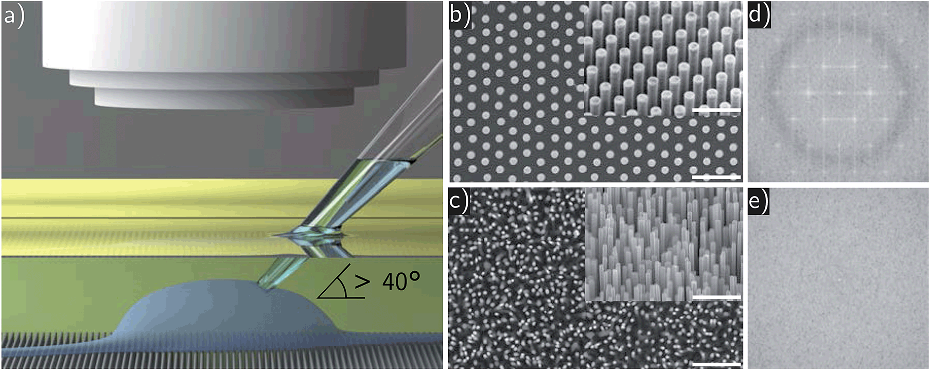 | ||
| Fig. 1 (a) Scheme of the upright patch clamp configuration. A non-immersion objective with extra long working distance is used. The neuron is settled on top of the NW substrate while the patch clamp pipette approaches with an angle of more than 40° between pipette and substrate. (b) A scanning electron microscope (SEM) image of the ordered pristine InP NWs: the NWs are aligned in a defined array with a pitch of 500 nm. The diameter is 180 nm with a length of 2 μm. Scale bar: 2 μm. (c) A SEM image of randomly distributed as-prepared ZnO NWs on silicon substrate. The diameters are between 70 and 180 nm, the length is about 3 μm, the average pitch is about 300 nm. Scale bar: 2 μm. Insets: angle of 40°, scale bars: 1 μm. (d) A FFT of the SEM image of ordered NWs. The bright spots mark the reciprocal lattice proving high accuracy of the repeating structure of the ordered NW substrate. (e) A FFT of the SEM image of random NWs. Absence of bright spots in the reciprocal image prove no repeating structures of the random NW substrate. | ||
2 Methods
2.1 Nanowire preparation
The arrayed and randomly arranged NWs consisted of InP and ZnO, respectively. For the sake of comparability both types of NWs and a planar control were covered with a thin layer of biocompatible Al2O3 (10–15 nm) deposited via ALD.30 Note, for ZnO, the aluminum oxide also serves as passivation layer which is required due to chemical instability of ZnO at pH 7.4 of the cell culture medium.The InP NWs were fabricated in an epitaxial growth process with gold droplets as seeds arranged in an array on InP(111)B substrates via nanoimprint lithography.31 The nanoimprint technique facilitates control of the NW diameter through the seed particle size, and the regular and uniform seed particle array supports the achievement of identical NW lengths during the growth process. Here, we used a NW diameter of 180 nm, a length of 2 μm, and a pitch of 500 nm. The gold tip was removed by wet etching in a two times cycled procedure using iodine–potassium iodide solution and diluted phosphoric acid, respectively. The ZnO NWs were grown self-catalytic, self-assembled, and epitaxial on a 500 nm ZnO layer on top of silicon substrates. This process results into disordered arrays with NWs of a few micrometer length (with slight varying distribution) and diameters between 70 and 180 nm.32 ALD was performed in a custom-built reactor utilizing trimethyl aluminum and water as precursors both kept at room temperature with a constant purge gas flow of about 25 sccm. In a typical ALD process pulse, exposure, and pump time was for both precursors 0.05 s, 30 s, and 90 s, respectively.
2.2 Cell culture
The Jurkat cells were cultured in Gibco RPMI 1640 + GlutaMAX™-I medium with 25 mM 4-(2-hydroxyethyl)-1-piperazineethanesulfonic acid (HEPES), 7.5% new-born calf serum (NCS) and 1.2% (w/v) penicillin/streptomycin in T75 cell culture flasks at 37 °C and 5% CO2 in air. The cell suspension was diluted with fresh medium every 2–3 days to keep the cell concentration between 0.3 × 10⁶ and 1.2 × 10⁶ cells per ml.The neurons – postnatal cerebellar neurons – were derived from 6–7 days old wild-type mice (strain C57Bl6) of either sex or mice expressing GFP under the direction of the human ubiqutin C promoter (C57BL/6-Tg(UBC-GFP)30Scha/J) and were isolated as described in Loers et al.33 Cell concentrations of about 2 × 10⁵ cells per ml were used. The culture medium consisted of Neurobasal™ A, penicillin/streptomycin, bovine serum albumin, insulin, L-thyroxine, transferrin holo, sodium selenite, B-27™ supplement (see Loers et al.33 for details) and 8% fetal bovine serum (Capricorn scientific, FBS Advanced). The neurons were cultured at 37 °C and 5% CO2 in air.
2.3 Sample preparation and cellular outgrowth
Control and NW measurements were performed in 35 mm Petri dishes (Fisher Scientific, Biolite). The plain bottom of the Petri dish was used in the control measurements. The NW substrates were sterilized in 70% ethanol and placed into the Petri dish. All substrates were coated with poly-D-lysine (PDL, mol wt 30![[thin space (1/6-em)]](https://www.rsc.org/images/entities/char_2009.gif) 000–70000, 0.1 mg ml−1) in order to support cell adhesion. The coating was performed by covering the substrates with PDL for 30 min at room temperature. Subsequently, the PDL solution was removed and the samples were rinsed with deionized water and air-dried. Samples with Jurkat cells were prepared immediately prior to the measurements as described below. A droplet of cell suspension (20–30 μl) was applied to the substrate and the cells were left to adhere for 15 min in the incubator. Subsequently, the patch clamp bath solution was added. Samples for the neuron cultures were additionally coated with laminin. Here, the substrates were coated with laminin (1–2 mg ml−1) for 20 min in the incubator. Subsequently, the laminin was removed and a droplet of cell suspension (20–30 μl) was applied to the substrate without drying of the remaining laminin. After an incubation period of 45–60 min at 37 °C and 5% CO2 additional growth medium (3 ml) was added. The neurons were cultured 6–7 days in vitro (DIV) before the measurements. The culturing medium was renewed by two-thirds every 2–3 days with fresh medium. For imaging purposes by SEM and FIB, the samples were dried in air after a stepwise ethanol exchange.
000–70000, 0.1 mg ml−1) in order to support cell adhesion. The coating was performed by covering the substrates with PDL for 30 min at room temperature. Subsequently, the PDL solution was removed and the samples were rinsed with deionized water and air-dried. Samples with Jurkat cells were prepared immediately prior to the measurements as described below. A droplet of cell suspension (20–30 μl) was applied to the substrate and the cells were left to adhere for 15 min in the incubator. Subsequently, the patch clamp bath solution was added. Samples for the neuron cultures were additionally coated with laminin. Here, the substrates were coated with laminin (1–2 mg ml−1) for 20 min in the incubator. Subsequently, the laminin was removed and a droplet of cell suspension (20–30 μl) was applied to the substrate without drying of the remaining laminin. After an incubation period of 45–60 min at 37 °C and 5% CO2 additional growth medium (3 ml) was added. The neurons were cultured 6–7 days in vitro (DIV) before the measurements. The culturing medium was renewed by two-thirds every 2–3 days with fresh medium. For imaging purposes by SEM and FIB, the samples were dried in air after a stepwise ethanol exchange.
2.4 Cell viability staining
The cell viability was tested via fluorescent staining and confocal microscopy. Cell somas were dyed with a cell viability indicator (Thermofisher, 496 nm/515 nm ex/em) and cell membranes were dyed with a cell membrane stain (Thermofisher, 555 nm/565 nm ex/em). Imaging was performed with a Leica TCS SP8 confocal microscope equipped with two lasers of 488 nm and 552 nm wavelength, respectively. Cell viability of the Jurkat cells was tested at the same day of transfer to the substrate and cell viability of the neurons was examined after 6 DIV of outgrowth. For staining, the growth medium was exchanged by a 1× dye mixture in Dulbecco's Phosphate-Buffered Saline (DPBS) and the cells were placed for 15 min at 37 °C and 5% CO2 in the incubator. Subsequently, the staining solution was exchanged with a 1× background suppression dye (Thermofisher) in DPBS. With every type of substrate, 4 different areas for Jurkat cells and 6 areas for neurons were analyzed with ImageJ using the cell counter plugin.352.5 Patch clamp setup
Since the substrates for the cells were opaque, an upright patch clamp setup was utilized. In such a configuration, free space above the sample is limited generally. For this reason, the challenge was to achieve a perpendicular contact angle between the micropipette and the cell membrane, which is required for reliable giga seal forming.36 To provide sufficient space, we used a non-immersion objective with an extra long working distance of 11 mm (Nikon CFI TU Plan EPI ELWD 50× N.A. 0.60/W.D. 11.00 mm) installed to a Nikon Eclipse FN1 upright microscope. As sketched in Fig. 1a, the angle between pipette and substrate was at least 40°, so the patch pipette approached the cell membrane in a perpendicular angle yielding high success rates for establishing giga seals. The pipette was mounted to a HEKA red star headstage and the signals were amplified with a HEKA EPC 10 USB patch clamp amplifier. The data was processed with a Bessel low-pass filter at 2.9 kHz. During patch clamping a particularly small amount of bath solution was required to minimize the surface bending of the fluid which downgrades the clear view on the sample. The probe stage carries standard 35 mm Petri dishes and a transfer of the sample was not required for any measurements. All measurements presented were performed with identically fabricated micropipettes. The borosilicate glass capillary blanks (GB150T-8P, Science Products) were pulled with a Sutter Instrument P-2000 pipette puller and subsequently heat polished (CPM-2, ALA Scientific Instruments). The diameter of the pipette tip was about 950 nm, which resulted in tip resistances of 3–5 MΩ and 7–9 MΩ depending on the different patch clamp solutions for Jurkat cells and neurons, respectively.2.6 Electrophysiology
Different compositions of the pipette and bath solution were used for the Jurkat cells and the neurons. The patch clamp solutions for the Jurkat cells were adapted from Partida-Sanchez et al.37 The pipette solution consisted of (in mM) 140KCl, 2MgCl2, 1CaCl2 and 2.5ethylene glycol tetraacetic acid (EGTA) and is buffered with 10 mM 4-(2-hydroxyethyl)-1-piperazineethanesulfonic acid (HEPES). The pH was adjusted to 7.3 with KOH. The bath solution consisted of (in mM) 140NaCl, 5KCl, 2MgCl2, 2CaCl2, 5glucose and was buffered with 10HEPES, adjusted to pH 7.4 with NaOH. The patch clamp solutions utilized for the neurons were provided from Gall et al.38 The pipette solution contained (in mM) 126K gluconate, 0.05CaCl2, 0.15BAPTA, 4NaCl, 1MgSO4, 15glucose, 5HEPES, 3MgATP, and 0.1GTP, pH adjusted to 7.2 with KOH. The bath solution was predicated on artificial cerebrospinal fluid and consisted of (in mM) 120NaCl, 2KCl, 2CaCl2, 1.19MgSO4, 26NaHCO3, 1.18KH2PO4 and 11glucose, equilibrated with carbogen gas (95% O2, 5% CO2) to pH 7.4. All measurements were performed at room temperature. For neurons, the measurements were delayed for a few minutes after establishing the whole-cell mode to let the MgATP and GTP diffuse into the cell interior.3 Results and discussion
We successfully cultured Jurkat cells and neurons on both ordered and randomly arranged NW arrays. After transfer and outgrowth, the cells were examined in terms of viability, interaction with the NWs and conservation of electrophysiological properties. Here, we compared the results with a twofold control on commonly used Petri dishes and additionally on planar Al2O3 coated substrates, because Al2O3 was also used to passivate the NWs.Cell viability was tested by fluorescent life/membrane staining. For Jurkat cells, we observed high cell viabilities apparently independent of the substrate between 98.9 ± 0.8% and 99.6 ± 0.5%, as shown in Fig. 2a. The high viability can be explained by the short time period between cell transfer and measurement and a high viability of cancer cells in general. Exemplary images of stained Jurkat cells on ordered and random NWs are shown in Fig. 2b and c, respectively. Overview images of cells on all four substrates including examples of dead Jurkat cells can be found in Fig. S1 in the ESI.† For neurons, shown in Fig. 2c, we observed cell viabilities of 73.9 ± 3.6% and 72.9 ± 6.2% on the control substrates and 65.4 ± 4.5% and 66.5 ± 4.4% on the NW substrates. The viability is comparable to the literature published in Loers et al.33 and Koitmäe et al.39 The decrease in total viability on NWs can be explained by a more challenging morphology of the substrate. Nevertheless, ordered and random NWs show similar results. Furthermore, exemplary images of stained neurons cultured on both types of NWs are shown in Fig. 2d and e as well as on the control substrates in Fig. S2.† Beside of vital cells, one can also observe the growth of numerous neurites on top all substrate types indicating the successful formation of a complex neural network. Corresponding top view images prepared by SEM are attached in the ESI as Fig. S3 and S4.†
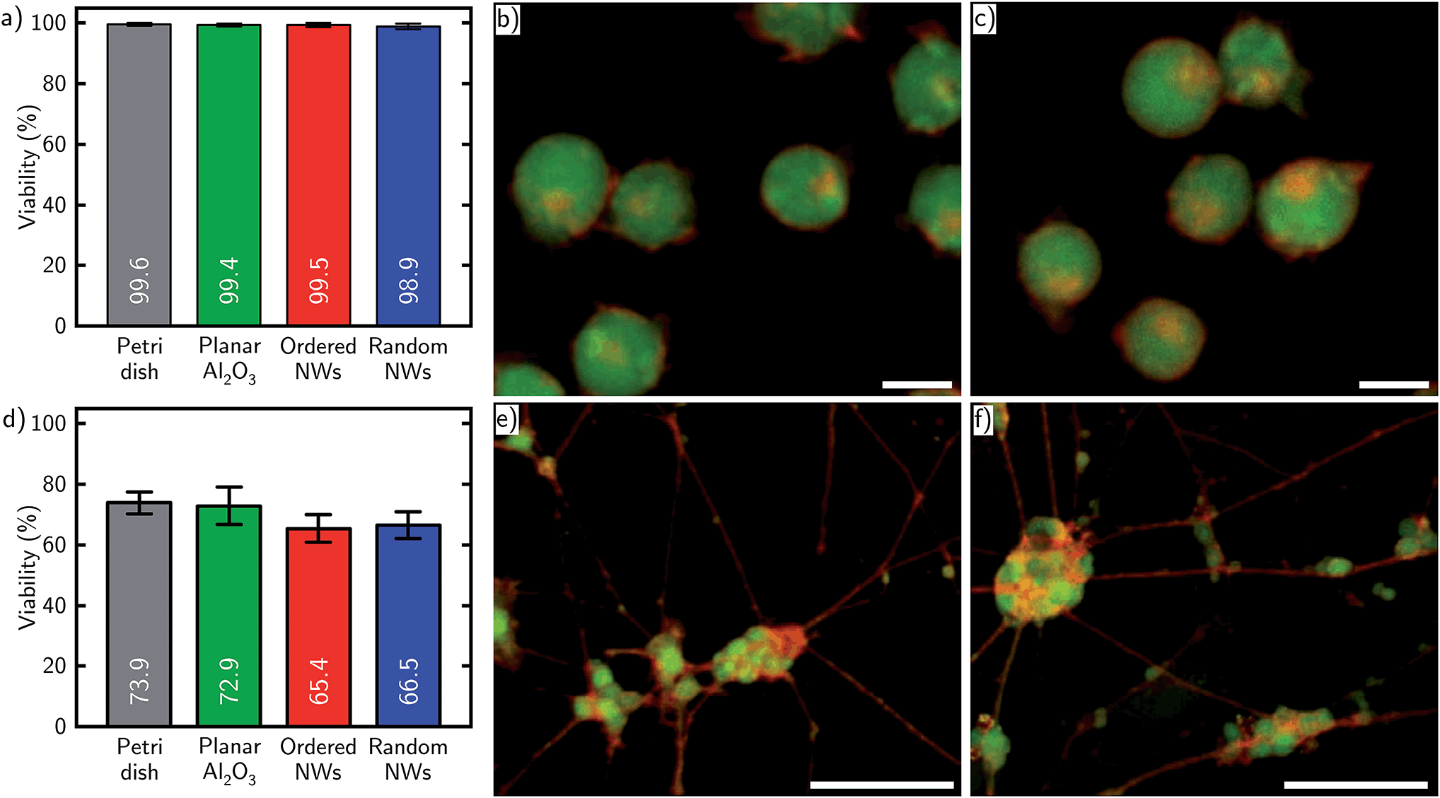 | ||
| Fig. 2 Life/membrane staining results for Jurkat cells and neurons. (a) Bar chart of Jurkat cell viability settled on each substrate. (b) and (c) show stained Jurkat cells cultured on ordered and random NWs. Scale bars: 10 μm. Corresponding images on control substrates can be found in Fig. S1.† (d) Bar chart of neuron viability on each substrate. (e) and (f) show stained neurons including neurites cultured on ordered and random NWs. Scale bars: 50 μm. Corresponding images on control substrates can be found in Fig. S2.† | ||
In a next step, the hybrid interface between NW and cell membrane was examined by focused ion beam (FIB) (Zeiss Crossbeam 550) and SEM. Milling material with the ion beam provided insight to the interface in form of a cross section. Here, particular attention was paid to the contact area between the NW tip and the cell membrane. The compilation of the cross sections for Jurkat cells and neurons on ordered and random NWs, respectively, is shown in Fig. 3a–d. As expected from the model for NW/cell interaction mentioned in the introduction,27 the cells stayed on the NW tips due to the high NW growth density. In particular, Fig. 3a and b illustrate the settling of Jurkat cells on each NW substrate. The insets display a close-up of the NWs and state a slight wrapping of the cell membrane around the very tip of the NW. It appears, that different diameter and arrangement of the NWs tested herein have no decisive influence on the settlement of the Jurkat cells. Similar observations can be made regarding the neuronal cells in Fig. 3c and d. Again, the neurons stay on top of the NWs and show a slight wrapping of the NW tip.
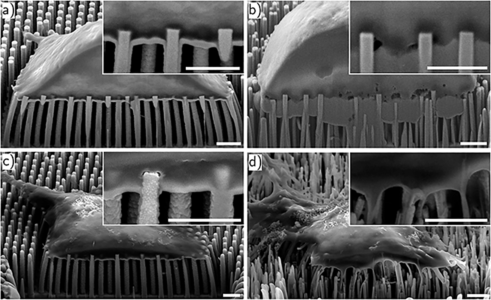 | ||
| Fig. 3 SEM images of Jurkat cells on ordered (a) and randomly distributed (b) NWs as well as neurons on ordered (c) and random (d) NWs. All substrates are covered with a 10–15 nm thick layer of Al2O3. The cross sections were prepared via FIB. In all configurations, the cells stay on top of the NWs. Scale bars: 1 μm. | ||
Furthermore, Fig. 3c and d also specify the statement from before regarding the growth of a neural network on top of the substrate—here: the very NW tip. Note, in both images the neurite in the top left corner of the image remains on top of the NW tips as well. Taking the confocal and SEM images into account, we want to point out that despite the “chaotic” appearance of the randomly distributed NWs, we do not observe any apparent influence of the substrate on the neurons for the ability to form neural networks.
Finally, we examined the cells on all substrates via the patch clamping technique. In order to assess the electrophysiological properties of the cells, we determined the resting membrane potential (Vrest), the membrane capacitance (Cmem), and the membrane time constant (tmem). In these experiments, the membrane capacitance was directly exported by the HEKA Patchmaster software. The required data to specify the remaining parameters were obtained in a three-phased current-clamp measurement. The first section with zero current applied provided the resting potential. The second section injected a small current to the cell in order to shift the membrane potential followed by a third phase which adjusted the applied current to zero again. The exponential decay of the membrane potential toward the resting potential after zeroing the current was then characterized by the membrane time constant. For each substrate—Petri dish, planar Al2O3, ordered and randomly ordered NWs—five different cells were measured. The characteristic electrophysiological factors for Jurkat cells adhered to each type of substrate are summarized in Table 1. Contemplating the measured mean values of each parameter, the resting membrane potentials range from (−53.4 ± 2.9) mV to (−56.6 ± 8.9) mV, the membrane capacitance is between (8.0 ± 1.7) pF and (10.6 ± 2.5) pF, and the time constants range from (11.4 ± 4.0) ms to (12.6 ± 4.1) ms. One can observe that the values of each parameter appear to be in the same range independent on the substrate. In order to support the intuitive interpretation, a Welch's t-test was performed for every data pair to test for statistically significant deviation. No significant deviations occurred within a 95% confidence interval (CI). All calculated t-values are listed in Table S1.† Furthermore, the experimental results are in accordance with the literature.40–42 Analogously, we proceeded with the patch clamp results from the neurons cultured on each type of substrate which are summarized in Table 2. Reviewing the minimally and maximally measured means, the resting membrane potentials range from (−55.9 ± 7.2) mV to (−58.1 ± 4.9) mV, the membrane capacitance is between (3.7 ± 1.0) pF and (4.7 ± 0.8) pF and the time constants range from (9.1 ± 2.9) ms to (15.4 ± 7.3) ms. Repeatedly, the results seem to imply no severe influence of the substrates morphology. We performed a Welch's t-test with every data pair using a 95% CI again. The t-test results for the neurons are noted in Table S2† and show no significant deviations of the electrophysiological properties between each type of substrate. Besides, the determined values are also applicable to ones in the literature.38,43,44
| Petri dish | Planar Al2O3 | Ordered NWs | Random NWs | |
|---|---|---|---|---|
| a Number of cells patched on each type of substrate: n = 5. | ||||
| Vrest (mV) | −56.4 ± 4.6 | −55.9 ± 6.2 | −56.6 ± 8.9 | −53.4 ± 2.9 |
| Cmem (pF) | 10.6 ± 2.5 | 8.1 ± 1.0 | 8.4 ± 1.5 | 8.0 ± 1.7 |
| tmem (ms) | 12.6 ± 4.1 | 11.4 ± 4.0 | 11.9 ± 6.4 | 11.5 ± 5.4 |
| Petri dish | Planar Al2O3 | Ordered NWs | Random NWs | |
|---|---|---|---|---|
| a Number of cells patched on each type of substrate: n = 5. | ||||
| Vrest (mV) | −58.1 ± 4.9 | −55.9 ± 7.2 | −55.9 ± 5.7 | −56.8 ± 6.8 |
| Cmem (pF) | 4.3 ± 0.7 | 4.7 ± 0.8 | 3.7 ± 0.8 | 3.7 ± 1.0 |
| tmem (ms) | 9.1 ± 2.9 | 9.5 ± 7.9 | 11.9 ± 3.5 | 15.4 ± 7.3 |
In addition to the characteristic electrophysiological parameters, we investigated cell specific ion channel activity/response for both cell types. For Jurkat cells, we studied the gating of voltage-gated potassium ion channels in voltage-clamp mode. As a result, the NW substrates have no influence on the voltage–current characteristics compared to both planar control substrates as shown in Fig. 4a. Here, voltage ramps from (−60 to +10) mV with a slope of 80 mV/100 ms were applied to the Jurkat cells while the ionic current through the cell's membrane was measured. At a membrane potential of approximately −30 mV an increased slope of the ionic current is observable. Such a gating at this voltage is also reported in literature and can be assigned to voltage-gated potassium channels in Jurkat cells.45
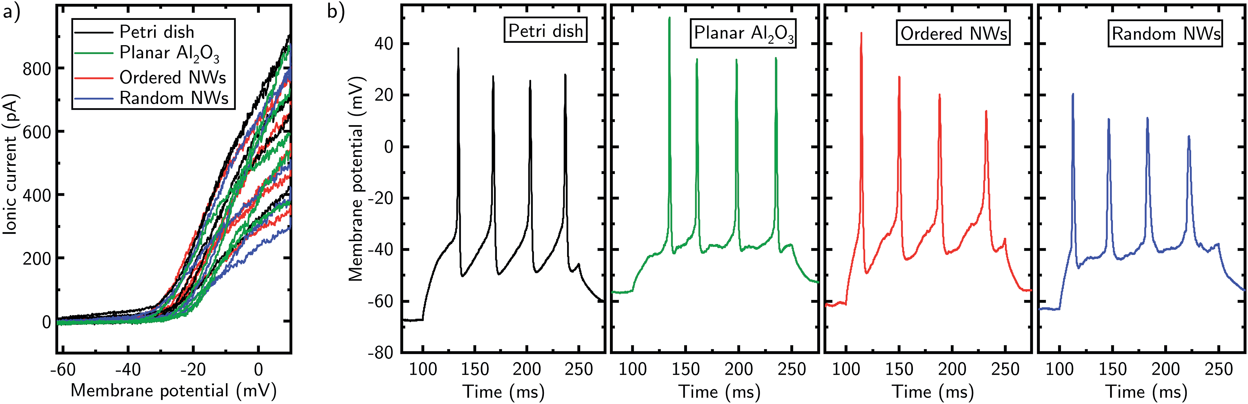 | ||
| Fig. 4 (a) Voltage–current correlation for Jurkat cells in a Petri dish (black), on planar Al2O3 (green), ordered (red) and random (blue) NW substrates. A voltage ramp of −60 mV to +10 mV with a slope of 80 mV/100 ms was applied to the cell. The increase of the slope of the measured current at −30 mV indicates the activation of voltage-gated ion channels. Number of cells measured on each type of substrate: n = 5. (b) Measurements of action potentials of neurons cultured in a Petri dish (black), on planar Al2O3 (green), ordered (red) and random (blue) NW substrates. The stimulation current was injected after 100 ms with a duration of 150 ms. Several actions potentials were fired. | ||
In case of the neurons, we tested for firing of action potentials. As a part of the nervous system, the capability of a neuron to fire action potentials is an important indicator of the ability to process neuronal information and hence states proper cell function. Independently of the culturing substrate, the neurons show characteristic action potentials (cf. Fig. 4b) with amplitudes between 45 mV and 85 mV and a firing rate of 27 Hz, which is in accordance with literature.43,46 During the experiment, a stimulus current was applied in current-clamp mode to the cell with a duration of 150 ms in order to depolarize it above the critical threshold of triggering action potentials.
4 Summary and conclusion
In summary, we cultured cells, specifically human T lymphocytes and cerebellar granule cells from mice, on a Petri dish, planar Al2O3, and Al2O3 surface-passivated ordered and randomly distributed NW substrates and show patch clamp recordings of normal electrophysiological cell activity with a custom-built upright patch clamp setup. SEM images of the NW/cell membrane interface showed that the cells investigated herein are only in contact with the NW tip. This observation is in direct contrast to any other comparable publications where patch clamp recordings have been performed, since the entire NW was wrapped by the cell's membrane due to a low NW growth density.28,29 We showed via patch clamp recordings, that the electrophysiological properties in this configuration were conserved and fundamental cellular responses of both cell types remained intact asserting physical pressure during establishing the giga seal on spiky substrates. In detail, whilst taking into account the results from the electrophysiological characterization of the cells, the proper voltage-gating of the Jurkat cells and firing of action potentials of the neurons, we can state that the nanostructured one-dimensional NW substrate geometry in our study has no detrimental influence on the electrophysiological properties of the cell – when the cell is resting on the NW tips – compared to control experiments on planar substrates and the integrity of the cellular system is conserved. Note, our patch clamp measurements are complementary to live/dead staining analyses as well as to previous studies9,10,47 and reveal the great potential for future investigations on the interaction of functional one-dimensional nano-sized objects with the cell membrane, such as NW solar cells, NW electrodes, nanoscaled 1-dimensional probes or nanotubes for drug delivery, to name a few of them.With respect to generality, we believe that characteristic cell properties of Jurkat cells and neurons may remain conserved on NW substrates independent on roughness, arrangement, and diameter of the NWs – with a substrate geometry and morphology similar to that one shown herein. Hence, this observation might pave the way to use a large variety of NW substrates in diverse applications in combination with sensitive electrophysiological patch clamp measurements. Additionally, with the predictable wrapping of the cell's membrane of the very tip of the NW leading to a point-like contact of nanostructure and cell membrane, our setup is an ideal starting point for future experiments with functionalized NWs, such as NW lasers or NW solar cells in optogenetics and sensing/stimulation experiments, respectively.
Conflicts of interest
There are no conflicts to declare.Acknowledgements
The authors would like to thank the following organizations for funding: the Deutsche Forschungsgemeinschaft (DFG) via Center for Ultrafast Imaging (CUI) under the Excellence Program (EXC-1074), the Joachim Herz Stiftung via BioPict, the Federal Ministry of Education and Research (BMBF) via ForLab, the DFG via FOR1616, NanoLund, the Swedish Energy Agency and the Swedish Research Council (2015-03824). R. H. B. likes to thank Meyer Jackson of the University of Wisconsin-Madison for very helpful discussions. Finally, we would like to acknowledge the Zeiss company for support to prepare the FIB cross sections.References
- A. S. Curtis and M. Varde, JNCI, J. Natl. Cancer Inst., 1964, 33, 15–26 CAS.
- A. Harsch, J. Calderon, R. Timmons and G. Gross, J. Neurosci. Methods, 2000, 98, 135–144 CrossRef CAS PubMed.
- Y. H. Kim, N. S. Baek, Y. H. Han, M. A. Chung and S. D. Jung, J. Neurosci. Methods, 2011, 202, 38–44 CrossRef CAS PubMed.
- M. Lampin, R. Warocquier-Clérout, C. Legris, M. Degrange and M. F. Sigot-Luizard, J. Biomed. Mater. Res., 1997, 36, 99–108 CrossRef CAS PubMed.
- D. Ning, B. Duong, G. Thomas, Y. Qiao, L. Ma, Q. Wen and M. Su, Langmuir, 2016, 32, 2718–2723 CrossRef CAS PubMed.
- J. Lee, B. S. Kang, B. Hicks, T. F. Chancellor Jr, B. H. Chu, H.-T. Wang, B. G. Keselowsky, F. Ren and T. P. Lele, Biomaterials, 2008, 29, 3743–3749 CrossRef CAS PubMed.
- Z. Li, R. Yang, M. Yu, F. Bai, C. Li and Z. L. Wang, J. Phys. Chem. C, 2008, 112, 20114–20117 CrossRef CAS.
- W. Hällström, T. Mårtensson, C. Prinz, P. Gustavsson, L. Montelius, L. Samuelson and M. Kanje, Nano Lett., 2007, 7, 2960–2965 CrossRef PubMed.
- G. Piret, M.-T. Perez and C. N. Prinz, Biomaterials, 2013, 34, 875–887 CrossRef CAS PubMed.
- G. Piret, M.-T. Perez and C. N. Prinz, ACS Appl. Mater. Interfaces, 2015, 7, 18944–18948 CrossRef CAS PubMed.
- Z. Li, J. Song, G. Mantini, M.-Y. Lu, H. Fang, C. Falconi, L.-J. Chen and Z. L. Wang, Nano Lett., 2009, 9, 3575–3580 CrossRef CAS PubMed.
- C. N. Prinz, J. Phys.: Condens. Matter, 2015, 27, 233103 CrossRef PubMed.
- S. Qi, C. Yi, S. Ji, C.-C. Fong and M. Yang, ACS Appl. Mater. Interfaces, 2009, 1, 30–34 CrossRef CAS PubMed.
- J. C. Johnson, H. Q. Yan, P. D. Yang and R. J. Saykally, J. Phys. Chem. B, 2003, 107, 8816–8828 CrossRef CAS.
- S. Rühle, L. K. Van Vugt, H. Y. Li, N. A. Keizer, L. Kuipers and D. Vanmaekelbergh, Nano Lett., 2008, 8, 119–123 CrossRef PubMed.
- C. Baratto, R. Kumar, E. Comini, G. Faglia and G. Sberveglieri, Opt. Express, 2015, 23, 18937 CrossRef CAS PubMed.
- K.-Y. Lee, I. Kim, S.-E. Kim, D.-W. Jeong, J.-J. Kim, H. Rhim, J.-P. Ahn, S.-H. Park and H.-J. Choi, Nanoscale Res. Lett., 2014, 9, 56 CrossRef PubMed.
- W. Kim, J. K. Ng, M. E. Kunitake, B. R. Conklin and P. Yang, J. Am. Chem. Soc., 2007, 129, 7228–7229 CrossRef CAS PubMed.
- K.-Y. Lee, S. Shim, I.-S. Kim, H. Oh, S. Kim, J.-P. Ahn, S.-H. Park, H. Rhim and H.-J. Choi, Nanoscale Res. Lett., 2010, 5, 410–415 CrossRef CAS PubMed.
- E. Garnett and P. Yang, J. Am. Chem. Soc., 2008, 130, 9224–9225 CrossRef CAS PubMed.
- J. Wallentin, N. Anttu, D. Asoli, M. Huffman, I. Aberg, M. H. Magnusson, G. Siefer, P. Fuss-Kailuweit, F. Dimroth, B. Witzigmann, H. Q. Xu, L. Samuelson, K. Deppert and M. T. Borgstrom, Science, 2013, 339, 1057–1060 CrossRef CAS PubMed.
- D. J. Stephens, Science, 2003, 300, 82–86 CrossRef CAS PubMed.
- S. A. Galdeen and A. J. North, in Cell Migration, Springer Protocols, 2011, pp. 205–222 Search PubMed.
- E. Neher and B. Sakmann, Nature, 1976, 260, 799–802 CrossRef CAS PubMed.
- E. Neher, B. Sakmann and J. H. Steinbach, Pflügers Arch., 1978, 375, 219–228 CrossRef CAS PubMed.
- B. Sakmann, Annu. Rev. Physiol., 1984, 46, 455–472 CrossRef CAS PubMed.
- N. Buch-Månson, S. Bonde, J. Bolinsson, T. Berthing, J. Nygård and K. L. Martinez, Adv. Funct. Mater., 2015, 25, 3246–3255 CrossRef.
- J. T. Robinson, M. Jorgolli, A. K. Shalek, M.-H. Yoon, R. S. Gertner and H. Park, Nat. Nanotechnol., 2012, 7, 180–184 CrossRef CAS PubMed.
- J. Abbott, T. Ye, L. Qin, M. Jorgolli, R. S. Gertner, D. Ham and H. Park, Nat. Nanotechnol., 2017, 12, 460–466 CrossRef CAS PubMed.
- D. S. Finch, T. Oreskovic, K. Ramadurai, C. F. Herrmann, S. M. George and R. L. Mahajan, J. Biomed. Mater. Res., Part A, 2008, 87, 100–106 CrossRef PubMed.
- G. Otnes, M. Heurlin, M. Graczyk, J. Wallentin, D. Jacobsson, A. Berg, I. Maximov and M. T. Borgström, Nano Res., 2016, 9, 2852–2861 CrossRef CAS.
- C. Borschel, S. Spindler, D. Lerose, A. Bochmann, S. H. Christiansen, S. Nietzsche, M. Oertel and C. Ronning, Nanotechnology, 2011, 22, 185307 CrossRef PubMed.
- G. Loers, S. Chen, M. Grumet and M. Schachner, J. Neurochem., 2005, 92, 1463–1476 CrossRef CAS PubMed.
- C. Kilkenny, W. Browne, I. Cuthill, M. Emerson and D. Altman, J. Pharmacol. Pharmacother., 2010, 1, 94 CrossRef PubMed.
- S. Ebihara, K. Shirato, N. Harata and N. Akaike, J. Physiol., 1995, 484(Pt 1), 77–86 CrossRef CAS.
- A. Molleman, Patch Clamping, John Wiley & Sons, Ltd, Chichester, UK, 2002, pp. 1975–1977 Search PubMed.
- S. Partida-Sanchez, A. Gasser, R. Fliegert, C. C. Siebrands, W. Dammermann, G. Shi, B. J. Mousseau, A. Sumoza-Toledo, H. Bhagat, T. F. Walseth, A. H. Guse and F. E. Lund, J. Immunol., 2007, 179, 7827–7839 CrossRef CAS.
- D. Gall, C. Roussel, I. Susa, E. D'Angelo, P. Rossi, B. Bearzatto, M. C. Galas, D. Blum, S. Schurmans and S. N. Schiffmann, J. Neurosci., 2003, 23, 9320–9327 CrossRef CAS PubMed.
- A. Koitmäe, M. Müller, C. S. Bausch, J. Harberts, W. Hansen, G. Loers and R. H. Blick, Langmuir, 2018, 34, 1528–1534 CrossRef PubMed.
- M. D. Cahalan and K. G. Chandy, Immunol. Rev., 2009, 231, 59–87 CrossRef CAS PubMed.
- P. Ross, S. Garber and M. Cahalan, Biophys. J., 1994, 66, 169–178 CrossRef CAS PubMed.
- G. Dupuis, J. Héroux and M. D. Payet, J. Physiol., 1989, 412, 135–154 CrossRef CAS.
- C. Roussel, T. Erneux, S. N. Schiffmann and D. Gall, Cell Calcium, 2006, 39, 455–466 CrossRef CAS PubMed.
- C. Rössert, S. Solinas, E. D'Angelo, P. Dean and J. Porrill, Front. Cell. Neurosci., 2014, 8, 1–20 Search PubMed.
- T. E. DeCoursey, K. G. Chandy, S. Gupta and M. D. Cahalan, Nature, 1984, 307, 465–468 CrossRef CAS PubMed.
- B. P. Bean, Nat. Rev. Neurosci., 2007, 8, 451–465 CrossRef CAS PubMed.
- G. Piret, E. Galopin, Y. Coffinier, R. Boukherroub, D. Legrand and C. Slomianny, Soft Matter, 2011, 7, 8642 RSC.
Footnote |
| † Electronic supplementary information (ESI) available. See DOI: 10.1039/c8ra05320k |
| This journal is © The Royal Society of Chemistry 2019 |