
Concentration-dependent fabrication of short-peptide-based different self-assembled nanostructures with various morphologies and intracellular delivery property†
Subramaniyam
Sivagnanam
a,
Amutha
Arul
a,
Soumyajit
Ghosh
 a,
Ananta
Dey
bc,
Suvonkar
Ghorai
*d and
Priyadip
Das
*a
a,
Ananta
Dey
bc,
Suvonkar
Ghorai
*d and
Priyadip
Das
*a
aDepartment of Chemistry, SRMIST, SRM Nagar, Potheri, Kattankulathur, Kancheepuram District, Chennai, Tamil Nadu 603203, India. E-mail: priyadipcsmcri@gmail.com; priyadip@srmist.edu.in
bAcademy of Scientific and Innovative Research (AcSIR), Ghaziabad – 201002, India
cCSIR-Central Salt & Marine Chemicals Research Institute, Bhavnagar 364002, India
dDepartment of Biotechnology, SRMIST, SRM Nagar, Potheri, Kattankulathur, Kancheepuram District, Chennai, Tamil Nadu 603203, India
First published on 25th July 2019
Abstract
The fabrication of supramolecular architectures with various morphologies via the self-assembly of appropriate molecular building blocks is a proficient and convenient fabrication approach. Moreover, controlling the key parameters responsible for the self-assembly process is vital for understanding the fundamental aspects of molecular self-assembly, which provide insights into the fabrication of new assemblies with functional nano-architectures. To this end, in the present study, we report the synthesis of a simple tripeptide Boc-Phe-Phe-Glu-(OH)2 (PS1) and the mechanism for the concentration-dependent self-assembly of this tripeptide building block. This peptide self-assembled into discrete spherical assemblies at a low concentration. An increase in concentration of the monomeric building block during self-assembly generated nanotubes by connecting the nanospheres through neck formation. At higher concentration and with a prolonged incubation time, the self-assembly fabricated necklace-like supramolecular architectures comprise both linear and spherical units together. Furthermore, the spherical assemblies produced with a lower concentration of monomeric building blocks were encapsulate small molecules as well as able to release these inside the cells. Therefore, these spherical assemblies represent a potential candidate for the delivery of exogenous entities directly into cells and may behave like conventional sphere-based drug-delivery vehicles. To the best of our knowledge, this is the first report on the fabrication of a biomolecular necklace-like complex assembly with a bi-component type of morphology from a single short peptide-based molecular backbone.
Introduction
Molecular self-assembly is an impulsive/natural process that occurs under thermodynamic and kinetic conditions based on the combination of specific and local molecular interactions to generate various well-ordered structures.1 Recently, biomolecular self-assembly has attracted considerable attention due to its implication for the design and fabrication of supramolecular nanostructures, further leading to the development of advanced materials and scaffolds2 with a wide range of applications in nano-biotechnology, including drug delivery.3 The self-assembly process is controlled by the balance of the interplay of various noncovalent forces, such as hydrogen bonding, hydrophobic interactions, aromatic stacking, and electrostatic interactions.4 Biomolecules have an inherent propensity to self-assemble into different nanostructures with various morphologies.5 In the last few decades, a variety of biomolecules, like DNA, lipids, peptides, and proteins, have been employed for the construction of self-assembled nanostructures for different applications, such as biosensors,6 templates for growth of other functional materials,7 bioimaging,8 tissue engineering,9 enzymatic catalysis,10 gene expression,10a,11 and drug-delivery platforms.12 The self-assembly of biomolecules is dependent on several factors, like the self-assembling building blocks, solvent, concentration, time of incubation, and pH of the solution. There are different reports in the literature where a changeover in self-assembly has been observed by altering the self-assembling building blocks,13 concentration,14 solvent,15 pH,16 chirality,17 temperature,18 and by the introduction of functional groups, such as thiols.19 Among the different biomolecules, peptides are among the most promising building blocks due to their unmatched biocompatibility, chemical diversity, and resemblance to proteins. Inspired from the protein assembly in biological systems, various self-assembled structures have been constructed using several amino acid sequences.20In this context, it is apparent that the morphological identities of the self-assemblies exclusively control their specific applications.21 Therefore, tuning the morphology of the self-assembled structures is highly anticipated, and specifically, the fabrication of multiple nanostructures from a single molecular backbone has become a topic of intense investigations. Among the several key parameters that can control the aggregation process of the monomeric building block during the self-assembly process, concentration plays an important role. Chen and coworkers investigated the concentration as a key factor in directing the aggregation of oligopeptides (EAK16-II) during the self-assembly process and proposed the aggregation mechanism.22 Zhang and coworkers also described how linear surfactant-like oligopeptides with variable glycine tails self-assembled concurrently into nanotubes and vesicles.23 Such peptide nanotubes (PNTs) can be used for intracellular-delivery applications. Recently, Li and coworkers established that simple cationic dipeptides self-assemble into nanotubes (CDPNTs), and upon dilution, these CDPNTs can also rearrange to form vesicles. These CDPNTs are cell membrane penetrable and can be absorbed by the cells upon spontaneous conversion into vesicles and are thus able to deliver oligonucleotides into the interior of cells.14a Herein, we report on simple tripeptides (BOC-Phe-Phe-Glu-(OH)2; see Scheme 1) that self-assembled into nanospheres at physiological pH and with an increasing concentration of building blocks, these nanospheres could rearrange to form nanotubes by connecting the nanospheres through neck formation.24 More importantly, during self-assembly at higher concentration (much higher than the critical aggregation concentration; CAC) with a prolonged incubation time (∼pH 3–4), the tripeptide monomeric building blocks form beaded string-like complex assemblies with decorated molecular necklaces. Meital and coworkers were the first to describe the formation of this type of peptide-based complex supramolecular architecture by the co-assembly of two simple aromatic peptides, phenylalanine and its tert-butyl dicarbonate (Boc) protected analogue, which they termed as “biomolecular necklaces.”25 The structural similarity in terms of the morphological aspects between this necklace-like complex assembly formed by the peptide PS1 and the beaded filaments formed by glycoprotein fibronectin suggests that this bi-component supramolecular architecture may be considered as a new useful biomaterial for biomedical applications. Therefore, we explored the generation of several supramolecular assemblies with morphological variation from a single molecular backbone by tuning the concentration of the building block unit during self-assembly processes. This approach can be adapted by other classes of peptides and may potentially lead to the finding of new peptide-based nanostructures with improved control of their self-assembly process. Furthermore, the nanospheres formed by this ultrashort tripeptide PS1 showed low toxicity, a cell penetrating nature, and the ability to carry and deliver small molecules into the cells. This property to transport small molecules into the interior of cells gives a prominent indication for the further use of these spherical structures as potential gene- and drug-delivery systems.
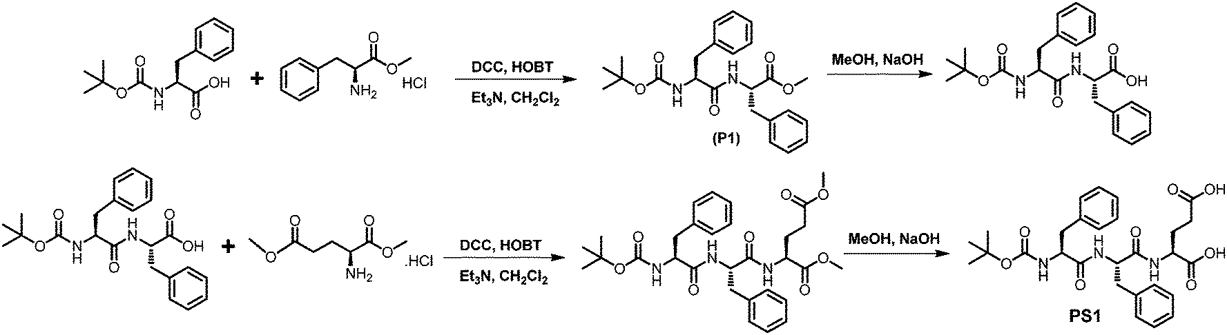 | ||
| Scheme 1 Synthetic methodologies adopted for the synthesis of PS1. | ||
Results and discussion
Tripeptide PS1 was prepared starting from a simple coupling reaction between BOC-phenylalanine and phenylalanine methyl ester to form both N- and C-termini-protected diphenylalanine (P1). First, the C-terminus of P1 was deprotected by ester hydrolysis in methanol followed by another coupling reaction with glutamic acid dimethyl ester. The coupling reaction was performed using DCC and HOBT as coupling reagents and triethylamine (TEA) as the base (Scheme 1; details of the synthetic procedure are provided in the experimental section, ESI†). Compound PS1 was characterized by 1H-NMR (DMSO-d6, 293 K, 500 MHz), 13C-NMR (DMSO-d6, 293 K, 125 MHz) ESI-MS, FT-IR, elemental and XRD analysis (see the ESI†). The absorption and emission spectra of PS1 were recorded at room temperature (Fig. 1A and B). The UV-Vis absorption spectra of PS1 displayed absorption maxima at 211 nm, which could be attributed primarily to a spin-allowed intra-component charge transfer (CT). PS1 exhibited strong emission spectra with two emission maxima at 404 and 429 nm, respectively. The critical aggregation concentration (CAC) for the synthesized peptide PS1 was determined with the use of a tensiometer by measuring the surface tension with a wide range of concentrations (Fig. 1C). Initially, the surface tension dropped down dramatically to a minimum value with increasing concentration, and then it reached a plateau. Above the CAC, the surface tension is extensively independent of the concentration. The CAC from the intersection between the regression straight line of the linearly dependent region and the straight line passing through the plateau was found to be ∼0.65 mg mL−1. The self-assembly propensity of PS1 was then investigated with a wide range of concentrations of the monomeric building block in aqueous alcoholic medium. To trigger the self-assembly process, first, the synthesized peptide PS1 was dissolved in 1,1,1,3,3,3-hexafluoro-2-propanol (HFP) to an initial concentration of 100 mg mL−1. Then, each solution was diluted separately in water to achieve a final desired concentration ranging from 0 to 10 mg mL−1. After incubation for 24 h, the samples were characterized. High-resolution scanning electron microscopy (HR-SEM) analysis revealed that PS1 formed well-ordered spherical structures with nanomeric dimensions within the effective concentration range of 0–2 mg mL−1 (Fig. 1D). Dynamic light scattering (DLS) analysis revealed that the average diameter of these spherical structures was 1020 ± 46 nm (Fig. S10, ESI†). AFM analysis further confirmed the spherical shape of the nanostructures (Fig. 1F). The topography analysis showed that these spherical structures were approximately ∼20–400 nm in height (Fig. S9, ESI†), which were in line with the TEM analysis results (Fig. 1E).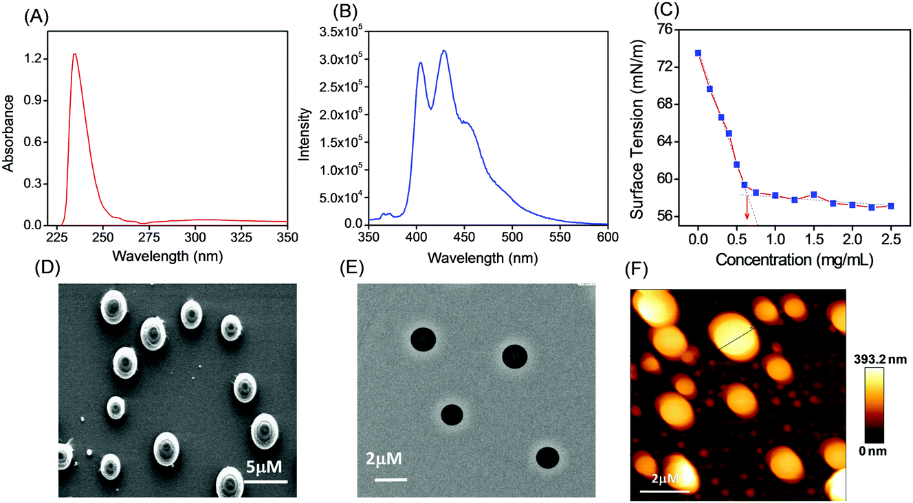 | ||
| Fig. 1 (A) UV-Vis absorption and (B) emission spectra of PS1 (2 × 10⁻⁵ M) in 50% aqueous ethanol medium. (C) Determination of the critical aggregation concentrations (CAC) for PS1 relationship between the surface tension with increasing concentration of PS1. Microscopic analysis of the self-assembled structure formed by PS1: (D) HR-SEM micrographs, (E) TEM micrographs, (F) AFM micrographs (two-dimensional representation). The concentration of the monomeric building used for self-assembly was 1.5 mg mL−1. | ||
With an increase in the effective concentration of the monomeric building block, it was observed that the nanospheres (Fig. 2A and B) were first arranged in an ordered array and then interlinked with each other through neck formation (Fig. 2D and E). Haldar et al. proposed a mechanism for such a structure.24 With a further increase in the effective concentration of the monomeric building blocks during the self-assembly process, we found the existence of two different self-assembled states of this tripeptide PS1: (i) a spherical assembly and (ii) tubular nanostructures, as shown in Fig. 2G and H. We propose that at first, spherical structures arranged in an ordered arrangement and then fused via neck formation. Finally, smoothing of this fused communicated spherical assembly led to structural transformation into nanotubes (Scheme 2). Here, the structural conversion from spherical to tubular structures with increasing concentration can be explained by the driving force responsible for the self-assembly of this tripeptide. In this case, the self-assembly was mainly triggered by two attractive forces: hydrogen bonding and π–π interactions between aromatic moieties.7b,19,26 At a higher concentration of monomeric building blocks, the increased intermolecular nonspecific interactions leads to the system achieving an adequate free energy of association. The presence of aromatic moieties in the peptide backbone consequently promotes a three-dimensional (3D) aromatic-stacking arrangement that acts as an “adhesive” among the hydrogen-bonded spherical units of the peptide PS1 and promotes the formation of nanotubes.7b,19,26 This process of structural transformation is very much similar to that observed for a cationic analogue of the diphenylalanine peptide (OH-Phe-Phe-NH2·HCl).26
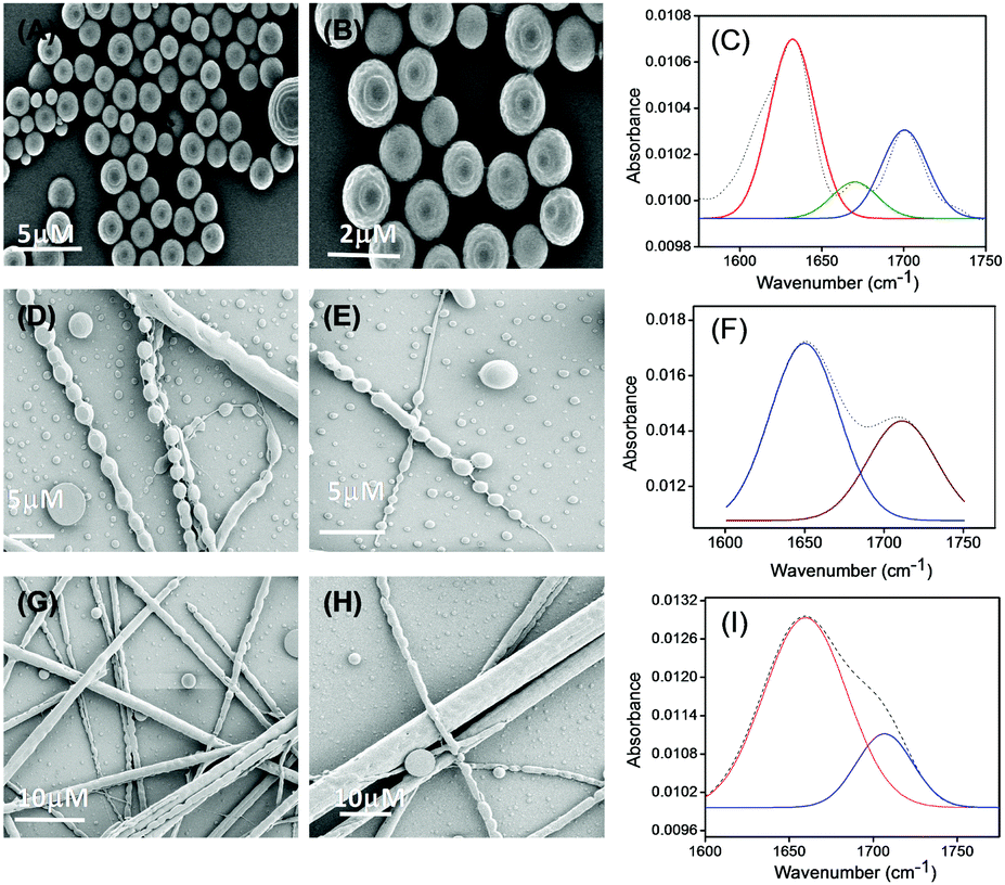 | ||
| Fig. 2 Structural characterization of the self-assemblies formed by PS1 in 50% aqueous ethanol medium using different concentrations of peptide monomer during self-assembly. HR-SEM micrographs of the self-assembled structures formed by PS1; concentration of the monomeric peptide (PS1) is 2 mg mL−1 (A and B), concentration of the monomeric peptide (PS1) is 3–4 mg mL−1 (D and E), concentration of the monomeric peptide (PS1) is 6–9 mg mL−1 (G and H). Deconvoluted FT-IR spectra of the different self-assembled structures formed by PS1 with different morphologies Spherical assemblies (C), connecting spheres (F), nanotubes (I). The dashed line indicates the original FT-IR spectra and the solid line represents the deconvoluted curves with a Gaussian function. | ||
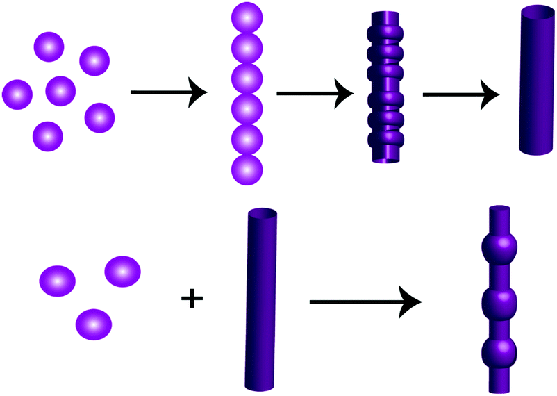 | ||
| Scheme 2 Pictorial representation of the various self-assembled structures with different morphologies formed by the peptide PS1 at different concentrations during self-assembly. | ||
During the course of our self-assembly study, we found that self-assembly of this peptide at higher concentration (9–12 mg mL−1) with a prolonged incubation period of 2–3 days (∼pH = 3 to 4) resulted in the generation of a different complex supramolecular architecture, comprising both tubular and spherical units with completely different morphologies resembling a biomolecular necklace-like structure25 (Fig. 3A and B). Yang and coworkers reported the structural conversion between spherical and tubular structures for a cationic analogue of the diphenylalanine peptide.26 The transition to nanotubes was observed when a solution containing vesicle-like structures was concentrated. In addition, the cationic diphenylalanine analogue also self-assembled into a metastable state sequential joint vesicles-like morphology, which was termed a “necklace-like structure.”27 But the complex structures that we obtained during the course of our study were different from this structure in terms of a morphological aspect. This structure is very much similar to that of the architecture obtained by the co-assembly of two simple aromatic dipeptides: the diphenylalanine and its tert-butyl dicarbonate (Boc)-protected analogue. Each of these peptides can self-assemble into a distinct morphology: diphenylalanine self-assembles into tubular structures and its protected analogue into spherical structures. The morphologies of this type of co-assembled structures are named as “biomolecular necklaces.”25 This supramolecular architecture comprises both linear as well as spherical segments, in which the spherical units are connected through the linear element. This type of structure was generated only when the concentration of the monomeric peptide was moderately high (condition 5, Table 1).
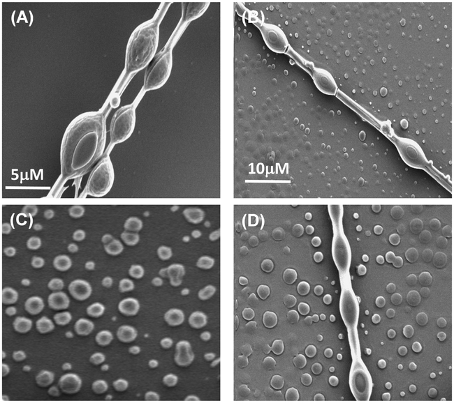 | ||
| Fig. 3 (A and B) HR-SEM micrographs of the “necklace-like” supramolecular assembly formed when the concentration of the monomeric peptide was moderately high (9–12 mg mL−1) with a prolonged incubation period of 2–3 days (∼pH = 3 to 4). (C) HR-SEM analysis of the self-assembled solution having a biomolecular necklace at room temperature heated to 70–80 °C for 10 min, (D) and upon further cooling to room temperature. | ||
| Condition | PS1 (mg mL−1) | pH | Assemblies |
|---|---|---|---|
| 1 | 1–2 | 7.2 | Spheres |
| 2 | 3–4 | 7.2 | Spheres + connecting spheres |
| 3 | 5–6 | 7.2 | Connecting spheres + nanotubes |
| 4 | 6–9 | 7.2 | Nanotubes |
| 5 | 9–12 | 3–4 | Necklace |
In this context, we can propose a mechanism for the formation of this type of bi-component morphology similar to that of the necklace model formation from polyelectrolyte chains.28 Polyelectrolytes are basically charged polymers having ionisable groups. Theoretical and molecular simulation studies showed that charged polyelectrolytes collapse into dense globules.28a These globules undergo a structural conversion into a necklace-like construction of compact beaded strings, where spherical assemblies are connected through a narrow string. This is due to the minimization of the free energy as a result of counter ion condensation on the polyelectrolyte's backbone.
This only happens due to increasing concentration of the salt or polyelectrolytes. Under our above-mentioned experimental conditions (pH 3–4), the tripeptide BOC-Phe-Phe-Glu-(OH)2 bears a net negative charge. This was also confirmed by zeta potential analysis, whereby the zeta potential of the PS1 assembly formed at pH 7.4 was −0.6 mV (Fig. S16, ESI†) and at pH 3.5 was −6.4 mV (Fig. S17, ESI†). Therefore, we can assume that the π–π stacking among the aromatic moieties of the peptide monomer leads to the formation of sequential negative charge, which means it behaves similarly to that of polyelectrolyte chain. On the basis of the polyelectrolyte-based necklace model, we suggest that the increasing concentration of peptide monomer causes the counter ion to condense on the peptide backbone, resulting in a decrease in net charge. As a result, we observed the construction of biomolecular necklace-like structures at a comparatively high concentration of peptide monomer with prolonged incubation for a period of 2–3 days. For further confirmation of our proposed mechanism, we examined the self-assembly process in the presence of salt (NaCl). It would be well expected that the presence of salt will accelerate the necklace formation in the same manner as an increase in peptide or polyelectrolyte concentration.28b,29 We examined the self-assembly of this synthesized tripeptide PS1 at higher concentration (condition 5) in the presence of externally added NaCl, and found that at higher peptide concentration, the presence of NaCl promoted the necklace formation and such self-assembled necklace-like architectures were found to form after 18–24 h incubation instead of the need for a more prolonged incubation time in absence of salt (Fig. S11, ESI†). Furthermore, we also investigated the stability of the biomolecular necklaces. SEM analysis of an aged self-assembled solution having biomolecular necklace-like architectures at room temperature heated to 70–80 °C for 10 min showed the formation of spherical units (Fig. 3C), rather than necklaces. However upon cooling to room temperature, the biomolecular necklaces again re-assembled with moderate yield (Fig. 3D). The formation of a highly ordered supramolecular assembly depends on the effects of several non-covalent interactions as well as on the assembly process conditions.4 Therefore the stability of the self-assembled structures was mainly influenced by the thermodynamic and kinetic factors for the structural assembly, which can also control the process of structural transformation.1c Recently Yan and coworkers reported that a trace amount of water can play a significant role in inducing the self-assembly of a dipeptide to follow the dynamic evolution of peptide self-assembly.30 The thermodynamics of the growth process is mainly governed by a synergistic effect of hydrophobic interactions and hydrogen bonds. A similar type of structural transition was observed between spherical and tubular structures for the cationic analogue of the diphenylalanine peptide (OH-Phe-Phe-NH2·HCl).27 For this peptide, nanotubes were generated when a solution containing vesicle-like structures was concentrated. In addition, this cationic analogue self-assembled into a joined vesicles with a metastable necklace-like structure.27 Unlike the metastable complex structures, this necklace-like structure did not undergo structural evolution, even for a time up to 36 h, thus exhibiting good structural stability. We propose that a combination of different types of non-covalent interactions helped to achieve the thermodynamic stability of this complex self-assembly.30
The above-mentioned results and discussions established the fabrication of multiple functional nanostructures with different morphological identities from a simple single peptide backbone under different self-assembly conditions of various concentrations of building blocks (summarized below in Table 1). More importantly, the morphological alternation could be done by tuning the concentration of the peptide monomer during the self-assembly.
To gain an insight into the secondary conformation of the different self-assembled supramolecular assemblies of PS1 formed at different self-assembly conditions by varying the concentration of monomeric building blocks, we utilized Fourier transform infrared (FT-IR) analysis and deconvoluted each spectrum in the amide I region with a Gaussian function. The FT-IR spectra of the spherical structures formed by PS1 exhibited two major peaks at 1631 and 1698 cm−1, indicating an anti-parallel β-sheet structure,31 and a minor peak at 1670 cm−1, suggesting a β-turn conformation31a,32 (Fig. 2C). The FT-IR spectra of the connecting spheres assemblies formed at relatively higher concentration of PS1 exhibited one major peak at 1650 cm−1 in the amide I region (Fig. 2F), which was ascribed to the considerable disorder or random structure.30,32b,33 The FT-IR spectrum of the nanotube-like structures formed by PS1 exhibited a single peak at 1659 cm−1, which may relate to an α-helix conformation (Fig. 2I).27 Basically, it is well known that small linear peptides comprising 3–6 member amino acids would not exhibit an α-helical conformation due to size restrictions. In this context, we may assume that the supramolecular aggregation of the spherical units in an ordered and organized way through neck formation produce the tubular supramolecular networks, leading to an antiparallel pairing of two monomeric units and resulting in the unanticipated α-helical confirmation due to further aggregation of spherical structures.34
We also investigated the potential application of the spherical structures formed by PS1 at certain concentrations as a delivery platform. We self-assembled PS1 (concentration of the monomeric unit = 1.5 mg mL−1) in the presence of the luminescent dye rhodamine B (RhB). The binding of RhB with the spherical assemblies was carried out during the self-assembly of PS1, leading to RhB-PS1-SA, in which the luminescent dye is incorporated within the spherical structures. The luminescent RhB-incorporated PS1-based spherical assemblies were characterized by microscopy assays using fluorescence microscopy. Fig. 4A and B clearly show the encapsulation or loading of the RhB dye into the PS1-based spherical units. Dynamic light scattering (DLS) analysis revealed that the average diameter of these RhB encapsulated spherical structures was 1030 ± 36 nm (Fig. S14, ESI†), which was very much similar to that of the bare spherical units. The calculated encapsulation efficiency (EE) was 61.56%, while the loading capacity (LC) was 19.7% (see Materials and methods section).
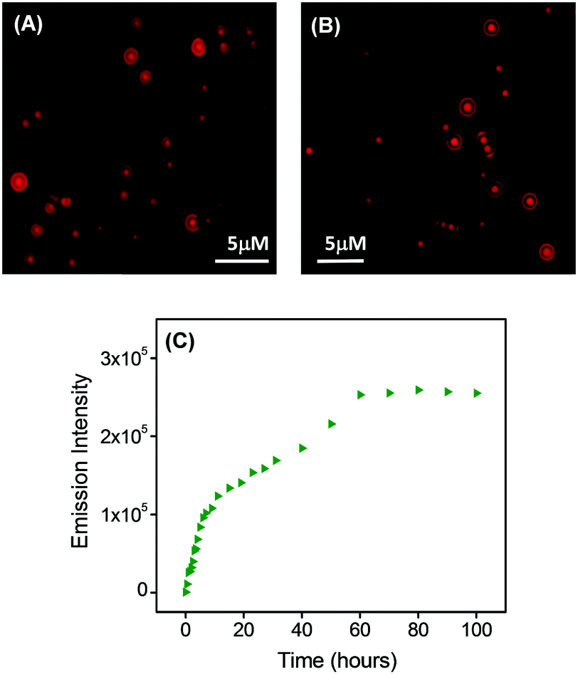 | ||
| Fig. 4 (A and B) Fluorescence microscopic images of rhodamine (RhB)-labeled spherical assemblies generated from PS1 showing spherical structures with high aspect ratios, with the characteristic fluorescence suggesting the presence of RhB across the spherical structures at the microscale. (C) Plot of the measured emission intensity of the PBS buffer solution outside the dialysis bag (containing the RhB-incorporated PS1-based self-assembled spheres; RhB-PS1-SA) with time; λMon = 576 nm, λExt = 542 nm. | ||
The spherical assemblies were kept at 100 °C for 4 h and no significant structural alterations were observed up to 100 °C (Fig. S12, ESI†), thus validating the thermal stability of the spherical structures in solution. We also checked the thermal stability of the tubular structures by keeping them at 80–90 °C for 30 min, which led to the formation of spherical assemblies (Fig. S13, ESI†), However upon cooling to room temperature, the spherical units again re-assemble into tubular structures, thus exhibiting thermal reversibility of the nanotube formation.
The dye release capability of the RhB-incorporated spherical assemblies was then evaluated using steady state fluorescence measurement analysis. RhB-PS1-SA particles were dispersed in PBS buffer and relocated into a dialysis bag (MWCO 3 kDa), in PBS buffer at room temperature. The emission intensity of aliquots were measured at different time intervals for 4 days. This fluorescence measurement experiment exhibited that there was a steady increase in the emission intensity with increasing time (Fig. 4C). This observation clearly revealed that the concentration of the dye in the buffer (outside the dialysis bag) steadily increased with time. This was due to the release of the dye molecules from the dye-incorporated self-assembled nanostructures. Initially the emission intensity was measured after a 30 min time interval, followed by at 1 h, 2 h, 4 h, and after that, by measuring the fluorescence intensity at a time interval of 10 h. It was observed that there was a steady increase in the emission intensity up to 60 h (2.5 days), but after that we did not observe any significant increase in the emission intensity; it was likely that the dye release process was completed and had reached equilibrium at this late point. To confirm this hypothesis, we followed the dialysis system for a longer time (up to 100 h) and observed an insignificant change in the emission intensity. The emission reached a plateau after 70 h (∼3 days) (Fig. 4C).
The eventual cytotoxicity of the spherical assembly generated from PS1 toward the human colorectal cell line, HCT116 was tested by conventional MTT assays.35 Cell proliferation was estimated after 48 h of incubation following a standard protocol (see the ESI†). After 48 h of incubation with nanospheres of PS1, the percentage cell viability was calculated. A statistically considerable cytotoxic effect at 300 μM concentration was found with a decrease in cell viability of approximately 35% (data not shown). This effect was way above the normal physiological range used and no other substantial differences in cell proliferation at concentrations ranging from 1 to 200 μM were observed, indicating the biocompatibility of the compound. The cellular viability was estimated to be >60% after incubation for 48 h at a concentration of ≤200 μM (Fig. 5A).
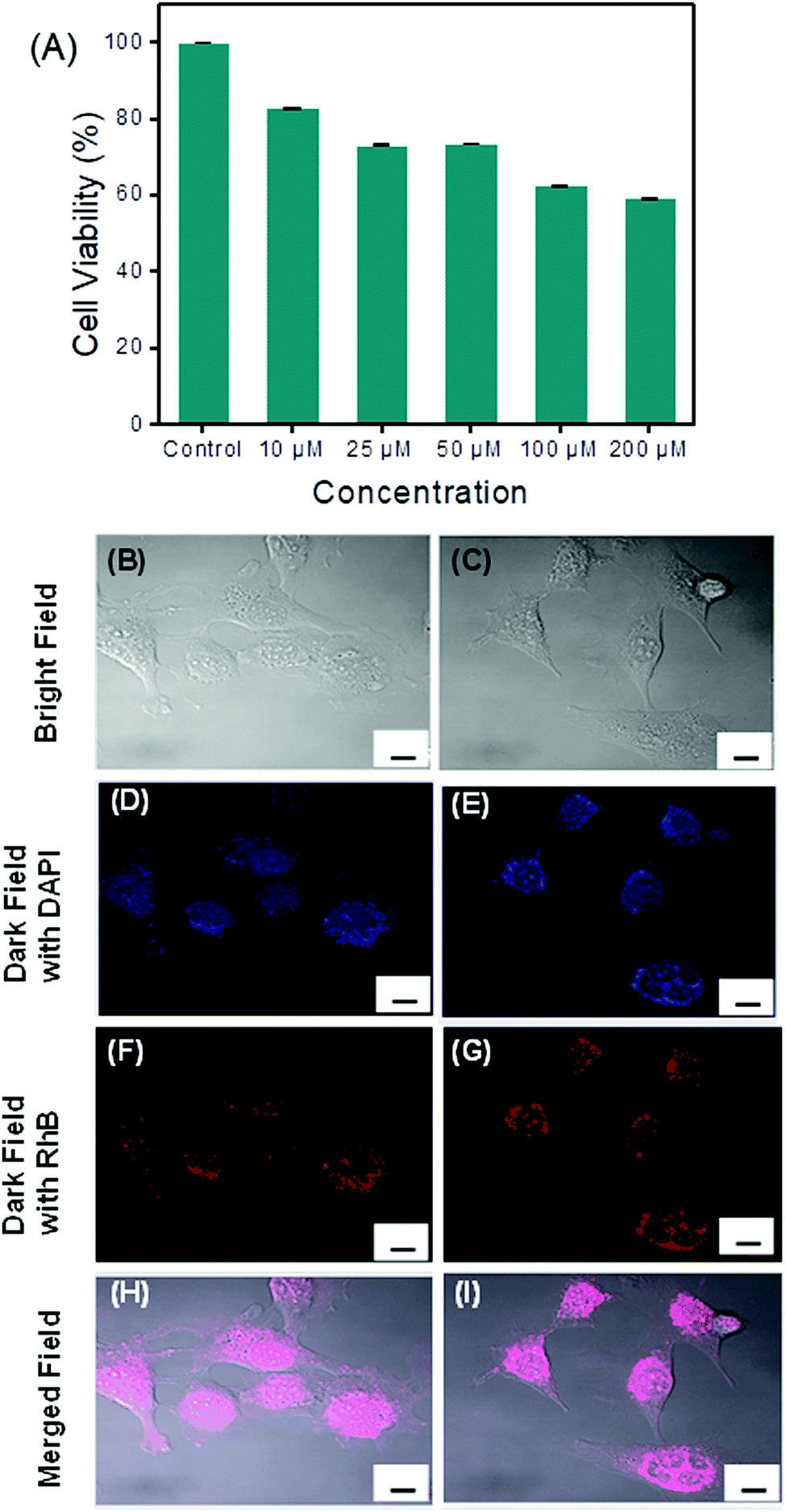 | ||
| Fig. 5 Upper panel: (A) Cell viability values (%) estimated by MTT cell viability test versus the incubation concentration of PS1. HCT116 cells were cultured in the presence of 0–200 μM of PS1 and at 37 °C for 48 h (% viability was calculated considering 100% growth in the absence of PS1). Bottom panel: Confocal laser scanning micrographs of living HCT 116 cells treated for 16 h with RhB-PS1-SA. (B and C) Represent the bright field images of the HCT 116 cell culture. (D and E) Representative dark field image of HCT 116 cell culture nuclei stained with DAPI. (F and G) Representative dark field image of HCT 116 cells treated with RhB-PS1-SA. (H and I) Merged image of DAPI, RhB-PS1-SA and bright field images. Scale bar = 10 μm. | ||
The insignificant cytotoxicity of the PS1-based spherical structures open the possibility for intracellular drug delivery. In this context, we examined the cell diffusion capability of these spherical assemblies. HCT116 cells, representing a stable and well-established human colorectal cancer cell line frequently used for biomedical research applications, were treated in aqueous Tris–HCl buffer solution (pH = 7.2) for 30 min at 37 °C for up to 16 h with 100 μM of a RhB dye-incorporated spherical assembly of PS1 (RhB-PS1-SA). After the incubation, the cells were washed three times with phosphate buffer solution (PBS), followed by staining with DAPI, a well-known nuclear dye. The cells were again washed thoroughly with PBS and fixed with para formaldehyde. The cells were then visualized under a confocal microscope. Confocal microscopy analyses revealed that untreated HCT116 cells did not display any intracellular or intercellular fluorescence (Fig. S15, ESI†). After incubation with the RhB-PS1-SA, the confocal micrographs clearly displayed that RhB-PS1-SA were actively incorporated into the cells and were able to reach the intracellular compartments, as shown in Fig. 5. Cellular internalization in the rhodamine fluorescence channel was nicely visible after 16 h of incubation, a period that possibly allowed a particle's enrichment inside the cells (Fig. 5F and G). On the other hand, a comparatively low level of cellular internalization in the RhB florescence channel (Fig. S15, ESI†) was observed after 2 h of incubation, this is due to the increased concentration of released dye with the increasing time. Moreover, the dye-incorporated nanoparticles were disseminated largely into the intracellular compartments and were able to release the incorporated dye in a controlled manner (Fig. 5F and G), resulting in an intracellular localization of the fluorescence intensities with uneven distribution, as shown by the co-localization between the DAPI and the rhodamine (Fig. 5I and J). This result evidently revealed the intracellular dye release ability of the PS1-based self-assembled nanospheres, marking this spherical assembly as a promising candidate for drug delivery.
Conclusions
In conclusion, we described the synthesis and results from the self-assembly study of ultrashort tripeptide PS1 having the sequence of BOC-Phe-Phe-Glu-(OH)2 with di carboxylic acid groups. This peptide could be fabricated into different supramolecular architectures with various morphologies using different concentrations of monomeric building blocks during self-assembly. At low concentration, mainly the π–π non covalent interaction promoted the formation of spherical assemblies. With an increase in concentration of the peptide monomer, nanotubes were generated by the fusion of connecting spheres through neck formation. Furthermore, self-assembly at a higher concentration of monomeric peptide with a prolonged incubation time of 2–3 days (∼pH = 3–4) fabricated a complex architecture with a necklace-like morphology comprising both linear units (nanotubes) and spherical units. Therefore, we were able to generate assemblies with functional nano-architectures having morphological individualities by altering the concentrations of a single short peptide during the self-assembly process. More importantly, the spherical units were able to encapsulate small molecules and deliver them into cells, thus representing a potential candidate for drug delivery directly into cells. To the best of our knowledge, this is the first report of the development of a bi-component necklace-like supramolecular architecture from a single tripeptide building block via self-assembly. Furthermore, considering the structural similarity with beaded filaments formed by glycoprotein fibronectin, these necklace-like assemblies could be exploitable for future biomedical applications.Experimental section
Materials and methods
All the chemicals and solvents were commercially available and were used as received. Phenylalanine, glutamic acid, N,N′-dicyclohexylcarbodiimide, 1-hydroxy benzotriazole, BOC anhydride, trimethylchlorosilane (TMSCl), and triethyl amine were purchased from Sisco Research Laboratories Pvt. Ltd (SRL, India). Potassium hydrogen sulphate, HCl, sodium chloride, sodium sulfate, sodium hydroxide, and sodium carbonate were purchased from Finar Chemicals Pvt. Ltd (India). 1,1,1,3,3,3-Hexafluoro-2-propanol (HFP) and rhodamine-B dye were purchased from Sigma Aldrich.Self-assembly of PS1
A fresh stock solution of peptide was prepared by dissolving the lyophilized forms of the PS1 in HFP to a concentration of 100 mg mL−1. Then, we blended this peptide solution in several different proportions and diluted them with aqueous ethanol (50%) to get the desired concentrations of the peptide for self-assembly. The polarized solvent allowed the molecules to self-assemble.High-resolution scanning electron microscopy (HR-SEM)
A 10 μL drop of a self-assembled solution of PS1 in different concentrations was placed on a glass cover slip and allowed to dry at RT. The substrates were then coated with gold using a Leica EM ACE 200; 2–3 nm gold coater. SEM analysis was performed using a high-resolution scanning electron microscope (FE-SEM, JEOL JSM-7100F) operating at 18 kV.Transmission electron microscopy (TEM)
A 10 μL drop of a self-assembled solution of PS1 was placed on a 200-mesh copper grid, covered by carbon-stabilized Formvar® film. After 1 min, excess fluid was removed from the grid. The samples were analyzed using a transmission electron microscope, JEOL-JEM-2100 Plue (High resolution scintillator) operating at 200 kV.Atomic force microscopy analysis
Topography images of the spherical structures on glass cover slips were taken using a NT-MDT MOSCOW instrument (model-Ntegra Aura) working in AC mode. Si3N4 cantilever probes with a spring constant of 3 N m−1 and a resonance frequency of 75 kHz were used.Fourier transform infrared spectroscopy (FT-IR)
Fourier transform infrared spectra were recorded using a IR Tracer-100 FT-IR spectrometer (Shimadzu) with a Deuterated Lanthanum α Alanine doped TriGlycine Sulphate (DLaTGS) detector. The peptide self-assembled solutions were deposited on a CaF2 window and dried under vacuum. The peptide deposits were resuspended with D2O and subsequently dried to form thin films. The re-suspension procedure was repeated twice to ensure maximal hydrogen-to-deuterium exchange. The measurements were taken using 4 cm−1 resolutions and an average of 2000 scans. The transmittance minimal values were determined using the Lab solutions IR analysis program (IR Tracer).UV-Vis spectroscopy
UV-Vis absorption spectra of the synthesized peptide in aqueous ethanol solvent system were recorded using a UV/Vis spectrophotometer (Labman, 19002, Double beam UV-Vis absorption spectrometer).Fluorescence spectroscopy
For the optical in vitro dye release assay, fluorescence measurements were performed at RT using a fluorescence spectrometer (Fluorolog, HORIBA). The emission spectra were collected from 550 to 750 nm with an excitation wavelength of 542 nm. Both the excitation and emission slit widths were set to 2.0 nm. The fluorescence intensity at 576 nm was used for the quantitative analysis.Microanalysis
(C, H, N) analysis was performed using a Vario Micro Cube (Elementar) instrument.Dye labeling and dye release of PS1 self-assembled spheres
The incorporation of RhB (rhodamine-B) was conducted during the self-assembly of PS1. RhB at a concentration of 10−1 mol L−1 (dissolved in ethanol and water in a 1![[thin space (1/6-em)]](https://www.rsc.org/images/entities/char_2009.gif) :1 ratio) was added to PS1 (dissolved in HFP at 100 mg mL−1 concentration) with the desired dilution (1.5 mg mL−1; effective concentration). Then the mixture was left for overnight. This mixture underwent spontaneous accommodation of the dye molecule within the PS1-based spherical assembly. Following conjugation, samples were prepared by drop-casting 25 μL of the conjugate mixture on the glass coverslip and dried in air. The remaining solvent was left drying overnight at room temperature under vacuum. Then, the assemblies were washed carefully with ultrapure water several times to eliminate the residual free RhB and then dried properly at room temperature. The luminescent RhB-incorporated PS1-based spherical assemblies were characterized by performing microscopy assays using a fluorescence microscope. The dye-labeled nanospheres was prepared by the above-mentioned protocol and kept for precipitation overnight. The solvent was decanted and the dye-encapsulated spherical assemblies were re-dispersed in PBS (10 mM Nacl pH = 7.4, 150 mM). After that, this suspension (2 mL) was transferred into a dialysis bag (MWCO 3 kDa), and the bag was dipped in 40 mL of PBS at RT. The emission intensity of the buffer solution outside the dialysis bag was measured at different time intervals for 4 days. The volume of the solution was kept constant by adding 1 mL of the original PBS solution after each measurement. The emission intensities were measured at room temperature using a fluorescence spectrophotometer. The emission spectra were recorded from 550 nm to 750 for the emission intensity vs. time plot (λExt = 542 nm and λMon = 576 nm).
:1 ratio) was added to PS1 (dissolved in HFP at 100 mg mL−1 concentration) with the desired dilution (1.5 mg mL−1; effective concentration). Then the mixture was left for overnight. This mixture underwent spontaneous accommodation of the dye molecule within the PS1-based spherical assembly. Following conjugation, samples were prepared by drop-casting 25 μL of the conjugate mixture on the glass coverslip and dried in air. The remaining solvent was left drying overnight at room temperature under vacuum. Then, the assemblies were washed carefully with ultrapure water several times to eliminate the residual free RhB and then dried properly at room temperature. The luminescent RhB-incorporated PS1-based spherical assemblies were characterized by performing microscopy assays using a fluorescence microscope. The dye-labeled nanospheres was prepared by the above-mentioned protocol and kept for precipitation overnight. The solvent was decanted and the dye-encapsulated spherical assemblies were re-dispersed in PBS (10 mM Nacl pH = 7.4, 150 mM). After that, this suspension (2 mL) was transferred into a dialysis bag (MWCO 3 kDa), and the bag was dipped in 40 mL of PBS at RT. The emission intensity of the buffer solution outside the dialysis bag was measured at different time intervals for 4 days. The volume of the solution was kept constant by adding 1 mL of the original PBS solution after each measurement. The emission intensities were measured at room temperature using a fluorescence spectrophotometer. The emission spectra were recorded from 550 nm to 750 for the emission intensity vs. time plot (λExt = 542 nm and λMon = 576 nm).
X-ray diffraction (XRD) analysis
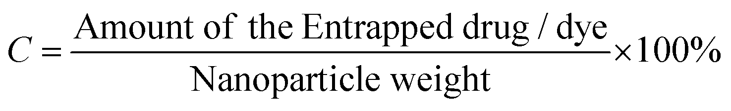
The phase of the product was identified by X-ray powder diffraction (X-ray diffractometer, Bruker USA D8 Advanced Davinci), using Cu Kα (λ = 0.15406 nm) and a solid-state NaI dynamic scintillation detector. The full Diffracplus software package was used for data acquisition, phase analysis, crystallography, and thin film characterization.Dye-encapsulation efficiency (EE) and loading capacity (LC)
RhB-PS1-SA spheres were prepared as reported above, and left to precipitate overnight. The aqueous medium was decanted and the emission intensity at the desired wavelength was measured. The dye-encapsulation efficiency (EE), which is correlated with the concentration of the dye not incorporated or the free unentrapped dye, can be expressed by eqn (1):36As the concentration of the dye is directly proportional to the emission intensity, eqn (2), the emission of the dye incorporated in nanoparticles is equal to the total emission subtracted by the emission intensity of the dye not incorporated; EE can be calculated using eqn (3):
The loading capacity (w/w %LC) can be calculated using the following expression:
 | (1) |
 | (2) |
 | (3) |
| 0.48 × EE = 0.48 × 61.56% = 0.2954 mg. |
| LC = (0.2954/1.5) × 100% = 19.7% |
Dynamic light scattering (DLS) analysis and zeta potential measurements
Dynamic light scattering (DLS) analysis and zeta potential measurements of the spherical assemblies formed by PS1 were performed using a Nano-zeta sizer (Horiba Sz-100) and these measurements were performed at room temperature, 25 °C.Cell culture and fluorescence imaging
Trypsinized HCT 116 (human colorectal cancer cell line) were seeded in Dulbecco's modified Eagle's medium (DMEM) supplemented with 10% fetal bovine serum and incubated at 37 °C with 5% CO2. Next, 3 × 10³ cells were added to each well in a 96-well culture plate. After having grown for 48 h, these cells were incubated with a solution of RhB-PS1-SA in aqueous PBS buffer (pH 7.2) for 16 h at 37 °C in the culture medium. After being washed three times with sterile PBS to remove unbound probe molecules, the cells were viewed under a laser scanning confocal microscope (Carl Zeiss). Finally, the cytotoxicity of the PS1 toward HCT 116 cells was determined by conventional MTT assays.Conflicts of interest
There are no conflicts of interest to declare.Acknowledgements
P. D. acknowledges the support of the Interdisciplinary Institute of Indian System of Medicine, SRM IST for confocal imaging studies. S. G. thanks Science and Engineering Research Board, Department of Science and Technology, Government of India for an Early Career Researcher Award (File No: ECR/2017/000060).Notes and references
- (a) G. M. Whitesides, J. P. Mathias and C. T. Seto, Science, 1991, 254, 1312–1319 CrossRef CAS PubMed; (b) J. M. Lehn, Science, 1993, 260, 1762–1763 CrossRef CAS PubMed; (c) J. Wang, K. Liu, R. Xing and X. Yan, Chem. Soc. Rev., 2016, 45, 5589–5604 RSC.
- (a) A. P. Alivisatos, K. P. Johnsson, X. Peng, T. E. Wilson, C. J. Loweth, M. P. Bruchez Jr and P. G. Schultz, Nature, 1996, 382, 609–611 CrossRef CAS PubMed; (b) C. A. Mirkin, R. L. Letsinger, R. C. Mucic and J. J. Storhoff, Nature, 1996, 382, 607–609 CrossRef CAS PubMed; (c) S. Vauthey, S. Santoso, H. Gong, N. Watson and S. Zhang, Proc. Natl. Acad. Sci. U. S. A., 2002, 99, 5355–53603 CrossRef CAS PubMed.
- (a) R. S. Langer and J. P. Vacanti, Science, 1993, 260, 920–926 CrossRef CAS PubMed; (b) J. J. Panda and V. S. Chauhan, Polym. Chem., 2014, 5, 4418–4436 RSC; (c) N. Habibi, N. Kamaly, A. Memic and H. Shafiee, Nano Today, 2016, 11, 41 CrossRef CAS PubMed.
- D. R. T. Jonathan, W. Steed and K. J. Wallace, Core Concepts in Supramolecular Chemistry and Nanotechnology, John Wiley & Sons, Ltd, Chichester, 2007, pp. 1–320 Search PubMed.
- (a) E. Dujardin and S. Mann, Bio-inspired Materials Chemistry, Adv. Mater., 2002, 14, 775–788 CrossRef CAS; (b) A. Fotin, Y. Cheng, P. Sliz, N. Grigorieff, S. C. Harrison, T. Kirchhausen and T. Walz, Nature, 2004, 432, 573–579 CrossRef CAS PubMed; (c) J. D. Hartgerink, E. Beniash and S. I. Stupp, Science, 2001, 294, 1684–1688 CrossRef CAS PubMed; (d) N. Nuraje, I. A. Banerjee, R. I. MacCuspie, L. Yu and H. Matsui, J. Am. Chem. Soc., 2004, 126, 8088–8089 CrossRef CAS PubMed; (e) K. Papanikolopoulou, G. Schoehn, V. Forge, V. T. Forsyth, C. Riekel, J. F. Hernandez, R. W. Ruigrok and A. Mitraki, J. Biol. Chem., 2004, 280, 2481–2490 CrossRef PubMed.
- (a) M. Yemini, M. Reches, J. Rishpon and E. Gazit, Nano Lett., 2005, 5, 183–186 CrossRef CAS PubMed; (b) Y. Ding, D. Li, K. Zhao, W. Du, J. Zheng and M. Yang, Biosens. Bioelectron., 2013, 48, 281–286 CrossRef CAS PubMed.
- (a) Y. Song, S. R. Challa, C. J. Medforth, Y. Qiu, R. K. Watt, D. Peña, J. E. Miller, F. V. Swol and J. A. Shelnutt, Chem. Commun., 2004, 1044–1045 RSC; (b) M. Reches and E. Gazit, Science, 2003, 300, 625–627 CrossRef CAS PubMed.
- X. Yan, Y. Cui, W. Qi, Y. Su, Y. Yang, Q. He and J. Li, Small, 2008, 4, 1687–1693 CrossRef CAS PubMed.
- V. Jayawarna, M. Ali, T. A. Jowitt, A. F. Miller, A. Saiani, J. E. Gough and R. V. Ulijn, Adv. Mater., 2006, 18, 611–614 CrossRef CAS.
- (a) M. Li, D. C. Green, J. L. R. Anderson, B. P. Binks and S. Mann, Chem. Sci., 2011, 2, 1739–1745 RSC; (b) R. K. Kumar, M. Li, S. N. Olof, A. J. Patil and S. Mann, Small, 2013, 9, 357–362 CrossRef CAS PubMed.
- (a) P. Stano, P. Carrara, Y. Kuruma, T. P. de Souza and P. L. Luisi, J. Mater. Chem., 2011, 21, 18887–18902 RSC; (b) V. Noireaux and A. Libchaber, Proc. Natl. Acad. Sci. U. S. A., 2004, 101, 17669–17674 CrossRef CAS PubMed.
- (a) E. G. Bellomo, M. D. Wyrsta, L. Pakstis, D. J. Pochan and T. J. Deming, Nat. Mater., 2004, 3, 244–248 CrossRef CAS PubMed; (b) P. Koley, A. Gayen, M. G. B. Drew, C. Mukhopadhyay and A. Pramanik, Small, 2012, 8, 984–990 CrossRef CAS PubMed; (c) K. Liu, R. Xing, Q. Zou, G. Ma, H. Möhwald and X. Yan, Angew. Chem., Int. Ed., 2016, 55, 3036–3039 CrossRef CAS PubMed; (d) H. Zhang, J. Fei, X. Yan, A. Wang and J. Li, Adv. Funct. Mater., 2015, 25, 1193–1204 CrossRef CAS; (e) S. Ghosh, M. Reches, E. Gazit and S. Verma, Angew. Chem., Int. Ed., 2007, 46, 2002–2004 CrossRef CAS PubMed; (f) D. G. Fatouros, D. A. Lamprou, A. J. Urquhart, S. N. Yannopoulos, I. S. Vizirianakis, S. Zhang and S. Koutsopoulos, ACS Appl. Mater. Interfaces, 2014, 6, 8184–8189 CrossRef CAS PubMed.
- (a) S. Ghosh, S. K. Singh and S. Verma, Chem. Commun., 2007, 2296–2298 RSC; (b) B. S. Kim, D. Je. Hong, J. Bae and M. Lee, J. Am. Chem. Soc., 2005, 127, 16333–16337 CrossRef CAS PubMed; (c) R. Bucci, P. Das, F. Iannuzzi, M. Feligioni, R. Gandolfi, M. L. Gelmi, M. Reches and S. Pellegrino, Org. Biomol. Chem., 2017, 15, 6773–6779 RSC.
- (a) X. Yan, Q. He, K. Wang, L. Duan, Y. Cui and J. Li, Angew. Chem., Int. Ed., 2007, 46, 2431–2434 CrossRef CAS PubMed; (b) P. Moitra, Y. Subramanian and S. Bhattacharya, J. Phys. Chem. B, 2017, 121, 815–824 CrossRef CAS PubMed; (c) P. Moitra, K. Kumar, P. Kondaiah and S. Bhattacharya, Angew. Chem., Int. Ed., 2014, 53, 1113–1117 CrossRef CAS PubMed; (d) J. Naskar and A. Banerjee, Chem.– Asian J., 2009, 4, 1817–1823 CrossRef CAS PubMed.
- (a) J. Kim, T. H. Han, Y. I. Kim, J. S. Park, J. Choi, D. G. Churchill, S. O. Kim and H. Ihee, Adv. Mater., 2010, 22, 583–587 CrossRef CAS PubMed; (b) P. Zhu, X. Yan, Y. Su, Y. Yang and J. Li, Chem. – Eur. J., 2010, 16, 3176–3183 CrossRef CAS PubMed; (c) P. Das and M. Reches, Nanoscale, 2016, 8, 9527–9536 RSC.
- P. P. Bose, A. K. Das, R. P. Hegde, N. Shamala and A. Banerjee, Chem. Mater., 2007, 19, 6150–6157 CrossRef CAS.
- A. Ajayaghosh, R. Varghese, S. Mahesh and V. K. Praveen, Angew. Chem., Int. Ed., 2006, 45, 7729–7732 CrossRef CAS PubMed.
- A. Brizard, C. Aimé, T. Labrot, I. Huc, D. Berthier, F. Artzner, B. Desbat and R. Oda, J. Am. Chem. Soc., 2007, 129, 3754–3762 CrossRef CAS PubMed.
- M. Reches and E. Gazit, Nano Lett., 2004, 4, 581–585 CrossRef CAS.
- (a) E. Gzit, Chem. Soc. Rev., 2007, 36, 1263–1269 RSC; (b) K. Tao, A. Levin, L. A. Abramovich and E. Gazit, Chem. Soc. Rev., 2016, 45, 3935–3953 RSC; (c) E. D. Santis and M. G. Ryadnov, Chem. Soc. Rev., 2015, 44, 8288–8300 RSC; (d) L. A. Abramovicha and E. Gazit, Chem. Soc. Rev., 2014, 43, 6881–6893 RSC.
- (a) A. Maity, A. Dey, M. K. Si, B. Ganguly and A. Das, Soft Matter, 2018, 14, 5821–5831 RSC; (b) A. Maity, A. Dey, M. Gangopadhyay and A. Das, Nanoscale, 2018, 10, 1464–1473 RSC.
- S. Y. Fung, C. Keyes, J. Duhamel and P. Chen, Biophys. J., 2003, 85, 537–548 CrossRef CAS PubMed.
- (a) S. Vauthey, S. Santoso, H. Gong, N. Watson and S. Zhang, Proc. Natl. Acad. Sci. U. S. A., 2002, 99, 5355–5360 CrossRef CAS PubMed; (b) S. Santoso, W. Hwang, H. Hartman and S. Zhang, Nano Lett., 2002, 2, 687–691 CrossRef CAS.
- S. Maity, P. Jana, S. K. Maity and D. Haldar, Langmuir, 2011, 27, 3835 CrossRef CAS PubMed.
- S. Yuran, Y. Razvag and M. Reches, ACS Nano, 2012, 6, 9559–9566 CrossRef CAS PubMed.
- (a) A. M. Smith, R. J. Williams, C. Tang, P. Coppo, R. F. Collins, M. L. Turner, A. Saiani and R. V. Ulijn, Adv. Mater., 2008, 20, 37–41 CrossRef CAS; (b) M. Crisma, C. Toniolo, S. Royo, A. I. Jiménez and C. Cativiela, Org. Lett., 2006, 8, 6091–6094 CrossRef CAS PubMed; (c) X. Yan, P. Zhu and J. Li, Chem. Soc. Rev., 2010, 39, 1877–1890 RSC.
- X. Yan, Y. Cui, Q. He, K. Wang, J. Li, W. Mu, B. Wang and Z. O. Yang, Chem. – Eur. J., 2008, 14, 5974–5980 CrossRef CAS PubMed.
- (a) A. V. Dobrynin, M. Rubinstein and S. P. Obukhov, Macromolecules, 1996, 29, 2974–2979 CrossRef CAS; (b) J. Jeon and A. V. Dobrynin, Macromolecules, 2007, 40, 7695–7706 CrossRef CAS.
- A. V. Dobrynin and M. Rubinstein, Prog. Polym. Sci., 2005, 30, 1049–1118 CrossRef CAS.
- J. Wang, C. Yuan, Y. Han, Y. Wang, X. Liu, S. Zhang and X. Yan, Small, 2017, 13, 1702175 CrossRef PubMed.
- (a) L. M. Gordon, P. W. Mobley, R. Pilpa, M. A. Sherm and A. J. Waring, Biochim. Biophys. Acta, 2002, 1559, 96–120 CrossRef CAS; (b) E. Cerf, R. Sarroukh, S. T. Kato, L. Breydo, S. Derclaye, Y. F. Dufrêne, V. Narayanaswami, E. Goormaghtigh, J. M. Ruysschaert and V. Raussens, Biochem. J., 2009, 421, 415–423 CrossRef CAS PubMed.
- (a) K. A. Feeney, N. Wellner, S. M. Gilbert, N. G. Halford, A. S. Tatham, P. R. Shewry and P. S. Belton, Biopolymers, 2003, 72, 123–131 CrossRef CAS; (b) J. Kong and S. Yu, Acta Biochim. Biophys. Sin., 2007, 39, 549–559 CrossRef CAS PubMed.
- D. M. Byler and H. Susi, Biopolymers, 1986, 25, 469–487 CrossRef CAS.
- (a) P. Das, I. Pan, E. Cohenc and M. Reches, J. Mater. Chem. B, 2018, 6, 8228–8237 RSC; (b) C. A. E. Hauser, R. Deng, A. Mishra, Y. Loo, U. Khoe, F. Zhuang, D. W. Cheong, A. Accardo, M. B. Sullivan, C. Riekel, J. Y. Ying and U. A. Hauser, Proc. Natl. Acad. Sci. U. S. A., 2011, 25, 1361–1366 CrossRef PubMed.
- L. V. Rubinstein, R. H. Shoemaker, K. D. Paull, R. M. Simon, S. Tosini, P. Skehan, D. A. Scudiero, A. Monks and M. R. Boyd, J. Natl. Cancer Inst., 1990, 82, 1113–1117 CrossRef CAS PubMed.
- (a) Z. Zhang and S. S. Feng, Biomaterials, 2006, 27, 4025–4033 CrossRef CAS PubMed; (b) B. Chu, L. Zhang, Y. Qu, X. Chen, J. Peng, Y. Huang and Z. Qian, Sci. Rep., 2016, 6, 34069 CrossRef CAS PubMed.
Footnote |
| † Electronic supplementary information (ESI) available: Details of the synthetic procedures, NMR, mass, FT-IR characterization, AFM analysis, zeta potential analysis, DLS measurement, SEM analysis, XRD analysis, cell diffusion study and procedure of MTT assay. See DOI: 10.1039/c9qm00363k |
| This journal is © the Partner Organisations 2019 |