
 Open Access Article
 This Open Access Article is licensed under a
 Creative Commons Attribution 3.0 Unported Licence
Cryogenic toughness of natural silk and a proposed structure–function relationship†
Chengjie
Fu‡
a,
Yu
Wang‡
a,
Juan
Guan
b,
Xin
Chen
 a,
Fritz
Vollrath
c and
Zhengzhong
Shao
*a
a,
Fritz
Vollrath
c and
Zhengzhong
Shao
*a
aState Key Laboratory of Molecular Engineering of Polymers, Advanced Materials Laboratory, Department of Macromolecular Science, Fudan University, Shanghai 200433, People's Republic of China. E-mail: zzshao@fudan.edu.cn
bSchool of Materials Science and Engineering, Beijing Innovation Center of Biomedical Engineering, Beihang University, No. 37 Xue Yuan Road, Haidian District, Beijing 100191, People's Republic of China
cDepartment of Zoology, University of Oxford, South Parks Road, Oxford OX1 3PS, UK
First published on 3rd October 2019
Abstract
Natural spider and worm silks can provide key insights into bio-polymer technology. No-one would have thought that ductility and toughness at cryogenic temperatures would be among their properties. Here we examine the behavior and function of several animal silks by focusing on the multi-fibrillar fibres of Antheraea pernyi silkworm cooled down to −196 °C. In essence, on the micro- and nanoscale, the extrinsic toughening mechanism of the aligned nanofibrils of silk-protein blunts the crack tip and deviates the fracture path. At the molecular level, an intrinsic toughening mechanism within each nanofibril can be attributed to high degrees of orientation of both ordered and disordered chain-domains. We propose that the highly aligned yet relatively independent nanofibrillar structure allows the partly frozen molecular chain at cryogenic temperature to be activated to induce crack blunting, to allow fibril slipping, and to facilitate the effective unfolding of silk fibroin molecular chains thus preventing or delaying brittle failure of the whole fibre. The spider and mulberry silks examined diplayed comparable functional mechanisms. We envision that our study will lead to the design and fabrication of new families of tough structural composites using natural silk or silk-inspired filaments for testing applications even at arctic or indeed outer-space conditions.
1. Introduction
Natural structural materials such as silks, bones, teeth, nacres, and wood can exhibit surprising mechanical performances often derived from an unusual combination of strength and extensibility leading to exceptional toughness.1,2 The underlying mechanism is the synergistic interaction of multiple actors operating at different length scales.3,4 The complex structural architectures in natural systems, including hierarchies and interface interactions, have provided ample inspiration for the attempt to manufacture synthetic counterparts that aim to mimic the biological structure and function.5–8 Silks are a perfect case in point.9,10 Like other natural structural materials, silks utilize hierarchical architectures over many length scales in the “structure–property-function” paradigm. In silks, anti-parallel β-sheet nanocrystals are embedded within less orderly amorphous domains to form a multi-protein composite structured at the nanometre scale. This composite is further organized into fibrils at scales of tens to hundreds of nanometers, which in turn pack into fibril bundles that make up at micrometre dimensions the silk fibre as we know it.11,12 It is this multi-layer and hierarchical structuring of a natural silk that is responsible, so it is assumed, for the enviable mechanical properties of the material.11,13–15A benchmark spider silk, for example, was shown to increase in both strength and extensibility down to −60 °C14 while under the same conditions synthetic polymers including rubbers lose mechanical toughness.16,17 Importantly, the mechanisms behind the extraordinary high-rate energy absorption18 and low temperature toughness14 of silks are far from being understood despite some early work on low T ductility in synthetic elastomers.19–21 Here we outline a systematic examination of the toughness of natural silks over a broad temperature range and study their possible toughening mechanisms.
Our study focuses on silk of the wild silkworm Antheraea pernyi (A. pernyi). This silk is especially interesting because its protein sequence is similar to that of the dragline silk of the Nephila spider,22 which is the benchmark for spider silks. Yet the A. pernyi filaments are much thicker, which allows the use of a wider range of mechanical tests.23–25 We measured the fibre fracture behaviour, fractography, and energy absorption of forcibly-reeled A. pernyi silk and compared this with native and synthetic analogues including Nephila spider dragline silk, Bombyx mori (B. mori) cocoon silk and A. pernyi cocoon silk as well as synthetic fibres with oriented molecular structure. It is our aim to elucidate the contribution of the molecular structure to the silk's mechanical properties specifically ductility and toughness at cryogenic temperatures.
2. Results and discussion
2.1. Ductility and toughness of A. pernyi silk at sub ambient temperatures
The tensile mechanical properties of the as-reeled A. pernyi silks were characterised at T ranging from room temperature down to liquid nitrogen temperature of −196 °C with all the fibres being forcibly reeled following a procedure established in ref. 13 and 26.Fig. 1a and b show the representative stress–strain profiles of A. pernyi silk fibres taken from the same silkworm measured at −196 °C and at room temperature respectively. Both the yield stress and the breaking stress at −196 °C increased, and the breaking strain remained as high as 30.7 ± 3.5%. The tensile modulus of the silk fibres increased from 14.5 ± 0.8 GPa at room temperature to 18.3 ± 0.5 GPa at −196 °C, while the breaking energy of the silk (calculated from the area under the stress–strain curve) doubled from 154 ± 15 MJ m−3 to 339 ± 52 MJ m−3. In addition, examining fibre hysteresis showed that unloading at 17% strain and re-loading at both room temperature and cryogenic temperature did not appear to change the overall shape of the stress–strain profiles. The silk displayed a higher “elasticity” in liquid nitrogen, with a strain recovery and work recovery of 70.7 ± 0.2% and 53.5 ± 1.7%, respectively, compared to 40.7 ± 0.7% and 31.6 ± 0.4% at room temperature.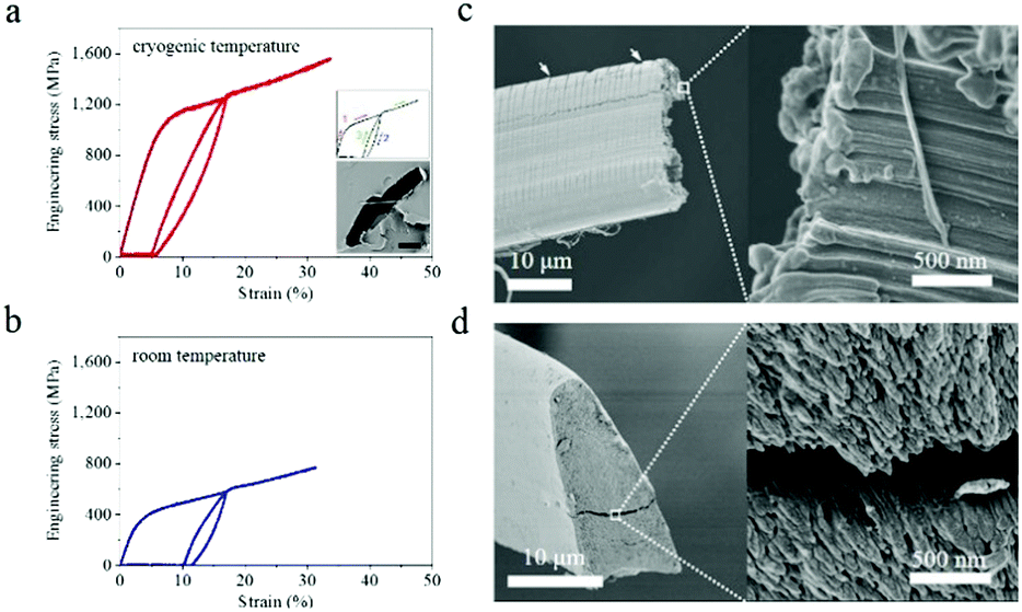 | ||
| Fig. 1 (a and b) Tensile stress–strain curve with one unloading and reloading cycle of A. pernyi silk at −196 °C (a) and room temperature (b). Inserts are the formation of the cyclic curve (1: loading, 2: unloading, 3: reloading) and the cross section of the silk-embedded epoxy resin. The scale bar represents 10 μm. (c and d) Fracture end of silk broken in liquid nitrogen (c) and in nitrogen gas at room temperature (d). The sericin layer of the silk fibre shows many transverse cracks indicated by arrows. Enlarged image shows that the granular morphology is the tip of the nanofilaments which feature a “mushroom cap” (c) and “tapered end” (d). Repeated tests were conducted with n = 8 for both room temperature and −196 °C. | ||
Fracture morphology underlined the measured increase in the elastic deformation restoration at low temperatures. Fig. 1c and d show two distinct fracture-end features of nanofilaments, i.e. “mushroom cap” and “tapered end”, which were observed at liquid nitrogen temperature and room temperature, respectively. Such differences in the fractography also reveal details of the energy-storing ability of A. pernyi silk at different temperatures. In particular, after an initial stretch to 17% and beyond the yield, the stored elastic energy of silk at −196 °C was approximately 3.5 times that at room temperature, as calculated from Fig. 1a and b. Such a high energy release prior to a break at −196 °C was likely to cause a very powerful snap-back of the material to result in the mushroom cap morphology, while a lower energy release at room temperature gave rise to the tapered end shape.27 We note that the tensile properties of the as-reeled A. pernyi silks at cryogenic temperatures and the ductility feature discussed are independent of the intra-individual variability, but may vary subject to inter-individual variability or excess moisture treatment, to be discussed later. Indeed, the generic intra- and inter-individual variability in the tensile properties of A. pernyi silk fibres at room temperature is discussed elsewhere in detail24 while here we focus on the generic relationship between the structure and cryogenic ductility of A. pernyi silk. Fig. S1 (ESI†) shows more stress–strain profiles of A. pernyi silks at intermediate temperatures between −196 °C and 20 °C in order to confirm the observation that the breaking strain of A. pernyi silk did not decrease with decreasing temperature.
2.2. Comparison with other silk species and synthetic analogues
For comparison with the as-reeled A.pernyi silks we measured the mechanical properties of reeled Nephila spider dragline silks and unravelled B. mori cocoon silks. Surprisingly, these two kinds of silks exhibited a higher ductile failure at low temperatures (Fig. S2, ESI† and ref. 28). Detailed analysis of the tensile stress and breaking energy of spider dragline silks and B. mori silkworm silks showed that with decreasing T they at first increased and then decreased (Fig. 2a and b), which differs from the behavior of the as-reeled A. pernyi silks which show gradually increased tensile stress and breaking energy with decreasing temperature. The differences in the low temperature ductility of the three silks indicate a special feature in the structural organization of the as-reeled A. pernyi silks, to be discussed later.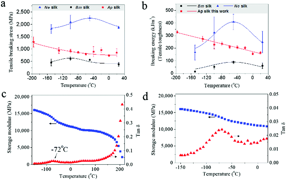 | ||
Fig. 2 (a and b) Responses of tensile stress (a) and breaking energy (b) for the as-reeled A. pernyi silks, reeled spider silks, and unravelled B. mori cocoon silks. (c and d) DMTA profile of the as-reeled A. pernyi silk showing temperature dependence of storage modulus and tan![[thin space (1/6-em)]](https://www.rsc.org/images/entities/char_2009.gif) δ at 1 Hz (c) and enlarged view of the β-relaxation at −72 °C (d). δ at 1 Hz (c) and enlarged view of the β-relaxation at −72 °C (d). | ||
The feature of low-T ductility of A. pernyi silk distinguishes it significantly from the typical synthetic polymeric fibres which show a strength–ductility trade-off with temperatures dropping to the cryogenic level of −196 °C.17,29 This means that any increased modulus and strength would come at the cost of decreased ductility. Fig. S3 (ESI†) shows the stress–strain behaviours of man-made high tenacity nylon fibres at room temperature and −196 °C that show a 7% drop in the maximum tensile strain and break before the primary yield point at −196 °C.
2.3. Structure mechanisms for the cryogenic toughness of A. pernyi silk
The β-relaxation around −70 °C is associated with peptide–water interactions and is thought to be the origin of the low-T (−60 °C) toughness of spider silk.14 Dynamic mechanical thermal analysis (DMTA) also shows comparable relaxation in B. mori silk (−60 °C)30 and is confirmed for A. pernyi silk at −72 °C as shown in Fig. 2c and d. The question arises of how group movement associated with the β-relaxation is not frozen at cryogenic temperatures.Most, perhaps all, natural silks possess the distinct fibrillar morphology well demonstrated for spider31,32 and silkworm silks.12A. pernyi silk also displays this distinctive anisotropic micro- and nano-fibrillar morphology (Fig. 3a). A. pernyi silk micro-fibrils are readily peeled along the fibre axis revealing split nanofibrils inside any broken fibres demonstrating well aligned independent micro- and nanofibrils.33 The nanofibrils observed measured 10–20 nm in diameter (Fig. 3a) which was significantly smaller than the previous recordings of A. pernyi nanofilaments in the region of 90–170 nm.34,35 The independence of nanofibrils from the A. pernyi micro-fibrils was confirmed by ambient and low-T fracture morphology (Fig. 1c and d). The animal fibre's micro/nano fibrillar structure is distinct from the morphology of high tenacity nylon 6,6 fibre, in which finer filaments cannot be separated by peeling (Fig. S4, ESI†).
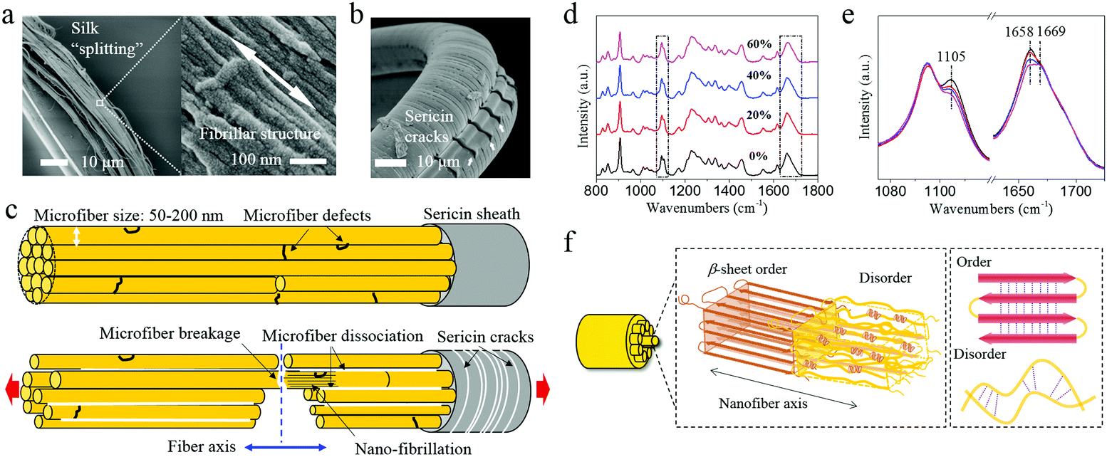 | ||
| Fig. 3 Antherea pernyi silk micro- and nano-structure. (a) Microfibres formed by peeling a silk fibre and the morphology of oriented nanofibrils indicated by the white double-arrow in the microfibres. (b) Transverse cracks of the sericin skin of the fibre. Arrows indicate the broken parts which are separated from the core fibre by longitudinal cracks. (c) Schematic presentation of the microfibre morphology of A. pernyi silk (top) and the deflected fracture path originated from a crack on the interface between sericin and the silk core (bottom). (d) Raman spectra of A. pernyi silk with different pre-strains at cryogenic temperature. (e) Enlarged image of the rectangular area in (d) showing the decrease of peaks at 1658 cm−1 and 1105 cm−1 that are assigned to the α-helix structure and showing the peak at 1669 cm−1 that is assigned to the β-sheet structure. (f) Schematic of the hierarchical structure of A. pernyi silk fibre. | ||
Moreover, unlike Nylon and spider silk, but like B. mori silk, the as-reeled A. pernyi silk carries a substantial sericin skin-layer coating that (as a bave) holds the two single silk filaments (each called a brin). This sericin coating itself shows many transverse cracks when strongly bent at −196 °C (Fig. 3b or Fig. 1c) which is indicative of brittle fracture. The sericin skin of the bave thread affects the fracture behaviour of the fibroin brin fibre by controlling the intra-thread humidity as discussed later.
The Cook-Gordon mechanism of fracture mechanics suggests that a weak interface parallel to the applied force will open just in front of the approaching crack thus blunting and deflecting it – if the crack-containing material is highly anisotropic.36,37 This mechanism is temperature independent and thus highly relevant to our study given that the A. pernyi silk fibre is indeed a highly anisotropic material as shown by its polarized Raman spectra and X-ray diffraction patterns (Fig. S5 and S6, ESI†). Moreover, the observation that the micro- and nanofibrils in A. pernyi silk can be separated easily suggests weak interactions derived from van der Waals and other weak intermolecular forces. Thus, through separation or splitting of the fibrils, the crack path could be effectively deflected into the interfibrillar spaces, which is a process that can absorb fracture energy by (i) blunting the crack tip as well as (ii) inducing mutual slipping between micro- and nanofibrils. In both cases energy would be dissipated without failure in the bulk material. Fig. 3c outlines schematically how a crack initiated on the silk surface, presumably from the brittle sericin skin in Fig. 3b, follows a deflected path across the fibroin core whenever it meets an interfibrillar junction parallel to the applied force. As the crack passes across the cross section, more parallel cracks would develop and less energy would be carried by the major crack. As a result, the fracture or cracks are developed in a 3D topological manner rather than a simple 1D path or 2D plane.
In addition to the morphology level mechanisms discussed so far there are of course also molecular level mechanisms at play related (somehow) to the complex and presumably highly evolved structural organization at the molecular scale.11,12,38 The mushroom-end and tapered-end fracture morphologies of the fibrils in A pernyi silk suggest an internal ability to deform both elastically and plastically under low-T, an ability that should be governed by structural changes at the molecular level. To examine the molecular chain movement at cryogenic temperatures we stretched silk fibres to different strains in liquid nitrogen and examined them with Raman spectroscopy. The data in Fig. 3d and e show conformational changes at 1658 cm−1 and 1105 cm−1 of the α-helix conformation.23 Clearly, the tensile pre-strain induced decrease in the α-helix conformation (non-recoverable) indicates activation of the segmental motions in the amorphous structure. Molecular relaxations, i.e. the hydrogen bond disassociation within the helical conformers, might further contribute to the plastic deformation and energy dissipation in silk fibrils at cryogenic temperatures. As illustrated in Fig. 3f, a structural hierarchy including (i) firstly micro- and nanofibrillar structure and (ii) secondly two characteristic molecular structural phases is proposed for A. pernyi silks. The Order–Disorder two-phase structure model15,39 is adopted (for its simplicity and transparency) to describe the molecular structure within the fibrils of A. pernyi silks. This model concurs with the previous hypotheses such as the string of beads theory and the non-periodic lattice theory.39–41
Archetypal silks, such as spider dragline, mulberry cocoon and wild-silk cocoon fibres, are thought to possess similar structure–property relations.22 Importantly, the three mentioned silks differ, if only marginally, in nanofibril morphology and interface interactions. The spider silk would have stronger interface interactions between the nanofibrils than the other two silks because of its overall thinness. This hypothesis is supported by the observation that no microfibrils (bundles of nanofibrils) and longitudinal cracks were observed after the spider silk broke at room temperature or cryogenic temperature.14 The B. mori cocoon silk also shows microfibril structures,35 but has underlying “defects” arising from the “figure of eight” spinning what would lead to irregular nanofibril arrangement and interface interactions. Importantly, unlike the as-reeled A. pernyi, it's cocoon silk also shows decreased toughness with decreased temperature.28 This suggests that the distinct mechanical behaviour of the as-reeled A. pernyi silk in low-T conditions is based on the details of the micro-/nanofibrillar morphology (originating from the reeling i.e. spinning conditions) which in turn significantly affects the crack blunting behaviour and thus the ductile/brittle fracture mode.
2.4. The synergistic role of crack blunting
As proposed above, the weak interactions between highly oriented nanofibrils of A. pernyi silk guarantee the effective blunting of the crack and prevent catastrophic breakage at cryogenic temperatures. The free-water content (moisture) in silk may affect not only the molecular structure of silk but also the micromechanics in the fracture behaviour, and thus the crack blunting ability of silk. Fig. 4a–c demonstrates the moisture effect on the tensile behaviour at low-T. The dry silk in Fig. 4a displayed ductile failure for the core fibroin brin fibre and brittle failure for the outside layer of the sericin bave skin. When the silk was conditioned under 40% relative humidity (containing ∼5% bound water) the behaviour of the brin fibre changed to semi-ductile fracture (Fig. 4b). The outside layer of about 1 μm thick broke with a clean brittle fracture while the inside core continued to break in a ductile fashion. With saturated moisture (containing as much as 30 wt% water42), the silk in Fig. 4c broke at −196 °C with a much smoother fracture surface. One might hypothesise that the fracture energy of the sericin layer itself increases with increasing moisture content. Moisture also affects both the inter-fibrillar and inter-molecular space in the amorphous structure of silk through lubrication by water molecules, both of which impairs the crack blunting mechanism from the nanofibrils. Together these effects induce the core silk fibre to change fracture mode from ductile to brittle. However, when the bave's sericin skin was removed by degumming, the cryogenic tensile behaviour of the degummed brin fibre showed little relationship to the moisture treatment, no matter how much moisture was absorbed. Fig. S7 (ESI†) shows the fractograph and rough fracture surface of degummed fibres that broke at −196 °C, which suggests that, although moisture can trigger the structure change in silk,25,26 water-content itself seems in-sufficient to render the fracture mode of degummed A. pernyi silk from ductile to brittle because there is no crack initiator on the surface of the fibre.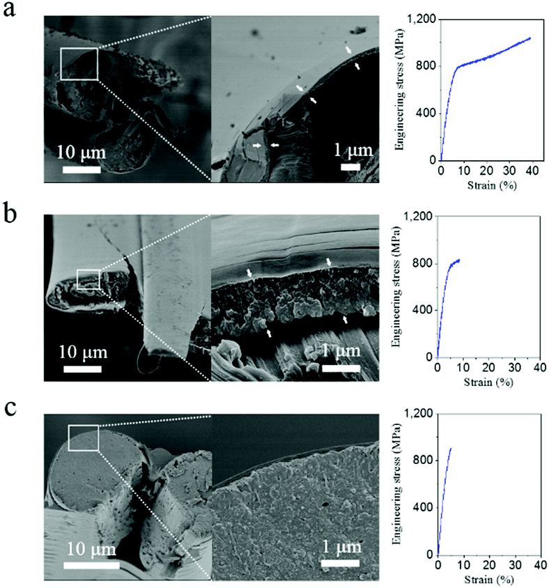 | ||
| Fig. 4 Antherea pernyi silk fracture morphology (left) and representative stress–strain curve (right) broken at cryogenic temperature −196 °C with different atmospheric treatments: (a) dry nitrogen purge for 20 min; (b) 43% relative humidity under room conditions; (c) moisture saturated nitrogen gas purge for 20 min. Arrows in (a) and (b) indicate the layer of initial cracks separated from the core fibre by the longitudinal crack. | ||
To test the effect of crack propagation at low-T, we introduced a micron-sized notch into an A. pernyi bave. Fig. S8 (ESI†) shows the fracture of such a notched fibre despite it was dry breaking in a semi-ductile mode i.e. like a wet silk (see Fig. 4b). This suggests that, when a defect/crack size reaches a critical value, the fracture energy becomes so large that the crack blunting mechanism through fibrillar separation and molecular relaxation mechanism cannot reverse the catastrophic failure. This would further suggest that critical defects carrying enough breaking energy (i.e. brittle sericin layer, artificial/natural notches) could induce the brittle fracture of the as-reeled A. pernyi silk.
2.5. The synergistic role of molecular chain extension
To examine the effect of fibrillar as well as molecular variability, we investigated three examples of as-reeled A.pernyi silks with different degrees of molecular order ranging from 60% to 35% (Fig. 5).23–25 These three types of silk fibres were obtained from different individual silkworms under identical spinning conditions. Structural analysis demonstrated that silk fibre 1 (SF1) possessed a lower molecular chain orientation and more α-helix structure in the disordered phase than SF2 and SF3 (inserts in Fig. 5a and Fig. S9, ESI†).24 The stress–strain curves at −196 °C (Fig. 5a) show that all the threads showed ductile failure while the breaking strain decreased significantly from SF1 to SF3. In addition, SF3 displayed drastically reduced breaking strain at −196 °C compared to room temperature (Fig. 5b). These results indicate that A. pernyi silk fibre with more disordered molecular chains (more α-helix structure) tends to retain cryogenic ductility probably due to an intrinsic/molecular extension mechanism. In summary, the synergistic effect of the extrinsic and intrinsic toughening mechanism provides the as-reeled A. pernyi silk with its enviable ductility and toughness at cryogenic temperatures.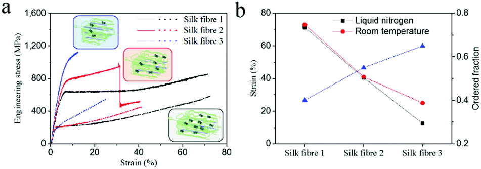 | ||
| Fig. 5 (a) Typical stress–strain curves of three representative A. pernyi silks with decreased amorphous structure fraction at liquid nitrogen temperature (solid curve) and room temperature (dotted curve). Inserts show the corresponding structure models. (b) Calculated strain values and ordered fraction. The ordered fraction is obtained from ref. 24 and was calculated using Group Interaction Modelling. | ||
3. Experimental
3.1. Silk fibre preparation
Silk fibre was forcibly reeled at 8 mm s−1 as reported previously13,26 from mature A. pernyi silkworms collected from oak trees in a commercial tussah-silk plantation of Shandong Province, China. Silk fibres from more than 5 silkworms (two seasons) were collected and tested. With the help of dividers, single silk fibres (baves) with a gauge length of 9 mm were transferred to (and affixed to with double-faced tape) the sample frame43 made from hard cardboard. To prepare degummed silk, the as-reeled A. pernyi silk fixed between tips of dividers with nail varnish was submerged into a hot (95–100 °C) 0.5% NaHCO3 aqueous solution for 15 min and subsequently into hot (95–100 °C) deionized water and cold deionized water for 8 min respectively. To obtain notched silk, the as-reeled A. pernyi silk was fixed horizontally and tautly by dividers, and a piece of scalpel connected to 2.5 N load cell of Instron 5565 approached the silk vertically and cut it at the middle part at a rate of 0.005 mm s−1. When the force on the scalpel reached ca. 0.002 N, it was retreated.For comparison, Bombyx mori (B. mori) silk fibres were obtained from cocoons from Jiangsu Province, China. Nephila edulis (N. edulis) spider dragline silks were forcibly reeled at 10 mm s−1 speed under lab conditions in Oxford (20 °C, relative humidity 40%) as detailed in earlier work.30 Six B. mori silk specimens were prepared using a similar method to that for A. pernyi silks for tensile test at each temperature, and five N. edulis spider silk specimens were prepared for each temperature.
3.2. Cross-sectional area measurement
A length of silk fibre (ca. 50 mm) was sputtered with gold for 3 min, then embedded in epoxy resin. The silk-embedded epoxy resin was fractured to six segments perpendicular to the silk fibre using the custom-built fracture tools. The fracture cross section was sputtered with gold, and then observed under Tescan 5136MM using back scattering electrons at 10 kV. The gold layer between the silk fibre and resin effectively weakens the interface adhesion so that the fibre will be easily pulled out during the fracture and leave a hole on the cross section. From this hole we estimated the cross-sectional area of the silk fibre using software Vega TC that comes with the SEM. Usually, 3–5 usable cross-sectional images can be obtained from a single silk fibre for area measurement. The average area was used as the cross-sectional area of neighbouring silk fibres.3.3. High-resolution SEM observation
A Hitach S4800 was used to obtain high-resolution SEM images. To study the fractography of the A. pernyi silk, fibres broken in tensile tests were carefully affixed to the side of SEM stubs with the fracture end pointing upward. To observe the inside structure of the A. pernyi silk, a strip of the fibre was carefully peeled apart under an optical microscope using pointed tweezers and then adhered on the SEM stub.3.4. Dynamic mechanical thermal analysis (DMTA)
The silk fibre adhered on the hard cardboard was fixed on the film tensile clamp of a TA Q800 DMA. The test was performed at 1 Hz with a temperature ramp rate of 3 °C min−1 under nitrogen atmosphere.3.5. Tensile test with TA Q800
A TA Q800 (static force control/strain rate mode) was utilized to analyse the tensile behaviour of silk fibre at sub ambient temperatures between room temperature and −196 °C. The silk fibre was first cooled with cold nitrogen gas (from liquid nitrogen) to the desired temperature and equilibrated for 2 min, and then tested at a strain rate of 0.0005 s−1 with a gauge length of 5 mm. The tensile test was repeated for more than 5 fibre specimens from the same silkworm individual.3.6. Tensile test with Instron
The sample frame was fixed with film clamps from a Netzsch DMA242 which was integrated with the custom-built low temperature accessory as shown in Fig. S10 (ESI†), which is different from the design in ref. 44. An Instron 5565 was applied for the tensile test at a strain rate of 0.005 s−1 if not otherwise indicated. A typical procedure for the test in liquid nitrogen was as following. The sample was first blown with dry or wet nitrogen for 20 min to obtain a certain amount of moisture, and then liquid nitrogen was poured into the low temperature accessory to cool the sample. After submerging the fibre for more than 6 min in liquid nitrogen, the tensile test was started. In the loading–unloading test, the sample was loaded to a strain of 17% and immediately unloaded to zero strain then reloaded to its breakage. The relaxation time between unloading and the next loading was 1 min. When the tensile test was finished, dry nitrogen was blown into the low temperature accessory until the temperature returned to room temperature, so that the morphology of the fracture end would not be changed by the condensed moisture. It should be noted that more than 5 samples were tested for each tensile test condition.3.7. Raman spectroscopy
Polarized Raman spectra of A. pernyi silk were collected using a Renishaw inVia Reflex spectrometer coupled to a Lieca microscope. The silk fibre was measured in the direction parallel or normal to the vibration direction of the laser beam. Spectra were obtained from ten acquisitions of 50 s using the 785 nm line of a semiconductor laser with an energy of approximately 300 mW. For each silk sample (5 mm long), more than three different positions were tested and the datum is effective if there is no variation in these spectra. The spectra were normalized by the intensity at 1615 cm−1 assigned to the phenyl group thought to arise mainly from the tyrosine residues, since it is insensitive to the conformation of the silk protein.453.8. X-ray diffraction (XRD)
A Rigaku D/Max-2550 PC powder diffractometer with Cu Kα irradiation (λ = 1.541 Å) was used to analyse the orientation of crystalline domains along the silk fibre axis. A bundle of aligned silks fixed on the custom-built sample holder was mounted to the sample stage, and then the diffraction intensity distribution pattern was obtained by Phi scan at 2θ = 16.8. The Hermans orientation coefficient fc was calculated according to the Wilchinsky orientation model.464. Conclusions
We conclude that the exceptional mechanical toughness (a combination of >1 GPa strength and >30% extensibility) of the as-reeled A. pernyi silk fibre at cryogenic temperatures derives from its highly aligned and oriented, relatively independent and extensible nanofibrillar morphology. On the morphological level, the “well-defined” micro- and nanofibrillar morphology imparts effective crack deflection and deviation along the interfibrillar space. On the molecular level, the highly oriented chain structure within the nanofibrils ensures high-elastic energy absorption from the order/disorder structural interactions and high-energy dissipation from molecular relaxations, for example via the unravelling of the α-helix in the disordered structure. We propose that the synergistic effect of the extrinsic (morphological) and intrinsic (molecular) toughening mechanism provides the as-reeled A. pernyi silk with its enviable toughness at cryogenic temperatures. We hope that this study will provide novel insights into understanding the structure–property relationships of natural high-performance materials and lead to ways of fabricating man-made polymers and composites for low temperature and high impact applications.Conflicts of interest
The authors declare no competing financial interest.Acknowledgements
This work was supported by the National Natural Science Foundation of China (NSFC 21574024, 21935002 and 51503009) and the Ministry of Science and Technology of China (2016YFA0203301) as well as the ERC (SP2-GA-2008-233409) and US-AFOSR (F49620-03-1-0111). This project has also received funding from the European Union's Horizon 2020 research and innovation programme under grant agreement No. 713475. J. G. acknowledges the Fundamental Research Funds for Central Universities. The authors are thankful to Dr Ruiwen Hao for providing the A. pernyi silkworm.Notes and references
- U. G. K. Wegst, H. Bai, E. Saiz, A. P. Tomsia and R. O. Ritchie, Nat. Mater., 2015, 14, 23–36 CrossRef CAS PubMed.
- J. S. Peng and Q. F. Cheng, Adv. Mater., 2017, 29, 1702959 CrossRef PubMed.
- F. Barthelat, Z. Yin and M. J. Buehler, Nat. Rev. Mater., 2016, 1, 16007 CrossRef CAS.
- M. A. Meyers, J. McKittrick and P. Y. Chen, Science, 2013, 339, 773–779 CrossRef CAS PubMed.
- E. Munch, M. E. Launey, D. H. Alsem, E. Saiz, A. P. Tomsia and R. O. Ritchie, Science, 2008, 322, 1516–1520 CrossRef CAS PubMed.
- B. Gludovatz, A. Hohenwarter, D. Catoor, E. H. Chang, E. P. George and R. O. Ritchie, Science, 2014, 345, 1153–1158 CrossRef CAS PubMed.
- L. B. Mao, H. L. Gao, H. B. Yao, L. Liu, H. Colfen, G. Liu, S. M. Chen, S. K. Li, Y. X. Yan, Y. Y. Liu and S. H. Yu, Science, 2016, 354, 107–110 CrossRef CAS PubMed.
- S. Ling, Z. Qin, C. Li, W. Huang, D. L. Kaplan and M. J. Buehler, Nat. Commun., 2017, 8, 1387–1898 CrossRef PubMed.
- F. G. Omenetto and D. L. Kaplan, Science, 2010, 329, 528–531 CrossRef CAS PubMed.
- C. J. Fu, Z. Z. Shao and V. Fritz, Chem. Commun., 2009, 6515–6529 RSC.
- S. Keten, Z. P. Xu, B. Ihle and M. J. Buehler, Nat. Mater., 2010, 9, 359–367 CrossRef CAS PubMed.
- G. Q. Xu, L. Gong, Z. Yang and X. Y. Liu, Soft Matter, 2014, 10, 2116–2123 RSC.
- Z. Z. Shao and F. Vollrath, Nature, 2002, 418, 741 CrossRef CAS PubMed.
- Y. Yang, X. Chen, Z. Z. Shao, P. Zhou, D. Porter, D. P. Knight and F. Vollrath, Adv. Mater., 2005, 17, 84–88 CrossRef CAS.
- D. Porter, F. Vollrath and Z. Shao, Eur. Phys. J. E: Soft Matter Biol. Phys., 2005, 16, 199–206 CrossRef CAS PubMed.
- T. Vukhanh and Z. Yu, Theor. Appl. Fract. Mech., 1997, 26, 177–183 CrossRef CAS.
- J. S. I. M. Ward, Mechanical properties of solid polymers, Wiley, Chichester, Sussex, 2012 Search PubMed.
- D. R. Drodge, B. Mortimer, C. Holland and C. R. Siviour, J. Mech. Phys. Solids, 2012, 60, 1710–1721 CrossRef.
- I. K. Park and H. D. Noether, Colloid Polym. Sci., 1975, 253, 824–839 CrossRef CAS.
- S. L. Cannon, G. B. Mckenna and W. O. Statton, J. Polym. Sci., Macromol. Rev., 1976, 11, 209–275 CrossRef CAS.
- W. Ren, Colloid Polym. Sci., 1992, 270, 943–955 CrossRef CAS.
- C. J. Fu, D. Porter, X. Chen, F. Vollrath and Z. Z. Shao, Adv. Funct. Mater., 2011, 21, 729–737 CrossRef CAS.
- Y. Wang, D. Porter and Z. Z. Shao, Biomacromolecules, 2013, 14, 3936–3942 CrossRef CAS PubMed.
- Y. Wang, J. Guan, N. Hawkins, D. Porter and Z. Z. Shao, Soft Matter, 2014, 10, 6321–6331 RSC.
- Y. Wang, J. C. Wen, B. Peng, B. W. Hu, X. Chen and Z. Z. Shao, Biomacromolecules, 2018, 19, 1999–2006 CrossRef CAS PubMed.
- C. J. Fu, D. Porter and Z. Z. Shao, Macromolecules, 2009, 42, 7877–7880 CrossRef CAS.
- J. W. S. Hearle, B. Lomas and W. D. Cooke, Atlas of Fibre Fracture and Damage to Textiles, Woodhead, Abington, 2nd edn, 1998 Search PubMed.
- K. Yang, S. J. Wu, J. Guan, Z. Z. Shao and R. O. Ritchie, Sci. Rep., 2017, 7, 11939 CrossRef PubMed.
- A. van der Wal, J. J. Mulder, H. A. Thijs and R. J. Gaymans, Polymer, 1998, 39, 5467–5475 CrossRef CAS.
- J. Guan, D. Porter and F. Vollrath, Biomacromolecules, 2013, 14, 930–937 CrossRef CAS PubMed.
- C. P. Brown, C. Harnagea, H. S. Gill, A. J. Price, E. Traversa, S. Licoccia and F. Rosei, ACS Nano, 2012, 6, 1961–1969 CrossRef CAS PubMed.
- Q. J. Wang and H. C. Schniepp, ACS Macro Lett., 2018, 7, 1364–1370 CrossRef CAS.
- J. Guan, W. Zhu, B. Liu, K. Yang, F. Vollrath and J. Xu, Acta Biomater., 2017, 47, 60–70 CrossRef CAS PubMed.
- O. Hakimi, D. P. Knight, M. M. Knight, M. F. Grahn and P. Vadgama, Biomacromolecules, 2006, 7, 2901–2908 CrossRef CAS PubMed.
- S. Putthanarat, N. Stribeck, S. A. Fossey, R. K. Eby and W. W. Adams, Polymer, 2000, 41, 7735–7747 CrossRef CAS.
- M. Raab and M. Sova, Collect. Czech. Chem. Commun., 1995, 60, 2006–2020 CrossRef CAS.
- M. Raab, E. Schulz and M. Sova, Polym. Eng. Sci., 1993, 33, 1438–1443 CrossRef CAS.
- W. W. Zhang, C. Ye, K. Zheng, J. J. Zhong, Y. Z. Tang, Y. M. Fan, M. J. Buehler, S. J. Ling and D. L. Kaplan, ACS Nano, 2018, 12, 6968–6977 CrossRef CAS PubMed.
- D. Porter and F. Vollrath, Adv. Mater., 2009, 21, 487–492 CrossRef CAS.
- C. Y. Hayashi, N. H. Shipley and R. V. Lewis, Int. J. Biol. Macromol., 1999, 24, 271–275 CrossRef CAS PubMed.
- D. Porter and F. Vollrath, Nano Today, 2007, 2, 6 CrossRef.
- K. H. Lee, Macromol. Rapid Commun., 2004, 25, 1792–1796 CrossRef CAS.
- G. R. Plaza, G. V. Guinea, J. Perez-Rigueiro and M. Elices, J. Polym. Sci., Part B: Polym. Phys., 2006, 44, 994–999 CrossRef CAS.
- E. M. Pogozelski, W. L. Becker, B. D. See and C. M. Kieffer, Int. J. Biol. Macromol., 2011, 48, 27–31 CrossRef CAS PubMed.
- G. Q. Zhou, Z. Z. Shao, D. P. Knight, J. P. Yan and X. Chen, Adv. Mater., 2009, 21, 366–370 CrossRef CAS.
- C. Riekel, C. Branden, C. Craig, C. Ferrero, F. Heidelbach and M. Muller, Int. J. Biol. Macromol., 1999, 24, 179–186 CrossRef CAS PubMed.
Footnotes |
| † Electronic supplementary information (ESI) available. See DOI: 10.1039/c9qm00282k |
| ‡ These authors contributed equally to this work. |
| This journal is © the Partner Organisations 2019 |