
CuSbSe2/TiO2: novel type-II heterojunction nano-photocatalyst†
Anuraj S.
Kshirsagar
 and
Pawan K.
Khanna
*
and
Pawan K.
Khanna
*
Nano Chemistry and Quantum Dots R & D Lab, Department of Applied Chemistry, Defence Institute of Advanced Technology (DIAT), Ministry of Defence, Govt. of India, Girinagar, Pune 411025, India. E-mail: pawankhanna2002@yahoo.co.in
First published on 28th December 2018
Abstract
In this study, we report band gap engineering via hybridization of the group I–V–VI compound semiconductor, i.e., copper antimony di-selenide (CuSbSe2) nanoparticles (NPs) with TiO2 NPs for the effective degradation of organic dyes. The formation of a novel type-II heterojunction nanostructured material was accomplished by thermal and microwave (MW) methods using separately synthesized CSSe and TiO2 NPs. The changes observed in the characteristic properties of the hybrid as compared to those observed in its parent semiconductors proved the successful combination. The optical properties of the hybrid material showed the combined effects of CSSe and TiO2, resulting in absorption in the visible region with new band gap energy. XRD analysis indicated the presence of diffraction peaks due to anatase TiO2 and orthorhombic CSSe NPs, which confirmed the effective nano-hybrid formation; also, the crystal structure of the parent materials was retained. Surface attachment of smaller TiO2 particles around CSSe NPs with spherical morphology is evident from the TEM images. As-formed CSSe/TiO2 nanohybrids obtained using MW and thermal methods were evaluated as photocatalysts against three major organic dyes, viz., methylene blue (MB), methyl orange (MO) and Rhodamine B (RhB). The degradation efficiency obtained against all three dyes was higher in the case of the CSSe/TiO2 hybrid prepared using the MW method. The rate of degradation was evaluated using first order kinetics. This is the first report on a novel CSSe/TiO2 type-II heterojunction as a photocatalyst for the efficient degradation of organic dyes.
1. Introduction
Rapidly growing urbanization and industrialization are the major concerns for environmental problems. The release of by-products and industrial or urban waste in water bodies without any pre-treatment causes many health problems and disturbances in aquatic biota.1 In most of the cases, the by-products are considerably hazardous and may lead to various diseases via inhalation, skin contact, chronic exposure, etc. In particular, by-products or wastes that are easily soluble in water may cause many dangerous diseases including cancer. The contaminants present in drinking water may easily react with body fluids, leading to cell damage or cell overgrowth. Many organic compounds are being employed in the pharmaceutical, textile, paper, and paint industries, and most of these organic compounds are water-soluble.2 The aqueous media used by industries may lead to the release of unprocessed water containing high percentage of such organic compounds. Particularly, various organic dyes such as methylene blue, methyl orange, indigo carmine, Rhodamine B, and Eriochrome Black T are commonly used in industries for dying. Such organic dyes are highly soluble in water and considered as persistent pollutants. The high solubility of dyes in water limits their easy disintegration from polluted water; thus, for water treatment, we are facing numerous challenges for converting contaminated water to potable or reusable water.3In the last three decades, various processes have been reported for water treatment, and they include chemical, biological and physical methods. Most of them have also been exploited at the commercial level to alleviate environmental pollution. However, recently, advanced oxidation processes (AOPs) have gained tremendous attention.4,5 Such processes include the use of O3/H2O2, UV/O3, UV/H2O2, and H2O2/Fe2+ for the oxidative degradation of organic compounds present in water, air and soil. AOPs involve the in situ generation of free hydroxyl radicals, which are considered as highly reactive, non-selective, short-lived and powerful oxidants.6 Amongst various AOPs, semiconductor nanoparticle-driven photo-catalysis has been extensively applied for water treatment in the recent past. Photocatalysis is one of the most promising photo-conversion technologies because of its ability to control environmental issues and generate solar fuels such as hydrogen (H2), methanol (CH3OH), and formaldehyde (HCHO). Prominent materials used for such a purpose are ZnO, TiO2, CdS, ZnCdS, Bi2WO6, NaNbO3, Ag2Mo2O7, etc.7–10 Despite impressive research on such nano-photocatalysts, the photo-conversion efficiencies of some of these nano-photocatalysts are not very satisfactory, which is possibly due to their wide band gaps, fast recombination of photo-generated charge carriers and poor light harvesting ability of semiconductors.11
Ideally, a semiconductor should possess low crystalline defects with minimum trap states, which can facilitate photoreactions with increased photo-conversion efficiency. Recently, it has been described that decrease in the recombination rate via suitable textural design, doping, metal loading and forming type-II and/or Z-scheme heterojunction systems can enhance the photo-conversion efficiency.12 The formation of type-II heterojunctions by combining two semiconductors has emerged as an attractive option to reduce the recombination rate. In such materials, the electrons and holes accumulate in the conduction band of one semiconductor and the valence band of the other semiconductor, respectively, leading to spatial separation of the charge carriers, which enhances the photo-catalytic efficiency.13 Generally, type-II heterojunctions comprise two semiconductors possessing small and wide band gaps; out of them, one should possess a more negative conduction band value. Therefore, this allows the small-band-gap semiconductor to act as a sensitizer for the wide-band-gap semiconductor. Such a situation can eventually facilitate easy electron transfer to the conduction band of the wide-band-gap semiconductor.14
Ternary chalcogenides because of high absorption coefficients have been widely studied for their applications in solar cells, LEDs, bio-imaging, etc.15 Recently, researchers have employed them alone or in combination with other semiconductors for photo-catalytic dye degradation; for example, 100% photocatalytic degradation of crystal violet (CV) has been reported using Ag4Sn4Se12 NPs (a ternary selenide semiconductor with band gap of 1.80 eV) under visible-light irradiation.16 Chen et al.17 demonstrated efficient visible-light photo-catalytic dye degradation of methyl orange, Congo Red and Rhodamine B using ternary sulphide (ZnIn2S4) microspheres. Similarly, HgSb2S5 (band gap, 1.89 eV) containing organic-decorated quaternary compounds was employed as a photocatalyst against Rhodamine B by Wang et al., and it showed 100% degradation in 300 min.18 The usefulness of anatase TiO2 NP-coated CuInS2 (band gap, 1.80 eV) QDs has been reported by Shen et al. for enhanced degradation of methyl orange under ultraviolet and visible-light irradiation, which was found to be much more effective as compared to those of pure TiO2 NPs and CuInS2 QDs.19 Likewise, Bagheri et al. reported a CuInSe2–ZnO nanocomposite prepared at 185 °C in a stainless steel autoclave for 36 h for enhancement in the photocatalytic degradation efficiency against Congo Red.20 Zang et al.21 documented ZnS–CuInS2-alloyed nanocrystals for effective degradation of Rhodamine B; they reported 55% degradation in initial 30 min of light exposure and 100% degradation in 120 min. Similarly, enhanced photocatalytic dye degradation was also reported by combining ZnO microspheres having 500 nm size domain with CuInSe2 having particle size of 20 nm and CuInS2 with smaller size of about 3.5 nm.22 Furthermore, Liao et al.23 showed increased efficiency of degradation by the decoration of CuInSe2 NPs over self-organized anodic TiO2 NPs. Recently, we explored the photocatalytic activity of hybrid AgInSe2/TiO2 and CuInSe2/TiO2 NPs against three major dyes MB, MO and RhB, where the degradation was in the range of 50–90%.24,25
All the above reports emphasize the usefulness and potential of ternary chalcogenides as photocatalysts for dye degradation. Amongst the ternary metal chalcogenides, selenides have great potential as photocatalysts and are reasonably un-explored in the field of photocatalytic energy conversion. CuSbSe2, a compound semiconductor belonging to the I–V–VI group of the periodic table, possesses bulk band gap of 1.1 eV with absorption coefficient greater than 105 cm−1. In comparison with other ternary metal selenides (e.g., AgInSe2 and CuInSe2), CSSe contains relatively less toxic and earth-abundant elements.26a–c Copper antimony selenide has three possible combinations, i.e., CuSbSe2, Cu3SbSe3 and Cu3SbSe4, and they exhibit distinct crystal structures from each other as well as different thermal properties.27 The low thermal conductivities of CuSbSe2 and Cu3SbSe3 NPs have opened avenues for their applications in thermoelectrics.28 Even though these compounds are very attractive, the synthesis of phase-pure CSSe NPs is challenging because of the high degree of uncertainty, which results from the probability of the formation of a mixture with all three phases.29 In the present case, pre-synthesized phase-pure CuSbSe2 NCs have been employed for the formation of a heterojunction with TiO2 NPs. TiO2 NPs are already popular in the field of photocatalysis;30 however, their use is restricted to the UV region, especially up to the UV-B region. To make TiO2 more versatile and to design novel near visible or visible-light photocatalysts, hybridized heterojunction materials can play a major role. The excellent photo-physical properties of both TiO2 and CSSe NPs can be exploited to produce nano-hybrid photocatalysts, especially for dye degradation in the near visible region (long UV or UV-A region). To the best of our knowledge, CuSbSe2 in the pure or combined form has never been explored for photocatalytic dye degradation. In view of above observations, the present study focuses on an idea of generating nano-hybrids of CSSe and TiO2 NPs for photocatalytic dye degradation.
The article highlights the development of type-II heterojunctions using pre-synthesized CSSe and TiO2 NPs via thermal and microwave (MW) methods to isolate a novel inorganic nano-hybrid. Two different methods have been employed to understand the effect of heat or MW energy and the time required on the particle size, shape, surface area, agglomeration and eventually on the photocatalytic efficiency. As-formed CSSe/TiO2 was characterized by UV-visible, FTIR, Raman, XRD, SEM/EDS, TEM, BET and XPS analysis. Organic dyes, viz., MB, MO and RhB were used for degradation study under UV-A light (long UV, λ = 365 nm). The process of dye degradation was monitored using a UV-visible spectrophotometer. The first order reaction rate and activation energy were also calculated for each degradation process. The degradation results obtained using CSSe/TiO2 NPs and parent semiconductors at similar conditions were compared to understand the effectiveness of the nano-hybrid material for the degradation of organic dyes. For the first time, the present study highlights the synthesis and use of a CuSbSe2/TiO2 nano-hybrid for the photocatalytic degradation of organic dyes.
2. Experimental
2.1. Materials and methods
Oleyl amine (OLA), antimony(III) chloride (SbCl3), titanium tetra-chloride (TiCl4), absolute ethanol and methanol were all purchased from Sigma Aldrich India Ltd, while N,N′-dimethyl formamide (DMF) was purchased from Merck India, Ltd. Potato starch was procured from Loba Chemie Pvt. Ltd India. For the synthesis of CSSe NPs, cyclohexeno-1,2,3-selenadiazole (SDZ) was used as a Se source and was synthesized as per the reported procedure.31 UV-visible absorption spectra at room temperature were recorded using an Analytikjena SPECORD @ 210 plus spectrophotometer (Germany). The samples were dispersed in DMF for UV-visible absorption measurements. For Raman analysis, an EZ Raman spectrometer (USA, λEm is 780 nm) operated in the range from 4000 cm−1 to 400 cm−1 was used. The X-ray diffraction (XRD) analysis was carried out using Bruker D8 an Advanced diffractometer (Germany) with Cu_Kα radiation (1.5405 Å) at 45 kV and 40 mA. FEI Technai G2 (300 kV) instrument was used for Transmission Electron Microscopy (TEM). Scanning Electron Microscopy (SEM) was performed on Zeiss Gemini (Germany) operated at 300 kV. A domestic microwave oven of the SAMSUNG company was used for the microwave reactions (Model: MW73AD, capacity 800 W) at an energy of 100 W. Photo-catalytic degradation reactions were carried out in a UV chamber composed of a 365 nm irradiating lamp. Solutions of methylene blue (MB), methyl orange (MO) and Rhodamine B (RhB) (100 ppm concentration) in water were prepared for the photocatalytic degradation study. A LUX meter (LX-101A) of Digital instruments was used for intensity measurement of the UV lamp. X-ray photoelectron spectroscopy (XPS) analysis was carried out using ESCA+ (Oxford Instrument, Germany) equipped with a monochromator aluminum source (Al_Kα radiation hν = 1486.7 eV) operated at 15 kV and 20 mA.2.2. Synthesis of CSSe NPs29
A mixture of copper chloride dihydrate (1.0 g) and antimony(III) chloride (1.33 g) in oleyl amine (15 mL) was heated at 95 °C for 30–35 min under a nitrogen atmosphere. Separately dissolved cyclohexeno-1,2,3-selenadiazole in oleyl amine (1.63 g/5 mL) at room temperature was then swiftly injected in the above reaction mixture. The reaction temperature was further raised to 220 °C for proper growth and nucleation and stirred for 60 min. Subsequently, the reaction mixture was brought down to room temperature and n-hexane (15–20 mL) followed by ethanol (30–40 mL) was added to precipitate out the product. The black colored precipitate of CSSe was collected by centrifugation and was isolated by repeated washing with ethanol. Finally, the black powder was dried in an oven.2.3. Synthesis of TiO2 NPs25
TiCl4 (10.0 mL) was added in ice cooled iso-propanol (60.0 mL) with continuous stirring to form a homogeneous mixture. Meanwhile, potato starch (0.25 g) was dissolved in distilled water (5.0 mL) and was then added to the above mixture. The reaction mixture was stirred at room temperature for 2 h and was then allowed to stand for another 8–12 h for gelation. The white gel was washed with distilled water and methanol followed by drying in a vacuum oven at 50–60 °C for 8–10 h to get an off-white powder of TiO2 nanoparticles.2.4. Preparation of CSSe/TiO2 nano-hybrids
Recycling of the photocatalyst was carried out to evaluate its chemical stability and photostability. This study involves repeated monitoring of the degradation process using fresh dye solution of the same concentration and a previously employed photocatalyst. The collection of the photocatalyst after the degradation process was executed by centrifugation at 5000 rpm and it was reused five times. The photo-catalyst was then washed thrice with methanol and acetone every time before its reuse, ensuring complete removal of the adsorbed dye from the surface of the photo-catalyst.
3. Results and discussion
Separately synthesized, oleyl amine-capped and spherical CSSe NPs were successfully hybridized with wide-band-gap starch-capped spherical TiO2 NPs to generate a novel nano-hybrid. Two different methods, viz., thermal and microwave methods were employed for effective processing. In case of the thermal method, prolonged heating (4 h) at 100 °C was applied using DMF as the solvent to facilitate strong surface interaction between CSSe and TiO2 NPs. However, a rapid energy burst within a short duration of about 4 min was sufficient under MW irradiation for effective processing of the same combination. Oleyl amine being a long chain amine is believed to create steric repulsion between the particles, whereas starch due to the presence of hydroxyl groups (–OH) may impart hydrophilicity to the nano-hybrid material. The hydrophilic surfaces29 provided better dispersion and thus were beneficial for the photo-degradation process in an aqueous medium. A homogeneous dispersion during the photodegradation process is important because it can provide more surface area for the adsorption of dye molecules on NPs. Scheme 1 represents the processing and application of the hybrid material for degradation of three different dyes (MB, MO and RhB).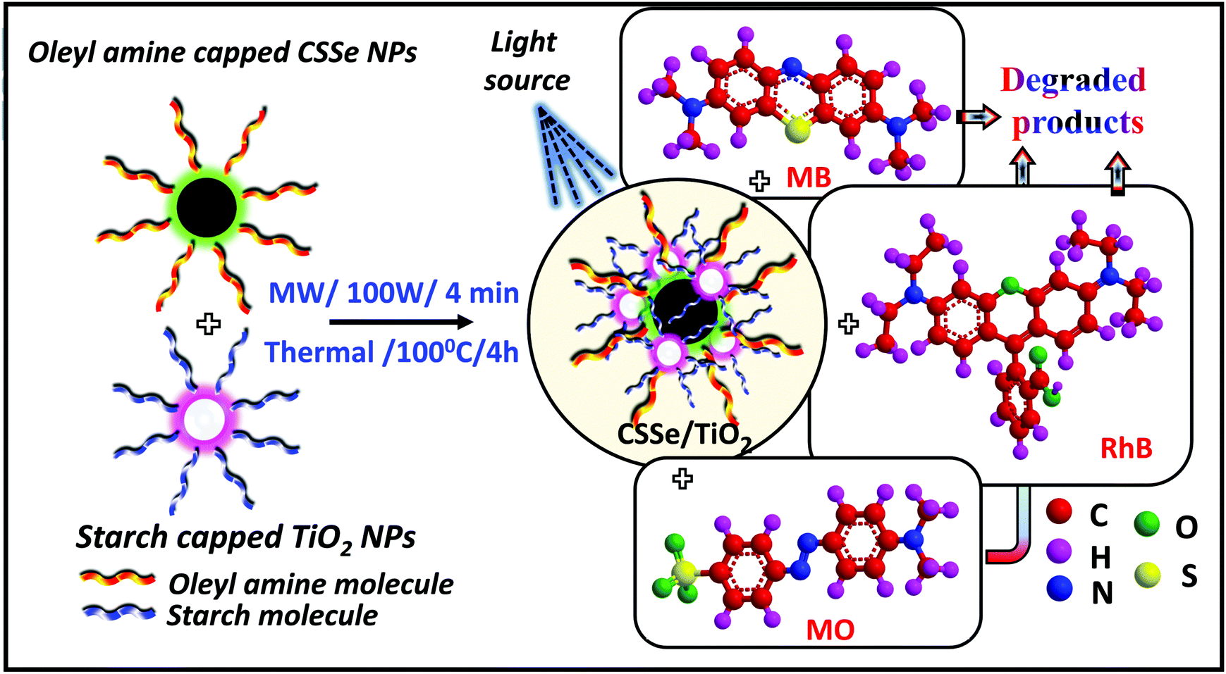 | ||
| Scheme 1 Process of CSSe/TiO2 nanohybrid formation and its utility as a photocatalyst for dye degradation. | ||
The change in the optical properties of the as-prepared nanohybrid photocatalyst can be studied by UV-visible spectroscopy. The as-prepared TiO2 NPs showed a peak at 323 nm, whereas CSSe NPs exhibited a broad absorption profile at about 700 nm with extended absorption in the NIR region (Fig. 1a). Effective hybridization by thermal and MW methods resulted in a change in the absorption profile. In case of the nano-hybrid material (CSSe/TiO2) obtained using the MW method (hereafter termed as CST-M) a broad absorption profile from 380 nm to 800 nm was observed with peak maxima of 472 nm (2.62 eV) (Fig. 1b). Similarly, another sample prepared by the thermal method (hereafter termed as CST-T) showed a broad peak at 423 nm (2.93 eV). Both profiles showed new absorption patterns for the hybrid material in the visible region, thus making it suitable for application as a visible-light photocatalyst.
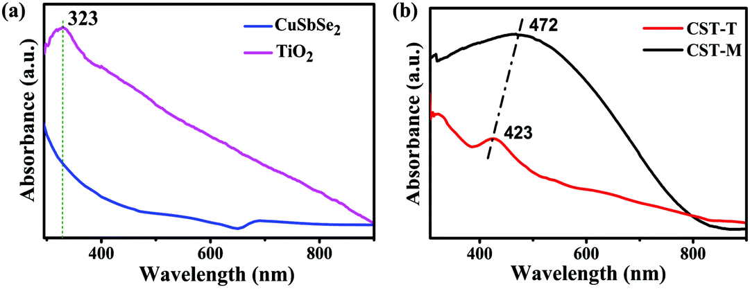 | ||
| Fig. 1 UV-visible absorption profiles of (a) CSSe and TiO2 NPs and (b) CST-M and CST-T. | ||
The XRD pattern of CSSe NPs showed major peaks at 2θ of 27.42°, 45.49° and 53.95°, confirming their orthorhombic crystal phase (Fig. 2, CSSe). The comparison of these peaks with the XRD results of nano-hybrid materials revealed the presence of other low-intensity peaks at 2θ of 26.51°, 36.29°, 48.78° and 53.38°. All these peaks were considered to be due to the presence of anatase TiO2.32 The low intensity obtained for TiO2 NPs in the XRD profile could be due to their low concentration in the nano-hybrid since the weight by weight ratio was 1![[thin space (1/6-em)]](https://www.rsc.org/images/entities/char_2009.gif) :0.25 (CSSe to TiO2). The presence of all the expected peaks for orthorhombic CSSe and anatase TiO2 confirmed effective coupling between these two without change in the crystal structure (Fig. 2, CST-M and CST-T). However, slight shift in 2θ values with broadening was observed in the case of both hybrid samples due to reduction in the crystalline nature mainly because of the presence of smaller nano-particles around CSSe. Similar observations have also been reported in literature for ZnS–CuInS2-alloyed nanostructures.21 Such an observation suggests only surface attachment between CSSe and TiO2 NPs without change in the crystal structure.
:0.25 (CSSe to TiO2). The presence of all the expected peaks for orthorhombic CSSe and anatase TiO2 confirmed effective coupling between these two without change in the crystal structure (Fig. 2, CST-M and CST-T). However, slight shift in 2θ values with broadening was observed in the case of both hybrid samples due to reduction in the crystalline nature mainly because of the presence of smaller nano-particles around CSSe. Similar observations have also been reported in literature for ZnS–CuInS2-alloyed nanostructures.21 Such an observation suggests only surface attachment between CSSe and TiO2 NPs without change in the crystal structure.
 | ||
| Fig. 2 XRD patterns of CSSe NPs, CST-M and CST-T nano-hybrid materials. | ||
SEM images of the hybrid materials are shown in Fig. 3(a) and (b), which demonstrate the spherical shape of the nanoparticles. The FESEM image of CST-M [Fig. 3(a)] shows a cluster of spherical nanoparticles, which form a network due to random surface attachment. In the case of CST-T [Fig. 3(b)], the formation of large globules with a rough surface is observed. The formation of large globules in this case can be due to agglomeration caused by excess heating for a longer duration. Even though CST-T exhibited agglomeration, the spherical shape of the nanoparticles could be easily recognized. EDS analysis of the nanohybrids revealed a near stoichiometric ratio between the elements (Fig. S1, ESI†). The higher percentage of oxygen could be due to the presence of starch, which was employed as a capping agent during the synthesis of TiO2 NPs.
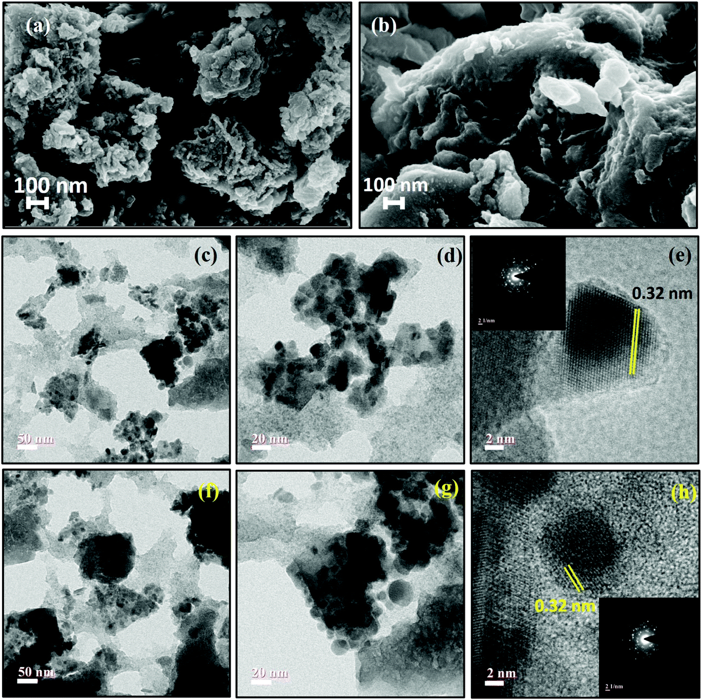 | ||
| Fig. 3 (a and b) FESEM images of CST-M and CST-T, (c–e) TEM images of CST-M and (f–h) TEM of CST-T. Insets of image (e) and image (h) are SAED patterns of CST-M and CST-T nanohybrid materials. | ||
TEM analysis of the as-prepared hybrid materials confirmed the presence of both TiO2 and CSSe NPs in a coupled state. The TEM images of CST-M [Fig. 3(c) and (d)] show large spherical CSSe NPs surrounded by smaller TiO2 NPs, forming a hybrid nanostructured material. HRTEM of sample CST-M [Fig. 3(e)] revealed lattice fringes with a spacing of 0.32 nm, which matched well with the values reported for the (013) crystal plane of CSSe NPs and the (110) crystal plane of TiO2. The inset of Fig. 3(e) shows the SAED pattern of CST-M with strong diffraction from the selected area, which confirms the crystallinity of the sample. Similarly, TEM images of CST-T show the presence of both NPs with spherical to oval morphology. Fig. 3(f) shows slight agglomeration of nanoparticles forming clusters of TiO2 and CSSe NPs. An enlarged image at a scale bar of 20 nm [Fig. 3(g)] shows the presence of small TiO2 NPs around CSSe NPs, confirming the surface attachment between the two. HRTEM images [Fig. 3(h)] reveal a similar observation as that for the CST-M sample. The inset of image (h) is the SAED pattern of CST-T and confirms the crystalline nature of the material.
The FTIR spectra show the presence of organic capping around the particles. Both samples (CST-M and CST-T) showed the presence of all expected functional groups [Fig. S2(a), ESI†]. Since oleyl amine and starch were employed as capping agents during the synthesis of CSSe and TiO2 NPs, vibrational peaks due to various functional groups such as NH2, CH, and C–O were observed in the FTIR spectra. We observed two peaks at 3311 cm−1 and 3239 cm−1 for CST-M and two peaks at 3302 cm−1 and 3205 cm−1 in the case of CST-T due to stretching vibrations of the NH2 group of oleyl amine.33 Asymmetric and symmetric C–H stretching peaks were obtained at 2918 cm−1 and 2842 cm−1 for CST-M and at 2922 cm−1 and 2851 cm−1 for CST-T.
Peaks due to NH2 and C–H bending were also observed for CST-M at 1538 cm−1 and 1429 cm−1, whereas similar stretching modes of vibration were observed at 1547 cm−1 and 1428 cm−1 in the case of CST-T. The C![[double bond, length as m-dash]](https://www.rsc.org/images/entities/char_e001.gif) C stretching frequency was observed at 1636 cm−1 in both samples. All these peaks confirmed the presence of oleyl amine and starch capping around CSSe and TiO2 NPs. However, the absence of OH stretching could be due to a very low concentration of starch remaining due to thermal as well as MW processing.
C stretching frequency was observed at 1636 cm−1 in both samples. All these peaks confirmed the presence of oleyl amine and starch capping around CSSe and TiO2 NPs. However, the absence of OH stretching could be due to a very low concentration of starch remaining due to thermal as well as MW processing.
Raman analysis of CST-M and CST-T revealed the presence of several broad peaks due to the vibrational modes of CSSe and TiO2 NPs [Fig. S2(b), ESI†]. Compound semiconductor CSSe NPs were expected to show Raman active modes of B3g, Ag and B2g at 140 cm−1, 154 cm−1, 210 cm−1 and 216 cm−1.34 Among these peaks, B3g and Ag overlapped and appeared at 142 cm−1. Broad peaks observed at 200 cm−1 and 216 cm−1 were considered to be due to the B2g vibrational mode of CSSe NPs. Furthermore, TiO2 NPs are known to exhibit peaks at 144 cm−1, 198 cm−1 and 398 cm−1 due to Eg and B1g vibrational changes.25,32 It was considered that the Eg vibrational peak of TiO2 overlapped with the broad intense B3g vibrational peak of CSSe NPs at 142 cm−1. Other peaks due to Eg and B1g modes of vibrations were observed at 198 cm−1 and 398 cm−1 for TiO2 NPs. Therefore, the presence of all the expected Raman-active peaks for CST-M and CST-T confirmed their purity and effective hybridization.
The average particle size distribution of the as-prepared nano-hybrid materials dispersed in DMF was evaluated by a particle size analyzer working on the principle of dynamic light scattering. The sample CST-M showed average particle size distribution of 17 nm, whereas CST-T exhibited average size of 19 nm (Fig. S3, ESI†). Both samples exhibited wide particle size distribution in the range from 2 to 35 nm, which was due to the presence of varied sizes of CSSe and TiO2 NPs in the nano-hybrid. Marginally wider particle size distribution of the nano-hybrid prepared using the thermal method than that of the nano-hybrid obtained using the MW method could be due to the overgrowth of particles promoted by prolonged heating during synthesis.
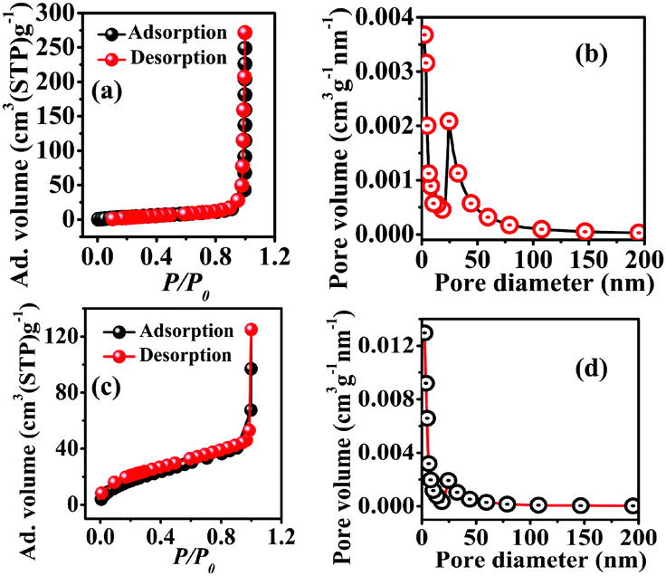
Brunauer–Emmett–Teller (BET) and Barrett–Joyner–Halenda (BJH) analyses of both samples were carried out to obtain their specific surface area as well as porosity. The N2 adsorption and desorption of CST-M and CST-T showed a type III adsorption isotherm according to the IUPAC classification, corresponding to the microporous nature of the materials [Fig. 4(a) and (c)]. The adsorption on the microporous material according to a type III isotherm suggested weak interaction between the adsorbent and the adsorbate. Both samples showed H1 type adsorption hysteresis, indicating the presence of agglomerates or compactly arranged nanoparticles. The surface areas obtained for CST-M and CST-T are presented in Table 1.
 | ||
| Fig. 4 BET adsorption–desorption isotherms (a and c) and pore size distribution (b and d) for CST-M and CST-T. | ||
| BET results | |||
|---|---|---|---|
| Sample | Constant ‘C’ | Monolayer adsorption volume (Vm) (cm3 g−1) | BET surface area (m2 g−1) |
| CST-M | 15.523 | 3.2573 | 14.17 |
| CST-T | 32.806 | 14.725 | 64.089 |
| BJH results | |||
|---|---|---|---|
| Sample | Surface area of pores (m2 g−1) | Pore volume (cm3 g−1) | Mean pore diameter (nm) |
| CST-M | 22.589 | 0.067749 | 18.27 |
| CST-T | 59.261 | 0.097191 | 06.31 |
CST-M and CST-T showed mean pore size diameters of 18.27 nm and 06.31 nm, respectively [Fig. 4(b) and (d)]. The BJH plots of both samples showed agglomerated particles, resulting in pores with diameter as large as 60–70 nm with random pore size distribution. The total pore volumes were found to be 0.0677 cm3 g−1 and 0.0971 cm3 g−1 for CST-M and CST-T, respectively. Table 1 presents the BET and BJH results.
XPS analysis of the sample synthesized by the microwave method (CST-M) showed the presence of all elements with the expected binding energy values and oxidation states. A full scan of a typical sample, CST-M, revealed the presence of all elements, i.e., Cu, Sb, Se, Ti, O and C [Fig. 5(a)]. HRXPS of copper showed the presence of two peaks at binding energies of 935.5 eV and 955.2 eV with peak splitting of about 19.7 eV, which suggested the presence of monovalent copper in the sample35 [Fig. 5(b)]; these peaks corresponded to the 2p3/2 and 2p1/2 states of Cu+. The monovalent nature of copper could be due to the reduction of Cu2+ to Cu+ during the reaction. Antimony showed two peaks at 532.8 eV and 542.3 eV, corresponding to the 3d5/2 and 3d3/2 states of trivalent antimony (Sb3+) [Fig. 5(c)]. A peak observed at 56.2 eV [Fig. 5(d)] confirmed the presence of the 3d state of selenium with −2 oxidation state (Se2−). HRXPS of titanium revealed two different peaks at 459.96 eV and 465.3 eV, which suggested the presence of 2p3/2 and 2p1/2 states of tetravalent titanium (Ti4+) [Fig. 5(e)]. Other elements such as oxygen and carbon showed peaks at 532.84 eV and 286.0 eV for 1s states [Fig. 5(f) and (g)]. The presence of a single peak for oxygen rules out the involvement of oxygen from the lattice (Ti–O), surfactant (C–O) and adsorbed moisture (O–H).25
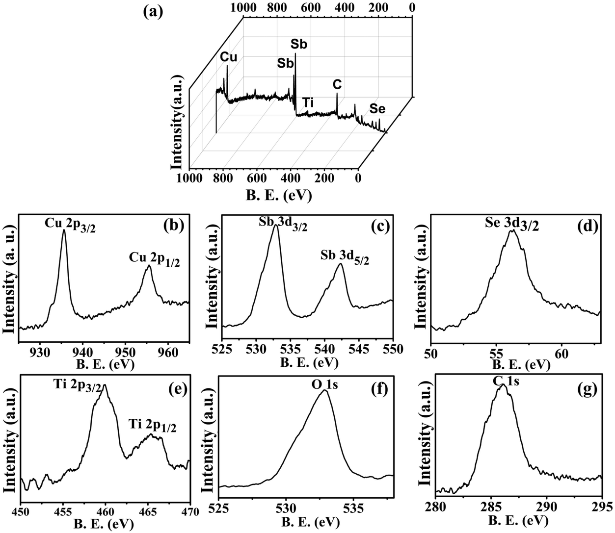 | ||
| Fig. 5 XPS analysis of CSSe/TiO2 prepared using the MW method (CST-M). | ||
3.1. Photocatalytic degradation of organic dyes
The degradation of organic dyes basically depends on the generation of superoxide and hydroxyl radicals upon light irradiation over an aqueous solution in the presence of a photocatalyst. The photocatalyst plays a pivotal role as it provides charge carriers for the effective production of essential radicals as well as surface area for the adsorption of dyes. The photocatalyst is considered as the most important material in the degradation process since the production of radicals is completely dependent on a low recombination rate of the charge carriers36 and therefore, the choice of the photocatalyst is an important aspect.In the present study, the CSSe/TiO2 nano-hybrid containing wide- and small-band-gap semiconductors can help reduce the rate of recombination and thus enhance the rate of radical formation for efficient degradation of organic dyes. Irradiation of such a hybrid system by light of the desired wavelength leads to the generation of electron–hole pairs. Electrons from the conduction band of CSSe are probably transferred to the conduction band of TiO2 because of the lower energy conduction band; they are further utilized for the generation of hydroxyl radicals. On the other side, holes are considered to be responsible for the oxidation of water and they eventually form hydroxyl radicals. Therefore, the degradation of organic dyes can occur due to the attack of such in situ-generated hydroxyl radicals. Overall, the reaction sequences are depicted in Scheme 2.
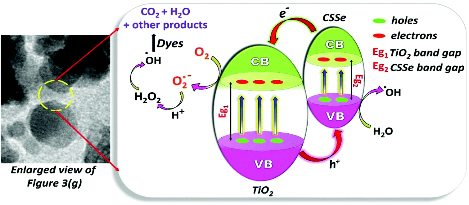 | ||
| Scheme 2 The process highlighting the formation of reactive radicals for the degradation of organic dyes. | ||
Solutions of three different dyes MB, MO and RhB (100 ppm) were used for the degradation study under long UV-A irradiation (365 nm). The UV-visible absorption spectra of the as-prepared nano-photocatalysts showed absorption in the visible region and therefore, a UV-A source was chosen for the study. The degradation of the dyes was monitored by UV-visible absorption spectroscopy at fixed time intervals. A known volume fraction was withdrawn and monitored for any changes in the absorption intensity of the dyes. The continuous decrease in the absorption maxima with respect to time corresponded to the degradation of dyes. In the present case, degradation reactions were monitored for five hours with time intervals of 30 min. The decrease in the absorption maxima after continuous irradiation with respect to the initial (zero time) absorption was considered as a change in the concentration of the dye due to its degradation. Therefore, the percentage degradation in this case can be obtained by employing the following equation:19,33
 | (1) |
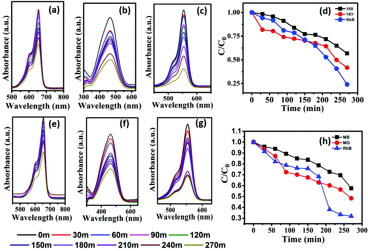 | ||
| Fig. 6 Monitoring the degradation of MB (a and e), MO (b and f) and RhB (c and g) using photocatalysts CST-M and CST-T, respectively. (d and h) C/C0versus time plots of degradation of MB, MO and RhB. | ||
| Dye | MB | MO | RhB | |||
|---|---|---|---|---|---|---|
| Cat. | CST-M | CST-T | CST-M | CST-T | CST-M | CST-T |
| % eff. | 43.14 | 42.72 | 58.26 | 51.70 | 75.93 | 68.18 |
| k (min−1) | 0.0652 | 0.0718 | 0.0708 | 0.0795 | 0.0552 | 0.0672 |
| E a (J mol−1) | 6810 | 6569 | 6605 | 6313 | 7224 | 6735 |
The highest degradation efficiency of 75.93% was obtained against RhB using the CST-M photocatalyst, whereas the lowest value was 42.72% in the case of MB for CST-T. The more effective degradation of RhB than that of MB and MO could be due to its effective surface adsorption driven by the presence of –COOH functional groups and a large surface area and also probably due to low recombination rate of the charge carriers of as-prepared photocatalysts. The comparison of the present findings with degradation carried out using TiO2 as a photocatalyst under similar conditions32 emphasizes that the combination of CSSe and TiO2 is effective against MO and RhB. The degradation efficiency of TiO2 against RhB was 54.85%, whereas CSSe/TiO2 prepared by the MW technique showed 75.93% degradation of RhB under similar conditions. The increase in the degradation efficiency by 21.08% revealed the effectiveness of the hybrid material via separation of the charge carriers and its utilization for redox reactions.
Fig. 6(d) and (h) show C/C0versus time plots for the degradation of dyes using CST-M and CST-T, respectively, which reveals continuous decrease in concentration with respect to time. For better understanding and clarity, the degradation process was studied by first order kinetics and rate constant values were estimated using the following equations:19,32
| C = C0e−kt | (2) |
 | (3) |
 | (4) |
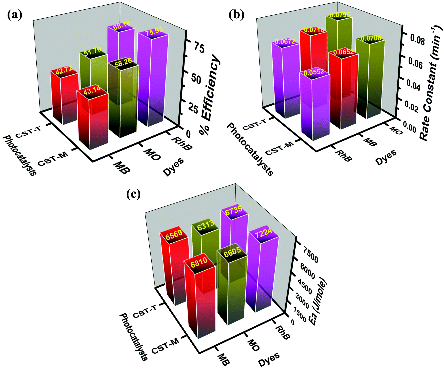 | ||
| Fig. 7 Comparative analysis of the degradation efficiency, rate constant and energy of activation values obtained from degradation study. | ||
3.2. Recycling study of CSSe/TiO2
The photostability and chemical stability of the as-prepared photocatalyst were evaluated by a recycling study. For the recycling study, the photocatalyst CST-M was employed against RhB. CST-M was used initially for the degradation of RhB; after completion of the reaction, CST-M was recollected by centrifugation at 5500 rpm for 20 min and washed several times to ensure the removal of the adsorbed dye from CST-M. The CST-M photocatalyst was reused for the degradation of RhB and the same procedure was repeated five times. A continuous decrease in the absorption maxima with respect to time corresponded to the degradation of RhB [Fig. 8(a)]. The degradation of RhB was found to be nearly constant since the same photocatalyst under similar conditions was employed. The C/C0vs. time plot for each cycle represents the effective degradation of RhB during each cycle [Fig. 8(b)]. The degradation efficiency calculated for each cycle demonstrated that there was not much loss even after the fifth cycle of the degradation study. The first cycle showed 72.23% degradation efficiency, which was found to slightly decrease after each cycle. The slight decrease in degradation efficiency was attributed to the decrease in the adsorbing power of the photocatalyst after each cycle because washing after each cycle to remove the adsorbed dye failed to completely remove all the adsorbed dye and resulted in decrease in the degradation efficiency after each cycle. The degradation efficiency, rate constant, energy of activation and percentage loss observed after each cycle are given in Table 3. The rate of degradation of RhB and the energy of activation were found to be almost constant. Therefore, the CSSe/TiO2 photocatalysts can be employed for efficient and effective degradation of dyes even after five cycles. The present findings, therefore, emphasize the photostability, chemical stability and effectiveness of the CSSe/TiO2 photocatalyst for degradation of different organic dyes.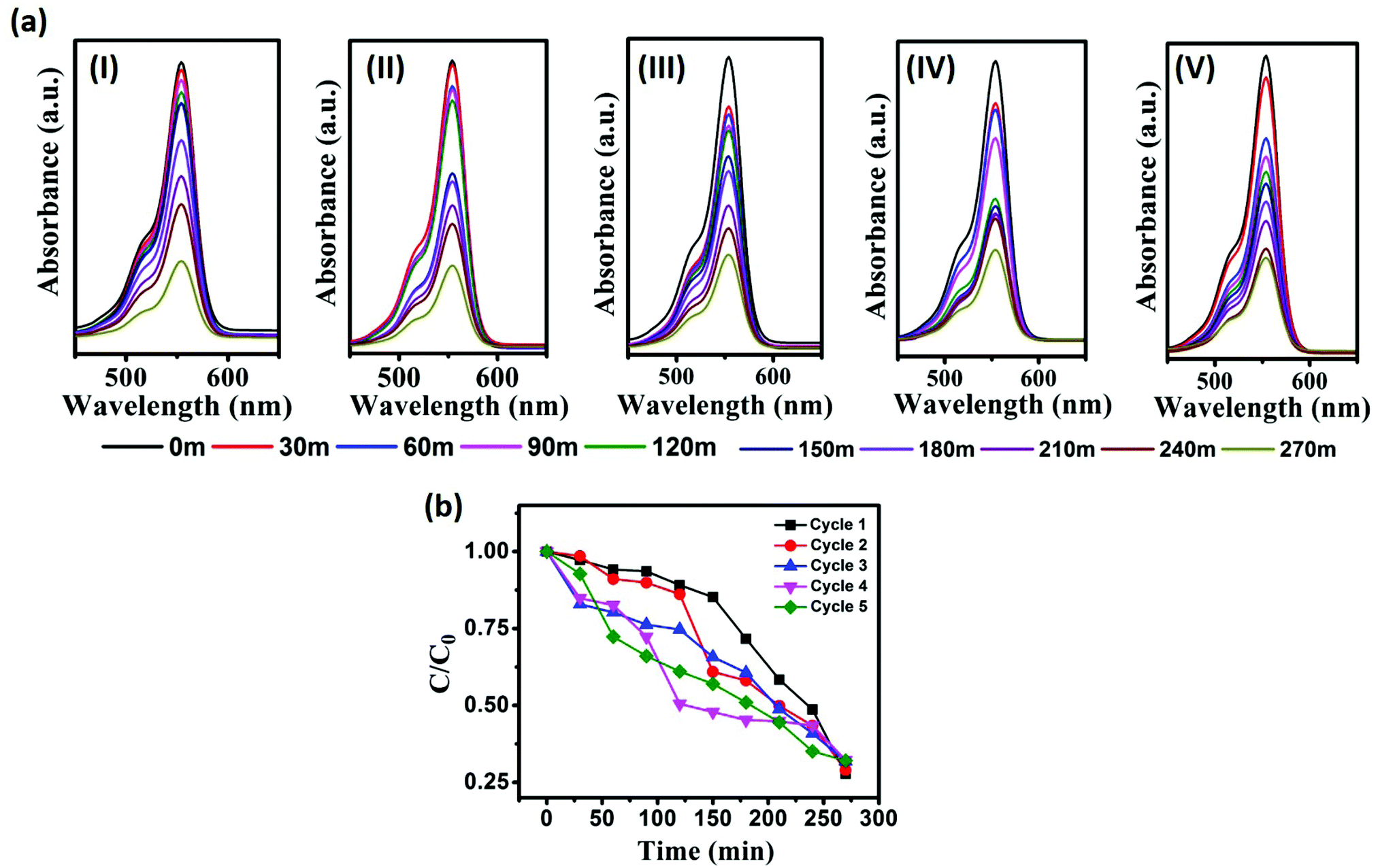 | ||
| Fig. 8 (a) Monitoring of RhB degradation using the recycled photocatalyst CST-M; (b) C/C0vs. time plot for degradation of RhB using CST-M. | ||
| Attempt | Deg. eff. (%) | % loss in eff. | Rate constant (min−1) | E a (J mol−1) |
|---|---|---|---|---|
| 1 | 72.23 | 0.0 | 0.06189 | 6940.9 |
| 2 | 71.03 | 1.20 | 0.06175 | 6946.5 |
| 3 | 68.15 | 4.08 | 0.05822 | 7093.4 |
| 4 | 67.78 | 4.45 | 0.05935 | 7045.4 |
| 5 | 67.90 | 4.33 | 0.06065 | 6991.4 |
The present findings highlighted the applicability of the novel type-II heterojunction photocatalyst (CSSe/TiO2) for effective degradation of various organic dyes. The combination of two semiconductors possessing small and wide band gaps was shown to successfully result in a photocatalyst under UV-A light. The combination of two such semiconductors helped to reduce the recombination rate and thus enhanced the photocatalytic degradation. The comparison of the present findings with those reported in literature revealed the absence of any report on the applicability of CuSbSe2 NPs or their hybrid as a photocatalyst for the degradation of MB, MO and RhB. However, there are some reports on the use of other ternary metal selenides containing hybrids such as CuInSe2/TiO2 nanotubes, CuInS2/TiO2, CuInSe2/ZnO and CuInS2/ZnO for the degradation of various organic dyes.19–23
Fig. 9 represents the comparison of the present study with our previous study. The degradation carried out using a hybrid composed of ternary metal selenide showed varied performances and amongst all results, the results obtained in the present study stand out. The composition of the individual components in the hybrid is mentioned on the respective bars. Different factors such as the source of light, its intensity and the type of dye are responsible for effective degradation. Comparison of experimental results with those of literature for the degradation of dyes under different experimental conditions is difficult. Therefore, the results obtained in the present study were compared with our previous results, where the previous study was carried out under similar experimental conditions. The comparative analysis suggested better performance of CuSbSe2/TiO2 than those of AgInSe2/TiO2, CuInSe2/TiO2 and AgInSe2/Ag2Se nano-hybrids, especially against RhB. Therefore, this emphasizes the applicability of ternary metal selenides in photocatalysis; however, CuSbSe2/TiO2 showed better performance against RhB and the present finding is a first of its kind. Therefore, the present outcome is of great importance, highlighting the effectiveness of the CuSbSe2/TiO2 hybrid as a photocatalyst.
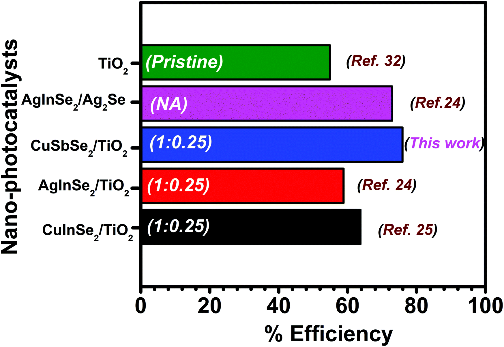 | ||
| Fig. 9 Comparison of the degradation efficiency against RhB reported in literature with the present findings. The values presented on the bars are ratios between two components of the hybrid. | ||
4. Conclusion
The combination of CuSbSe2 and TiO2 NPs by thermal and microwave methods resulted in nano-hybrids having different properties than their parent semiconductors. The remarkable optical properties of the as-prepared hybrids encouraged us to employ such nano-hybrid materials for photocatalytic dye degradation studies. For the degradation study, three different dyes MB, MO and RhB were selected to test the effectiveness of the photocatalysts. The degradation of the three dyes was carried out under long UV-A irradiation and monitored by UV-visible spectroscopy. According to the degradation results, it was observed that the degradation efficiency was higher against RhB (75%) using the CST-M photocatalyst as compared to that against MB and MO. The comparison of degradation results with those of previously synthesized CuInSe2/TiO2 and AgInSe2/TiO2 revealed a higher degradation percentage of RhB using the current photocatalyst, which confirmed its effectiveness against RhB. The comparison with the photocatalytic activity of parent semiconductors (CSSe and TiO2 NPs) also suggested the robust nature of the nano-hybrid and resulted in better performance. The rate of reaction was found to be enhanced relative to that of the parent semiconductors. The recycling study highlighted the effective reuse of the as-prepared photocatalyst without significant loss in the degradation efficiency. Overall, it can be stated that this novel type-II heterojunction photocatalyst is suitable for the degradation of organic dyes and can be further tested as a photocatalyst for H2 generation by water splitting.Conflicts of interest
Authors declare no conflict of interest.Acknowledgements
Authors thank Vice-Chancellor, Defence Institute of Advanced Technology (DIAT), Pune for permission and for a Senior Research Fellowship (SRF) to ASK. Anuraj gratefully acknowledges his college teachers namely Mr R. B. Nikam, Dr D. V. Jagtap and Dr Sande for their constant motivation, encouragement and advice to pursue research oriented higher studies in Chemistry/Chemical Sciences.References
- Y. Z. Chen, N. Li, Y. Zhang and L. D. Zhang, J. Colloid Interface Sci., 2014, 422, 9–15 CrossRef CAS PubMed.
- L. R. Maryin, G. Andrés, R. Z. Hugo, M. T. S. Adrián, M. M. Luis and H. R. Jose, Appl. Catal., B, 2014, 146, 192–200 CrossRef.
- L. Yue, G. Zhigang, C. Hongbing, M. Lu, C. Jia, Z. Jie, P. Nan and W. Xiaoping, Eur. J. Inorg. Chem., 2012, 4439–4444 Search PubMed.
- R. Daghrir, P. Drogui and D. Robert, Ind. Eng. Chem. Res., 2013, 52, 3581–3599 CrossRef CAS.
- N. Her, J. S. Park and Y. Yoon, Chem. Eng. J., 2011, 166, 184 CrossRef CAS.
- C. A. Martinez-Huitle and S. Ferro, Chem. Soc. Rev., 2006, 35, 1324–1340 RSC.
- (a) Y. Jin, H. Zhang, C. Song, L. Wang, Q. Lu and F. Gao, Sci. Rep., 2016, 6, 29997–30004 CrossRef CAS PubMed; (b) J. Gröttrup, F. Schütt, D. Smazna, O. Lupan, R. Adelung and Y. K. Mishra, Ceram. Int., 2017, 43, 14915–14922 CrossRef; (c) Y. K. Mishra and R. Adelung, Mater. Today, 2018, 21, 631–651 CrossRef CAS; (d) T. B. Demille, R. A. Hughes, A. S. Preston, R. Adelung, Y. K. Mishra and S. Neretina, Front. Chem., 2018, 6, 411 CrossRef PubMed; (e) M. Sharma, M. Joshi, S. Nigam, S. Shree, D. K. Avasthi, R. Adelung, S. K. Srivastava and Y. K. Mishra, Chem. Eng. J., 2019, 358, 540–551 CrossRef CAS.
- L.-W. Zhang, Y.-J. Wang, H.-Y. Cheng, W.-Q. Yao and Y.-F. Zhu, Adv. Mater., 2009, 21, 1286–1290 CrossRef CAS.
- L. Guodong, J. Shulin, Y. Liangliang, X. Guoping, F. Guangtao and Y. Changhui, J. Appl. Phys., 2011, 109, 063103 CrossRef.
- C.-C. Shen, Q. Zhu, Z.-W. Zhao, T. Wen, X. Wang and A.-W. Xu, J. Mater. Chem. A, 2015, 3, 14661–14668 RSC.
- H. Wang, L. Zhang, Z. Chen, J. Hu, S. Li, Z. Wang, J. Liu and X. Wang, Chem. Soc. Rev., 2014, 43, 5234–5244 RSC.
- J. C. Yu, J. G. Yu, K. W. Ho, Z. T. Jiang and L. Z. Zhang, Chem. Mater., 2002, 14, 3808–3816 CrossRef CAS.
- (a) H. Li, Y. Zhou, W. Tu, J. Ye and Z. Zou, Adv. Funct. Mater., 2015, 25, 998 CrossRef CAS; (b) S. Sun, Nanoscale, 2015, 7, 10850–10882 RSC.
- J. L. White, M. F. Baruch, J. E. Pander III, Y. Hu, I. C. Fortmeyer, J. E. Park, T. Zhang, K. Liao, J. Gu and Y. Yan, Chem. Rev., 2015, 115, 12888–12935 CrossRef CAS PubMed.
- (a) D. Aldakov, A. Lefrançois and P. Reiss, J. Mater. Chem. C, 2013, 1, 3756–3776 RSC; (b) B. Chen, N. Pradhan and H. Zhong, J. Phys. Chem. Lett., 2018, 9, 435–445 CrossRef CAS PubMed; (c) D. R. Michelle and H. Ming-Yong, Acc. Chem. Res., 2016, 49, 511–519 CrossRef PubMed; (d) C. Coughlan, M. Ibanez, O. Dobrozhan, A. Singh, A. Cabot and K. M. Ryan, Chem. Rev., 2017, 117, 5865–6109 CrossRef CAS PubMed; (e) F. Meinardi, H. McDaniel, F. Carulli, A. Colombo, K. A. Velizhanin, N. S. Makarov, R. Simonutti, V. I. Klimov and S. Brovelli, Nat. Nanotechnol., 2015, 10, 878–885 CrossRef CAS PubMed.
- B. Zhang, M.-L. Feng, J. Li, Q. Hu, X. H. Qi and X.-Y. Huang, Cryst. Growth Des., 2017, 17, 1235–1244 CrossRef CAS.
- Z. Chen, D. Li, W. Zhang, Y. Shao, T. Chen, M. Sun and X. Fu, J. Phys. Chem. C, 2009, 113, 4433–4440 CrossRef CAS.
- K.-Y. Wang, L.-J. Zhou, M.-L. Fenga and X.-Y. Huang, Dalton Trans., 2012, 41, 6689–6695 RSC.
- F. Shen, W. Que, Y. Liao and X. Yin, Ind. Eng. Chem. Res., 2011, 50, 9131–9137 CrossRef CAS.
- M. Bagheri, A. R. Mahjoub and B. Mehri, RSC Adv., 2014, 4, 21757–21764 RSC.
- W. Zhang and X. Zhong, Inorg. Chem., 2011, 50, 4065–4072 CrossRef CAS PubMed.
- F. Shen, W. Que, Y. He, Y. Yuan, X. Yin and G. Wang, ACS Appl. Mater. Interfaces, 2012, 4, 4087–4092 CrossRef CAS PubMed.
- Y. Liao, H. Zhang, Z. Zhong, L. Jia, F. Bai, J. Li, P. Zhong, H. Chen and J. Zhang, ACS Appl. Mater. Interfaces, 2013, 5, 11022–11028 CrossRef CAS PubMed.
- A. S. Kshirsagar and P. K. Khanna, Inorg. Chem. Front., 2018, 5, 2242–2256 RSC.
- A. S. Kshirsagar, A. Gautam and P. K. Khanna, J. Photochem. Photobiol., A, 2017, 349, 73–90 CrossRef CAS.
- (a) D. Tang, J. Yang, F. Liu, Y. Lai, J. Li and Y. Liu, Electrochim. Acta, 2012, 76, 480–486 CrossRef CAS; (b) C. Yang, Y. Wang, S. Li, D. Wan and F. Huang, J. Mater. Sci., 2012, 47, 7085–7089 CrossRef CAS.
- D. Zhang, J. Yang, Q. Jiang, L. Fu, Y. Xiao, Y. Luo and Z. Zhou, J. Mater. Chem. A, 2016, 4, 4188–4193 RSC.
- T.-R. Wei, C.-F. Wu, W. Sun, Y. Pan and J.-F. Li, RSC Adv., 2015, 5, 42848–42854 RSC.
- (a) A. S. Kshirsagar and P. K. Khanna, ChemistrySelect, 2018, 3, 2854–2866 CrossRef CAS; (b) I. Tiginyanu, T. Braniste, D. Smazna, M. Deng, F. Schütt, A. Schuchardt, M. A. Stevens-Kalceff, S. Raevschi, U. Schürmann, L. Kienle, N. M. Pugno, Y. K. Mishra and R. Adelung, Nano Energy, 2019, 56, 759–769 CrossRef CAS.
- J. Schneider, M. Matsuoka, M. Takeuchi, J. Zhang, Y. Horiuchi, M. Anpo and D. W. Bahnemann, Chem. Rev., 2014, 114, 9919–9986 CrossRef CAS PubMed.
- H. Meir and E. Voigt, Tetrahedron, 1972, 28, 187–198 CrossRef.
- A. Gautam, A. Kshirsagar, R. Biswas, S. Banerjee and P. K. Khanna, RSC Adv., 2016, 6, 2746–2759 RSC.
- S. Mourdikoudis and L. M. Liz-Marzan, Chem. Mater., 2013, 25, 1465–1476 CrossRef CAS.
- (a) K. Samanta, N. Gupta, H. Kaur, L. Sharma, S. D. Pandey, J. Singh, T. D. Senguttuvan, N. D. Sharma and A. K. Bandyopadhyay, Mater. Chem. Phys., 2015, 151, 99–104 CrossRef CAS; (b) J. Baker, R. S. Kumar, D. Sneed, A. Connolly, Y. Zhang, N. Velisavljevic, J. Paladugu, M. Pravica, C. Chen, A. Cornelius and Y. Zhao, J. Alloys Compd., 2015, 643, 186–194 CrossRef CAS.
- J.-J. Wang, Y.-Q. Wang, F.-F. Cao, Y.-G. Guo and L.-J. Wan, J. Am. Chem. Soc., 2010, 132, 12218–12221 CrossRef CAS PubMed.
- L. Nieab and Q. Zhang, Inorg. Chem. Front., 2017, 4, 1953–1962 RSC.
- (a) C. Chen, J. Liu, P. Liu and B. Yu, Adv. Chem. Eng. Sci., 2011, 1, 9–14 CrossRef CAS; (b) M. Menzinger and R. Wolfgang, Angew. Chem., 1969, 6, 438–444 CrossRef.
Footnote |
| † Electronic supplementary information (ESI) available. See DOI: 10.1039/c8qm00537k |
| This journal is © the Partner Organisations 2019 |