
Chiral zeolite beta: structure, synthesis, and application
Tingting
Lu
ab,
Wenfu
Yan
 *a and
Ruren
Xu
a
*a and
Ruren
Xu
a
aState Key Laboratory of Inorganic Synthesis and Preparative Chemistry, College of Chemistry, Jilin University, Changchun 130012, P. R. China. E-mail: yanw@jlu.edu.cn
bInstitute of Catalysis for Energy and Environment, College of Chemistry and Chemical Engineering, Shenyang Normal University, Shenyang 110034, P. R. China
First published on 11th June 2019
Abstract
Zeolite beta is an intergrowth of two or three polymorphs, including chiral polymorph-A, achiral polymorph-B, and polymorph-C. Chiral polymorph-A of zeolite beta is highly desired because of its potential applications in enantioseparation and asymmetric catalysis. However, it is still impossible to obtain the pure polymorph-A of zeolite beta. This review comprehensively summarizes and evaluates the recent progress in the studies of chiral zeolite beta. An insight into the intergrowth structure of zeolite beta revealing the chiral feature of polymorph-A is provided. The synthesis of chiral polymorph-A enriched zeolite beta and the corresponding chiral applications are discussed. The unsolved challenges are outlined and the areas for future exploration in the synthesis of polymorph-A of zeolite beta are suggested.
 Tingting Lu | Tingting Lu obtained her Ph.D. degree from Jilin University in 2018. She is currently a lecturer in the College of Chemistry and Chemical Engineering at Shenyang Normal University. Her research interest is in the designed syntheses of zeolites and their applications in catalysis. |
 Wenfu Yan | Wenfu Yan received his Ph.D. degree from Jilin University in 2002 and worked as a post-doctoral fellow at Oak Ridge National Laboratory during 2002–2005. He has been a full professor in the College of Chemistry, Jilin University since 2008. He was awarded the Excellent Young Scientists Fund of the National Natural Science Foundation of China in 2012. His main research interest lies in the synthesis and applications of zeolitic materials. He serves as the Vice President and Secretary General of the Chinese Zeolite Association and the Editorial Board Member for Scientific Reports. |
 Ruren Xu | Ruren Xu obtained his B.S. degree from National Shanghai Jiaotong University in 1952 and worked at Fu Dan University and Hamburg University. He has been a professor in the Chemistry Department, Jilin University since 1979. His research interest is in the molecular engineering of zeolite and porous materials. He is an academician of the Chinese Academy of Sciences and the Third World Academy of Sciences. |
1. Introduction
Zeolites are crystalline microporous materials formed by corner-sharing TO4 (T = Si or Al) tetrahedra, which have the periodic one-to-three dimensional frameworks, unique porous structure, and fine thermal and chemical stability.1–3 They have found widespread applications in many industrial fields such as catalysis, adsorption, separation, and ion exchange. Chiral zeolites generally crystallize in any of the 65 Sohncke space groups, which lack any improper symmetry elements (inversion, reflection, glide, or roto-inversion).4–7 The intrinsic chirality of chiral zeolites is independent of their chemical elements. Chiral zeolites can combine both shape selectivity and enantioselectivity, which are desirable for chiral adsorption, enantioseparation, and asymmetric catalysis.8,9 Therefore, the search for and development of chiral zeolites with excellent performance remain significant.Chirality is a fundamental property of the natural world, but rare in inorganic porous materials, especially in zeolites.10,11 The number of chiral zeolites is very limited. Of the 245 zeolitic framework types known up to now (May 2019),12 only 8 show inherently chiral structures, including *BEA,13–15 CZP,16 GOO,17 -ITV,18 JRY,19 LTJ,20 OSO,21 and STW22 (listed in Table 1). Zeolite beta with one of its polymorphs (*BEA) was first discovered to be chiral, which inspired researchers to focus on the synthesis of this type of material.
| Framework code | Type material | Space groupa | Channel dimensionality | Maximal ring size | Elemental composition | Ref. |
|---|---|---|---|---|---|---|
| a Represents the space group of the framework structure, which might be different with the space group of corresponding type material. | ||||||
| *BEA | Beta polymorph-A | P4122, P4322 | 3 | 12 | Al, Si | 13–15 |
| CZP | Chiral zincophosphate | P6122, P6522 | 1 | 12 | Zn, P | 16 |
| GOO | Goosecreekite | C2221 | 3 | 8 | Al, Si | 17 |
| -ITV | ITQ-37 | P4132, P4332 | 3 | 30 | Ge, Si | 18 |
| JRY | CoAPO-CJ40 | I212121 | 1 | 10 | Co, Al, P | 19 |
| LTJ | Linde Type J | P41212 | 3 | 8 | Al, Si | 20 |
| OSO | OSB-1 | P6222, P6422 | 3 | 14 | Be, Si | 21 |
| STW | SU-32 | P6122, P6522 | 3 | 10 | Ge, Si | 22 |
Initially, in 1967, large-pore high-silica zeolite beta was first synthesized by Mobil Oil Corporation from a basic reaction mixture containing tetraethylammonium ions and was described as a useful adsorbent and highly active catalyst.23 The sorption and catalytic data indicate that zeolite beta could possess a 3-dimensional (3D) 12-membered ring pore structural characteristic. However, the powder X-ray diffraction (XRD) pattern of zeolite beta comprises both sharp and broad diffraction peaks, suggesting that structural disorder pervades the framework. The complex structure of zeolite beta makes it difficult to determine by conventional techniques even when large single crystals were available. Until 1988, more than twenty years after the first synthesis, Newsam et al. and Higgins et al. independently proposed the model of the structure of zeolite beta by combining the methods of high-resolution electron microscopy, electron diffraction, computer-assisted modelling, distance least-squares refinement, and powder pattern simulation.13–15 Structural elucidation shows that zeolite beta is an intergrowth of several distinct but closely related polymorphs, including chiral polymorph-A, achiral polymorph-B and polymorph-C.
After determining the structure of zeolite beta, many efforts have been devoted to the selective synthesis of its pure polymorph,24–26 especially chiral polymorph-A. Zeolite beta has been demonstrated to be industrially important in several hydrocarbon conversion reactions, including cracking,27,28 hydrocracking,29 alkylation,30,31 acylation,32,33 isomerization,34,35 and biomass conversion.36 Chiral zeolite beta with special chiral structure is promising to be of great value in chiral fields. This review is dedicated to this important material, chiral zeolite beta, presenting an effort to comprehensively evaluate the development, in order to promote the future breakthroughs in this field, ranging from asymmetric catalysis to enantioseparation science to the synthesis of enantiomerically pure drugs, and more.
2. Structure of chiral zeolite beta
Zeolite beta is one of the most complex materials and is of great importance in the zeolite family. The intergrowth structure of zeolite beta was first determined by Newsam et al. and Higgins et al. independently.13–15 Here, we will describe the framework structure of zeolite beta and illustrate the chiral structural features of polymorph-A. A good understanding of the chiral structure is central to the synthesis and application of chiral zeolite beta.2.1 Building model of ordered polymorphs
Zeolite beta is a typical stacking-fault intergrowth structure of several distinct but closely related polymorphs.37 These polymorphs are built from an identical centrosymmetric layer using different stacking sequences. The centrosymmetric layer is formed by the expansion of a secondary building unit (Fig. 1a) that consists of 16 T-atoms in the plane along two directions. The top view and side view of the centrosymmetric 2-dimensional (2D) building layer that consists of a 12-membered ring structure is shown in Fig. 1b and c, respectively.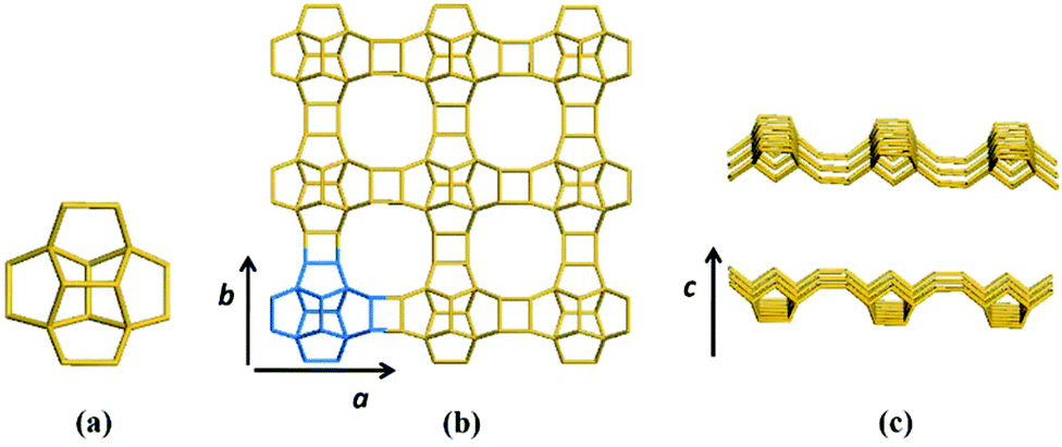 | ||
| Fig. 1 Secondary building unit (a) and centrosymmetric layer (b: top view, c: side view) of zeolite beta. | ||
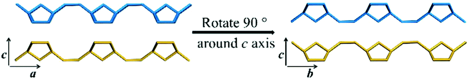
Structurally, the adjacent building layer could be obtained by a 90° rotation of the topologically identical layer around the c axis perpendicular to its plane direction. Since the layer is tetragonal, the view along the a axis is highly similar to that along the b axis, as shown in Fig. 2.
 | ||
| Fig. 2 The associations of the adjacent building layers in zeolite beta. | ||
In order to satisfy the chemical characteristics of zeolite, there are three translation modes between adjacent layers that could ensure effective chemical bond connectivity:
(1) The upper layer is shifted by 0 period along the a axis or b axis direction relative to the lower layer, that is, there is no translation, as shown in Fig. 3a.
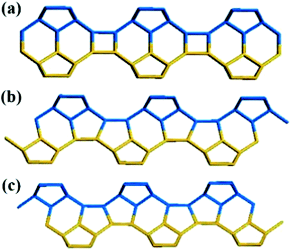 | ||
| Fig. 3 Three translation modes between adjacent building layers. | ||
(2) The upper layer is shifted by +1/3 period along the a axis or b axis direction relative to the lower layer, as shown in Fig. 3b.
(3) The upper layer is shifted by −1/3 period along the a axis or b axis direction relative to the lower layer, as shown in Fig. 3c.
The two adjacent layers could be effectively interconnected through the three ways mentioned above. However, if there are many layers to be connected, even a 2D plane can have an infinite number of different stacking sequences. Zeolite crystals have periodic structure, and we just consider the simple periodic connection modes here.
The translation of adjacent layers occurs along either the a axis or b axis direction. Notably, when the translation between adjacent layers occurs along the a axis direction, it could not be seen on the bc plane view, and likewise, when the translation between adjacent layers occurs along the b axis direction, it could not be seen on the ac plane view. Even so, it could be confirmed that the translation of any interphase layers is evident on the 2D plane. The periodic connection modes of the interphase layer on the 2D plane (the ac plane or the bc plane) are shown as the following three types. Obviously, the stacking sequence of the 12-membered ring channels is completely different under the three connection modes, which is also the main basis for high resolution transmission electron microscopy (HRTEM) to distinguish the features of polymorphic structures of zeolite beta.38
(1) As shown in Fig. 4a, the interphase layers follow the alternating sequence +1/3, −1/3, +1/3, −1/3…, and the 12-membered ring channels present the ABABAB… type stacking sequences viewed on the ac (or bc) plane.
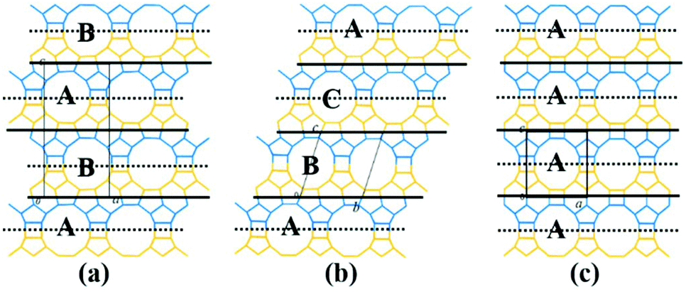 | ||
| Fig. 4 Three periodic connection modes of the interphase layer on the 2D plane (the ac plane or the bc plane). | ||
(2) As shown in Fig. 4b, the interphase layers follow the consecutive sequence +1/3, +1/3, +1/3… (or −1/3, −1/3., −1/3…), and the 12-membered ring channels present the ABCABC… type stacking sequences viewed on the ac (or bc) plane.
(3) As shown in Fig. 4c, the interphase layers are arranged without any translation, and the 12-membered ring channels present the AAA… type stacking sequences viewed on the ac (or bc) plane.
Zeolite beta has a typical 3D structure, and the stacking faults could arise from the random translations of the layers of the framework by ±1/3 of the lattice repeated in the a and b axis direction. Therefore, the periodic stacking sequences of interphase layers on both the ac plane and bc plane should be considered simultaneously. The three periodic connection modes of interphase layers on the 2D plane can be combined in the 3D space, thus providing C23 = 6 possible structural modes corresponding to the six hypothetical polymorphs of zeolite beta:
(1) When the interphase layers stacked as shown in Fig. 4a on both the ac plane and bc plane, the structure obtained is polymorph-A of zeolite beta.
(2) When the interphase layers stacked as shown in Fig. 4b on both the ac plane and bc plane, the structure obtained is polymorph-B of zeolite beta.
(3) When the interphase layers stacked as shown in Fig. 4c on both the ac plane and bc plane, the structure obtained is polymorph-C of zeolite beta.
(4) When the interphase layers stacked as shown in Fig. 4a on the ac plane and stacked as shown in Fig. 4b on the bc plane, the structure obtained is polymorph-CH of zeolite beta, an ordered intergrowth structure by polymorph-A and polymorph-B.
(5) When the interphase layers stacked as shown in Fig. 4b on the ac plane and stacked as shown in Fig. 4c on the bc plane, the structure obtained is polymorph-D of zeolite beta, an ordered intergrowth structure by polymorph-B and polymorph-C.
(6) When the interphase layers stacked as shown in Fig. 4a on the ac plane and stacked as shown in Fig. 4c on the bc plane, the structure obtained is polymorph-E of zeolite beta, an ordered intergrowth structure of polymorph-A and polymorph-C.
Detailed information on the six hypothetical polymorphs of zeolite beta is listed in Table 2, including the translation modes between adjacent layers, space groups, cell parameters, and channel characteristics. According to the structural data, the theoretical XRD patterns of the six hypothetical polymorphs can be simulated. As shown in Fig. 5, these different polymorphs have close but different characteristic diffraction peak positions, primarily at the low-angle region, which is widely accepted as the fingerprint area of zeolite beta (2θ = 5–10°).
 | ||
| Fig. 5 Simulated XRD patterns of six hypothetical polymorphs of zeolite beta. | ||
| No. | Periodic translation modes between adjacent layers along the a and b axis direction (a, b) | Space group | Cell parameters | Channel characteristics | Polymorph | Synthetic method |
|---|---|---|---|---|---|---|
| 1 | (1/3, 0), (0, 1/3), (−1/3, 0), (0, −1/3), (1/3, 0), (0, 1/3), (−1/3, 0), (0, −1/3)… | P4122 | a = b = 12.6 Å, c = 26.2 Å | Helix | A | Ref. 39–51 |
| 2 | (1/3, 0), (0, −1/3), (−1/3, 0), (0, 1/3), (1/3, 0), (0, −1/3), (−1/3, 0), (0, 1/3)… | P4322 | a = b = 12.6 Å, c = 26.2 Å | Helix | A | |
| 3 | (1/3, 0), (0, 1/3), (1/3, 0), (0, 1/3) … | C2/c | a = b = 17.9 Å, c = 14.3 Å, β = 114.8° | Inclined | B | Ref. 24, 25 and 52–54 |
| 4 | (1/3, 0), (0, 1/3), (−1/3, 0), (0, 1/3), (1/3, 0), (0, 1/3), (−1/3, 0), (0, 1/3)… | P2/c | a = b = 12.5 Å, c = 27.6 Å, β = 107.5° | Inclined | CH | Ref. 55 |
| 5 | (0, 0), (0, 0), (0, 0), (0, 0)… | P42/mmc | a = b = 12.8 Å, c = 13.0 Å | Straight | C | Ref. 25, 26 and 56–59 |
| 6 | (1/3, 0), (0, 0), (1/3, 0), (0, 0)… | P2/m | a = 12.6 Å, b = 12.8 Å, c = 14.0 Å, β = 107.6° | Straight | D | Ref. 60 |
| 7 | (1/3, 0), (0, 0), (−1/3, 0), (0, 0), (1/3, 0), (0, 0), (−1/3, 0), (0, 0), … | P/cmm | a = 12.6 Å, b = 12.8 Å, c = 25.8 Å | Zigzag | E | Ref. 60 |
2.2 Actual structure of zeolite beta
The six building models described above, corresponding to the six hypothetical polymorphs of zeolite beta, only consider the connection and symmetry of crystallography, which is an ideal state. Polymorph-A and polymorph-B were first determined in 1998, and the four remaining polymorphs with regular structure are hypothetical at that time. According to the hypothetical models, these polymorphic structures can be analysed by computer simulation. Tomlinson et al. performed an energy minimisation calculation using a purely siliceous structure for polymorph-A, polymorph-B, and polymorph-C and confirmed the stability of the polymorphic (A, B, and C) structures for zeolite beta proposed by Newsam et al.61 The results of calculations show that the lattice energy of polymorph-A per SiO2 unit was essentially equal to that of polymorph-B. This partly explains why an almost random stacking sequence of polymorph-A and polymorph-B is found in zeolite beta, while the particular double 4-membered ring (D4R) units in polymorph-C lead to an excessive structural tension so that the lattice energy of polymorph-C was obviously higher than that of the former two.62 Polymorph-C would therefore be marginally less stable, but given appropriate conditions, it may be possible to synthesize this pure structure.Polymorph-CH, -D, and -E can be regarded as an ordered intergrowth by two of these three polymorphs (A, B, and C), thus exhibiting more ideal structure. Since the lattice energy of polymorph-C is higher than that of polymorph-A and polymorph-B, it would be difficult for polymorph-C to stack with the other two polymorphs effectively, thus polymorph-D and polymorph-E are less likely to exist in practice. In practice, we usually just consider the intergrowth of polymorph-A, -B, and -C in zeolite beta, while in most of the synthetic zeolite betas, there are only two polymorphs, polymorph-A and polymorph-B, especially in the aluminosilicate zeolite beta and pure silica zeolite beta, which are synthesized in the absence of germanium.
Polymorph-A and polymorph-B have identical building units and highly similar thermodynamic stability, which makes them almost completely disordered during the growth of zeolite beta. The overall structure of normal zeolite beta is an intergrowth of polymorph-A and polymorph-B in nearly equal proportions, and there may be a very small but negligible amount of polymorph-C existing in practice. Fig. 6 gives an example of the intergrowth structure in zeolite beta. The grey fold lines are added to mark the stacking sequences of the 12-membered ring channels. The stacking segments of three different polymorphs, polymorph-A, -B, and -C, can be clearly observed in the intergrowth structure of zeolite beta. In the actual structure of zeolite beta, the stacking faults would be more complex and more disordered.
 | ||
| Fig. 6 (010)-Projection of intergrowth structure of zeolite beta. | ||
The highly disordered framework of zeolite beta causes a slower research progression in the determination of polymorphic composition. To date, there is still no advanced characterization technology that can accurately determine the proportion of polymorphs in zeolite beta. At present, the most widely used method to determine the proportion of polymorphs in zeolite beta is a DIFFaX program on the basis of a general recursion algorithm developed by Treacy et al. in 1991.63 By performing the DIFFaX program, we can calculate the kinematical diffraction intensities from the crystals containing coherent planar faults and simulate powder XRD patterns for several synthetic zeolite systems that contain high densities of stacking faults, for example, zeolite beta.
As we know, zeolite beta provides a near extreme example of crystallographic faulting. The high densities of stacking faults lead to the complex powder XRD patterns, which usually comprise both sharp and broad diffraction peaks. However, by performing DIFFaX program, the XRD patterns of zeolite beta with different polymorph ratios of A/B could be simulated, as shown in Fig. 7. A more detailed division of simulated XRD patterns in the fingerprint area is shown in Fig. 8. By comparing the shapes and degrees (2θ) of the low-angle peaks in the experimental patterns with the simulated series (Fig. 8), the polymorphic compositions could be approximately determined. Based on this method, Treacy et al. determined that the ratio of polymorph-A and polymorph-B in the normal zeolite beta is 44![[thin space (1/6-em)]](https://www.rsc.org/images/entities/char_2009.gif) :56,63–65 which is in good agreement with that obtained from the electron micrographs, suggesting a slight preference for polymorph B.
:56,63–65 which is in good agreement with that obtained from the electron micrographs, suggesting a slight preference for polymorph B.
 | ||
| Fig. 7 Simulated XRD patterns of zeolite beta with different polymorph ratios of A/B. | ||
 | ||
| Fig. 8 Simulated XRD patterns of zeolite beta with different portions of polymorph A (74 A represents the composition of zeolite beta is 74% polymorph A and 26% polymorph B). | ||
2.3 Chiral feature of polymorph-A in zeolite beta
Zeolite beta possesses a four-connected framework structure disordered along the c axis direction, giving rise to extensive interplanar stacking faults. The stacking faults do not significantly affect the accessible pore volume, but influence the tortuosity of the pore connectivity.57 All the three polymorphs (A, B, and C) have similar 3D 12-membered ring pore sizes, straight 12-membered ring channels parallel to the a and b axis directions, but different channel features along the c axis direction. Polymorph-B crystallizes in the space group C2/c (Table 2), exhibiting achiral inclined channel (Fig. 9b). Polymorph-C crystallizes in the space group P42/mmc (Table 2), exhibiting achiral straight channel along the c axis direction (Fig. 9c). However, polymorph-A crystallizes in the space group P4122 or P4322 (Table 2), corresponding to the formation of two enantiomorphs. For polymorph-A, the building layers may stack in a purely right-handed (RRRR…) or left-handed (LLLL…) manner (Fig. 10), exhibiting a pair of chiral helical channels along the c axis direction with a mirror symmetry (Fig. 9a). Pure polymorph-A with chiral pore structure might have potential values for asymmetric catalysis and chiral separations. Its specific structure also suggests the possibility of synthesis assisted by an appropriate chiral organic template. | ||
| Fig. 9 Channel characteristics of polymorph-A (a), polymorph-B (b), and polymorph-C (c). | ||
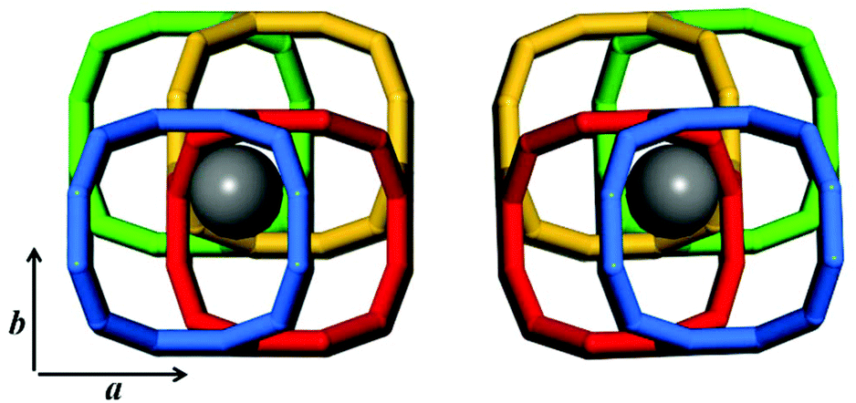 | ||
| Fig. 10 A pair of helix channels of polymorph-A viewed along the c axis. | ||
3. Synthesis of chiral zeolite beta
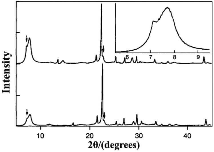
The synthesis of pure polymorph-A is an extremely attractive target because the chiral feature of its channel system suggests that this structure could be used in catalytic reactions or separation processes involving chiral compounds. Over the past few decades, many efforts have been made to synthesize zeolite beta in its pure polymorph-A form, but with little success.Since the chiral structure of polymorph-A in zeolite beta has been reported,13–15 Davis et al. started to create the chiral zeolite beta by introducing chiral organic molecules into the synthesis procedure, with the hopes of “templating” and targeting an enantiomer of polymorph A.39,66,67 They did successfully synthesize an interesting zeolite beta sample that contains slightly larger domains of polymorph-A by using an undisclosed chiral template molecule. Fig. 11 illustrates the powder XRD patterns of the normal zeolite beta and the zeolite beta synthesized by Davis and the simulated XRD pattern of the pure polymorph-A. The diffraction peak at the lower angle region indicates that the sample synthesized using the undisclosed chiral template molecule has, on average, larger domains of polymorph A than that of the normal zeolite beta. Note that XRD patterns cannot reveal whether the domains of polymorph-A is racemic or enhanced in one enantiomorph. Despite this, the preliminary experimental result shows that the synthesis of pure polymorph-A by using special chiral organic template molecule should be feasible.
 | ||
| Fig. 11 XRD patterns of the normal zeolite beta (a), the simulated pure polymorph A (b), and the zeolite beta synthesized using the chiral template molecule (c).39 Adapted with permission from ref. 39, © 1992 American Chemical Society. | ||
Davis et al. never discussed the organic template molecule they used because of the concern about its toxicity.9 They just enumerated that an appropriate organic template molecule should have the following attributes. First and foremost, the template molecule should be chiral. Second, the size of the template molecule should be sufficient to interact with the framework over distances that determine the chirality of the framework, such as a length that can distinguish the direction of a helical turn in the pore. Third, the template molecule should be stable under the synthesis conditions of high temperatures and pH. Fourth, the template molecule should be rigid to minimize obtainable confirmations during the synthesis. Fifth, the template molecule should be unable to rotate with the pore structure otherwise the chirality would be lost. Very recently, Davis et al. synthesized two enantiomerically enriched polycrystalline zeolites (STW type) following the designed rules for chiral template molecules,68 which might also be useful for guiding the later investigations for chiral zeolite beta.
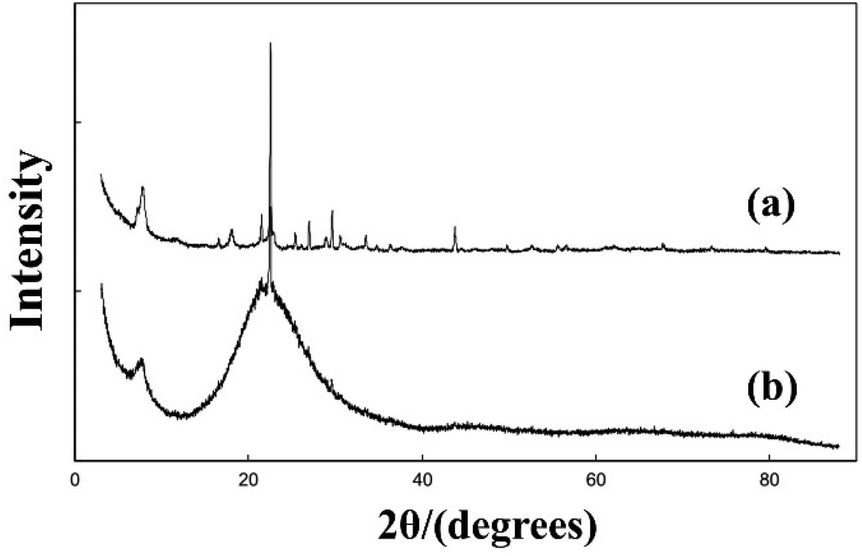
In 1996, Camblor et al. presented the unseeded synthesis of pure silica zeolite beta from a hydrothermal system containing achiral tetraethylammonium cations (TEA+) as organic structure directing agents (OSDAs) and fluoride ions as mineralizing agents at near neutral pH.40 The final composition of the mixture is SiO2:0.54 TEAOH:0.54 HF:7.25 H2O. After crystallization for 39 hours, the obtained pure silica zeolite beta shows an enhanced crystallinity, hydrophobicity, and thermal stability due to the almost complete absence of connectivity defects. The XRD pattern of the pure silica zeolite beta (Fig. 12) is clearly distinguished with the normal zeolite beta. Compared with the simulated XRD patterns calculated by the DIFFaX program, the shoulder at the low-angle region of the first diffraction peak suggests that this material contains slightly more polymorph-A than polymorph-B. However, Camblor et al. did not provide a further definitive analysis of this material.
 | ||
| Fig. 12 XRD patterns of pure silica zeolite beta as made (bottom) and calcined at 580 °C (top and inset).40 Adapted with permission from ref. 40, © 1996 The Royal Society of Chemistry. | ||
In 2003, Xia et al. synthesized a series of metal-incorporated (including Pt, Pd, W, etc.) zeolite beta in the fluoride medium.41 They added the compounds containing Pt, Pd, or W into the mixture of TEOS and TEAOH solution (SiO2:0.54 TEAOH), and then kept them stirring overnight at ambient temperature to form a homogeneous sol. Thereafter, the H-beta seeding powder and HF (SiO2:0.57 HF) were added into the homogeneous sol in sequence. After hydrothermal crystallization, the solids were washed, dried, calcined, and pre-reduced if needed. The synthetic process is based on that reported by Camblor et al., and the majority of these metal-incorporated materials showed similar XRD patterns (Fig. 13) with the pure silica zeolite beta prepared by Camblor et al. Note that the diffraction peak at about 8.8° in the XRD patterns of some samples indicates that there may be some crystalline impurities such as ZSM-5 or ZSM-12 (<5%).
 | ||
| Fig. 13 XRD patterns of metal-incorporated zeolite beta synthesized in a fluoride medium.41 Adapted with permission from ref. 41, © 2003 Elsevier. | ||
In 2008, Takagi et al. developed a new crystallization method to synthesize zeolite beta in an acidic medium in the presence of a chiral rhodium complex or chiral amine.42 For the rapid crystallization method, they first mixed the gel with the composition SiO2:0.54 TEA+:0.54 F−:7.5 H2O and carried out a nucleation process at 413 K for 50 hours. After quenching, they added chiral rhodium complex of [Rh(bpy)3](HF2)3 into the nucleated gel and adjusted the pH to 4 with HF. Then, the final composition of the gel was SiO2:0.54 TEA+:4.0 F−:4.5 H2O:0.30 Rh. The crystallization needs to be performed at 373 K for 2 months. For another recrystallization method, the steps are more complicated and the synthesis cycle is also over one month.
The XRD patterns of the zeolite beta synthesized by the rapid crystallization method and recrystallization method in acidic medium are shown in Fig. 14. Then, Takagi et al. evaluated the proportion of polymorphs by a peak separation method using XRD profiles. However, the experimental XRD patterns that they have reported (as shown in Fig. 14) are very similar to those of the normal zeolite beta, indicating that the proportion of polymorph-A in zeolite beta was not significantly increased as they reported.
 | ||
| Fig. 14 XRD patterns of the nucleated gel (a) and the product (b) synthesized by the rapid crystallization method in an acidic media.42 Adapted with permission from ref. 42, © 2008 Elsevier. | ||
Subsequently, Taborda et al. synthesized pure silica zeolite beta, Al–Si-beta, and Ti–Si-beta by an aging–drying method.43,44 These samples are synthesized by slight modifications of the procedures reported by Camblor et al. Taking the synthesis of pure silica zeolite beta as an example, the obtained homogeneous gels with the composition SiO2:0.54 TEAOH:0.7 HF were aged in a fume cupboard and dried at ambient temperature for several days. The organic solvent such as diisopropylamine (DIPA), diisobutylamine (DIBA,) or R-(−)-2-butanol (RButOH) was added at the end of the aging–drying process. Finally, the dried gels were transferred into autoclaves and heated at 413 K for 12 days. The powder XRD patterns of these as-synthesized samples are shown in Fig. 15. A closer view of the XRD patterns of Si–RButOH reveals that the first peak has a small shoulder or spur to the left, indicating that the addition of RButOH did slightly increase the proportion of polymorph-A. However, the enrichment of polymorph-A in these samples did not reach the values proposed by Taborda et al. calculated with a peak separation method.
 | ||
| Fig. 15 XRD patterns of the selected as-synthesized samples.43 Adapted with permission from ref. 43, © 2011 Elsevier. | ||
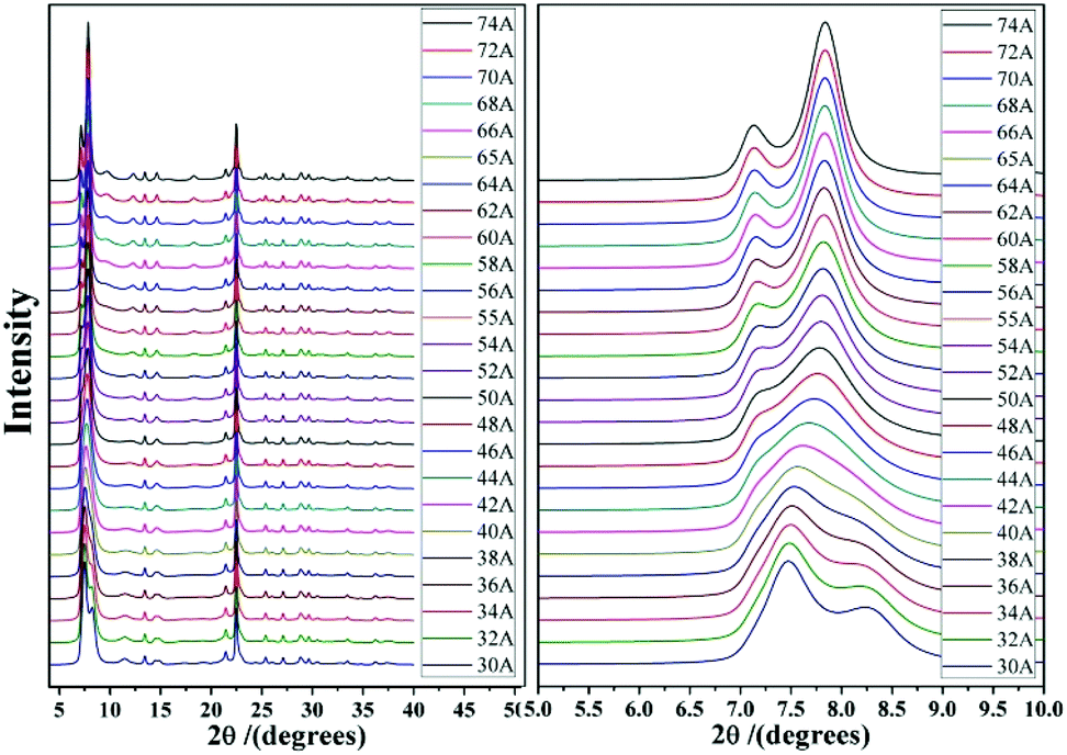
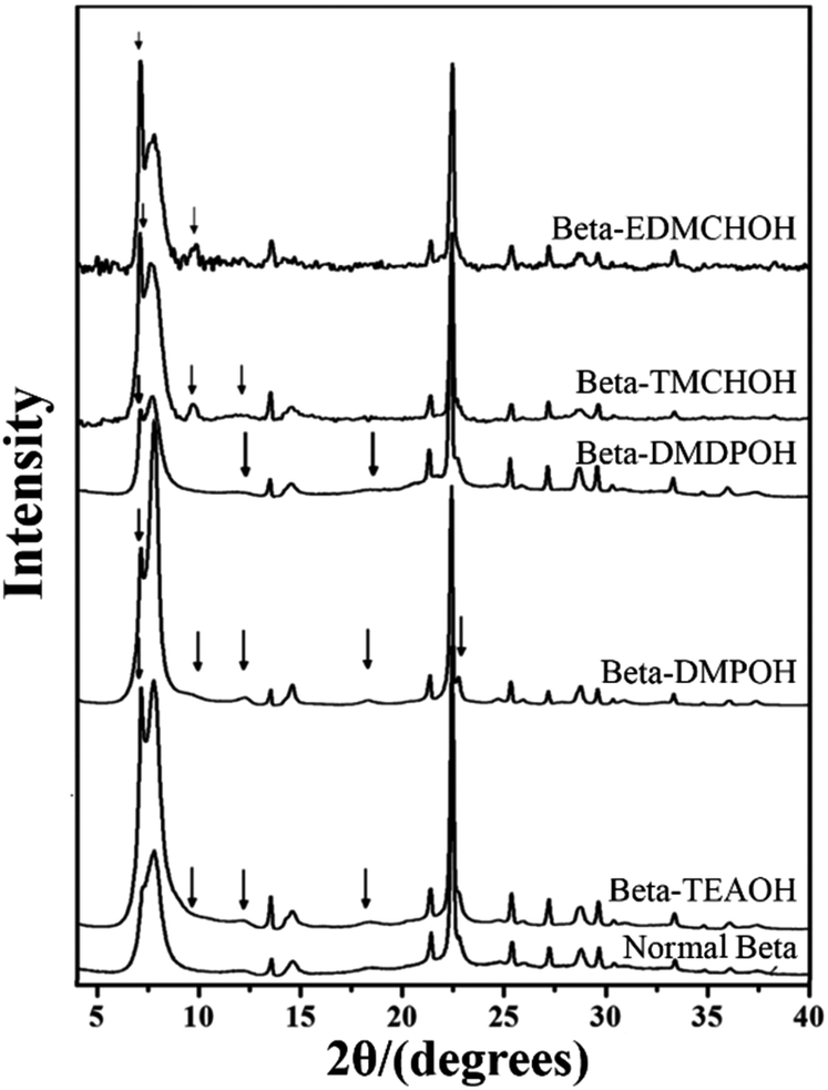
Until recently, from 2013 to 2015, Tong et al. and Guo et al. successively synthesized the chiral polymorph-A enriched pure silica zeolite beta with an extremely concentrated fluoride route using achiral OSDAs.45–47 In addition to the commercially available OSDA of TEAOH, they also synthesized other four achiral OSDAs (as shown in Fig. 16), i.e., dimethyldiisopropylammonium hydroxide (DMDPOH), N,N-dimethyl-2,6-cis-dimethylpiperdinium hydroxide (DMPOH), N-ethyl-N,N-dimethylcyclohexanaminium hydroxide (EDMCHOH), and N,N,N-trimethylcyclohexanaminium hydroxide (TMCHOH). Typically, they added TEOS to the OSDA solution with the molar ratio SiO2:0.5 OSDA. After the hydrolysis of TEOS, they kept the mixture stirring under an infrared lamp to evaporate the generated ethanol and most of the water. Then, they put the thick gel into an 80 °C oven for further dehydration, which often needs 3–6 days until the H2O/SiO2 ratio reached approximately 0.3. The solid gel was ground to a powder and HF was added under continuous manual stirring with the molar ratio SiO2:0.5 HF. Finally, the uniform mixture was transferred into autoclaves and heated at 423 K for 4–7 days. The powder XRD patterns of the calcined samples are shown in Fig. 17, and the arrows are added to show the characteristic diffraction peaks related to the chiral polymorph-A of zeolite beta. By comparing the shapes and degrees of the broadened low-angle peaks, the proportion of polymorph A in the beta-TEAOH, beta-DMPOH, beta-DMDPOH, beta-EDMCHOH, and beta-TMCHOH was determined to be approximately 65%, 65%, 60%, 70%, and 70%, respectively. HRTEM images of beta-TEAOH shown in Fig. 18 also clearly show the dominance of polymorph A. Tong et al. proposed that the amount of water in the final mixture (H2O/Si) was the key to the enrichment of polymorph-A.
 | ||
| Fig. 16 The achiral OSDAs used to synthesize chiral zeolite beta by Tong et al., Guo et al., and Zhang et al.46,47,49 | ||
 | ||
| Fig. 17 XRD patterns of the calcined zeolite betas, the arrows show the characteristic peaks related to the chiral polymorph A of zeolite beta.47 Adapted with permission from ref. 47, © 2018 Springer Nature. | ||
 | ||
| Fig. 18 HRTEM images of beta-TEAOH crystals.47 Adapted with permission from ref. 47, © 2018 Springer Nature. | ||
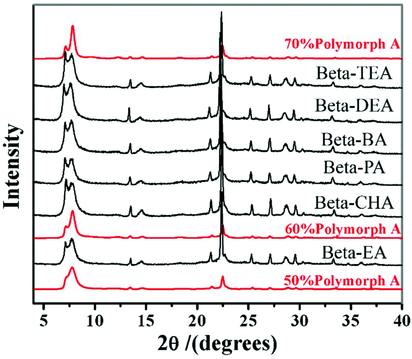
However, in 2016, with the same extremely concentrated fluoride route, Lu et al. found that the introduction of Al3+ species into the identical starting mixture leads to an acceleration of crystallization, but a decrease in the proportion of polymorph-A in zeolite beta.69 They started to identify the factors promoting the enrichment of chiral polymorph-A in zeolite beta. Previously, Tong et al. has found that the dehydration process of initial gel in an 80 °C oven would lead to a partial decomposition of TEAOH via Hofmann degradation to form triethylamine (TEA).47 The single pulse 13C MAS NMR data shows that the molar ratio of TEAOH to TEA in the dehydrated mixture was approximately 0.61, implying that the decomposition product (TEA) might play an important role on the enrichment of polymorph-A. Then, Lu et al. optimized the degradation process by freeze-drying, which can effectively avoid the decomposition of TEAOH and control the composition of gels accurately.48 With the freeze-drying process, they synthesized approximately 65% polymorph-A enriched zeolite beta by a co-template strategy (Fig. 19), using triethylamine (TEA), diethylamine (DEA), ethylamine (EA), n-propylamine (PA), n-butylamine (BA), or cyclohexylamine (CHA) as the second structure-directing agent (SDA2:co-template) together with the reduced amount of TEAOH. Thus, the molar composition of the final mixture is SiO2:0.25 TEAOH:0.25 SDA2:0.5 HF. With this co-template strategy, the consumption of expensive TEAOH can be significantly reduced.
 | ||
| Fig. 19 XRD patterns of the zeolite betas synthesized by a co-template strategy.48 Adapted with permission from ref. 48, © 2016 Elsevier. | ||
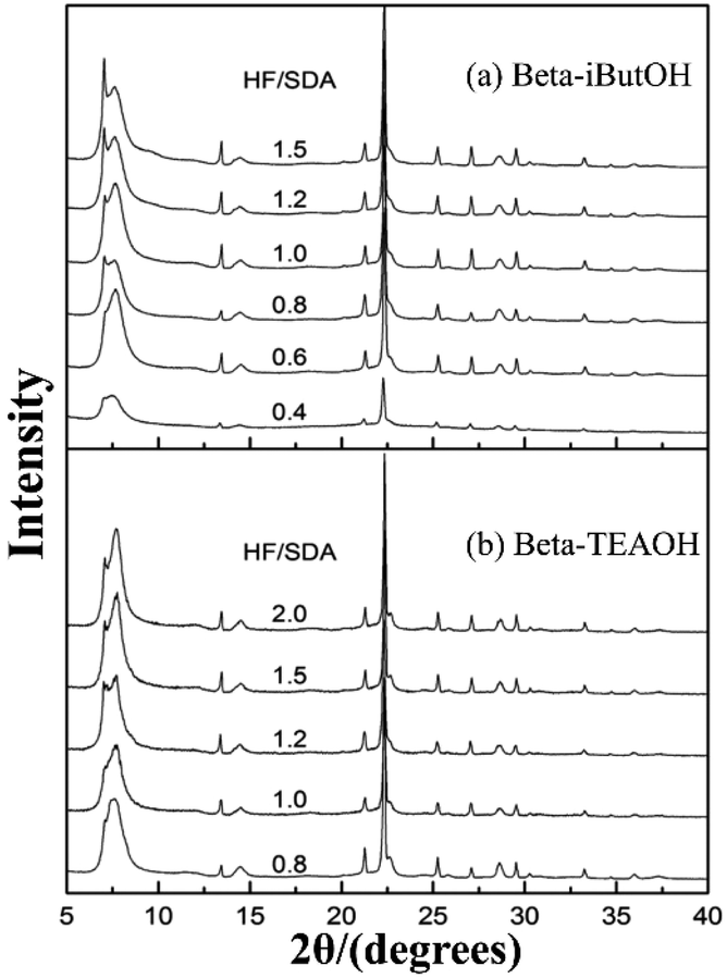
In 2016, Zhang et al. synthesized a chiral polymorph-A enriched zeolite beta in a HF-concentrated system with a variety of achiral OSDAs.49 Unlike the extremely concentrated routes reported by Tong et al., they controlled the high HF concentration (HF/OSDA > 1.0) in the synthesis medium, instead of the H2O/SiO2 ratio. Besides TEAOH, they also synthesized three achiral pyrrole-based OSDAs (as shown in Fig. 16), i.e., N-isopropyl-N-methylpyrrolidinium hydroxide (iProOH), N-isobutyl-N-methyl-pyrrolidinium hydroxide (iButOH), and N-isopentyl-N-methylpyrrolidinium hydroxide (iPenOH). Their synthetic procedure is based on the previous fluoride synthesis route reported by Camblor et al. with slight modifications. When the molar composition of the final mixture is SiO2:0.5 OSDA:5 H2O:n HF (n > 1.0), the zeolite beta with polymorph-A enriched feature (55–65% A) was obtained (Fig. 20). They also found that when a large amount of HF exist in the synthesis system, a vast majority of F− converts to SiF62− and a buffered system of H+ and F− is formed in the synthesis system. They speculated that the buffer could restrict the release of F− to a small but continuous supply for the crystallization process, which might promote the enrichment of polymorph-A in zeolite beta.
 | ||
| Fig. 20 XRD patterns of zeolite beta sample synthesized with increasing HF/SDA ratios.49 Adapted with permission from ref. 49, © 2016 The Royal Society of Chemistry. | ||
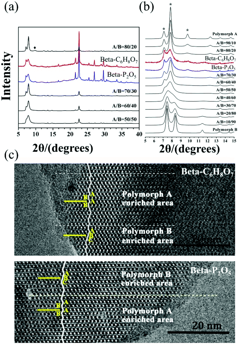
It is not difficult to find that HF has been widely used in the previously reported synthesis methods. However, HF is known to be highly corrosive and toxic, which is not encouraged and should be handled with great caution if used. Very recently, Lu et al. also found that excess HF did enrich the polymorph-A during the crystallization.50 However, they excluded the essential influence of F− by controlling the variables. They made a thorough investigation on the essential key factor promoting the enrichment of chiral polymorph-A in zeolite beta and experimentally confirmed that the acidity of the initial mixture greatly affected the proportion of chiral polymorph-A in the product zeolite beta. Based on this discovery, they developed an acid-assisted route to synthesize polymorph-A enriched zeolite beta. Similarly, they added TEOS to the TEAOH solution with the molar ratio SiO2:0.25 TEAOH. After the hydrolysis of TEOS, they kept the mixture stirring overnight and then put it in a freeze drier for 2 days until the H2O/SiO2 ratio reached approximate 1. Subsequently, the solid NH4F with 0.5 times SiO2 in mole was added into the dry gel and mixed homogeneously by grinding. Finally, an appropriate amount of acid additive, i.e., oxalic acid (H2C2O4), citric acid (C6H8O7), phosphorus pentoxide (P2O5), acetic acid (CH3COOH), or phosphoric acid (H3PO4) was added and the resulting uniform mixture was transferred into autoclaves. The crystallization of polymorph-A enriched zeolite beta takes 10 days under acidic conditions at 423 K. Fig. 21 shows the powder XRD patterns and HRTEM images of the beta-C6H8O7 and beta-P2O5. Notably, the appearance of the characteristic peak at 2θ = 9.7° marked with the asterisks in Fig. 21(a and b) indicates that the proportion of chiral polymorph-A in beta-C6H8O7 and beta-P2O5 were remarkably improved to greater than 70%. The alternation areas observed in Fig. 21c reveals that the intergrowths inside these bulk crystals and the polymorph-A was dominant in beta-C6H8O7 and beta-P2O5.
 | ||
| Fig. 21 XRD patterns (a) in the fingerprint area (b) with different polymorph ratios of A/B, and HRTEM images (c) aligned along the [100] direction of beta-C6H8O7 and beta-P2O5.50 Adapted with permission from ref. 50, © 2018 The Royal Society of Chemistry. | ||
Considering such results, Lu et al. speculated that the slow nucleation rate caused by acidic medium might be an essential reason for the enrichment of chiral polymorph-A in zeolite beta. With this speculation, they selected several alcohols instead of acid additives to suppress the nucleation70 and successfully synthesized chiral polymorph-A enriched zeolite beta.51 Their preparation process is very similar to the acid-assisted synthesis method except for the use of ethanol (C2H5OH), methanol (CH3OH), or polyethylene glycol (PEG-400, 2000, 4000, 10000) instead of acid as additives. The XRD patterns (shown in Fig. 22) of the calcined zeolite beta prepared with different alcohol additives indicate that the proportion of the chiral polymorph-A is approximately 65%–70% under the optimal conditions. The HRTEM images of beta-PEG-10000 (Fig. 23) show that the distribution of polymorph-A in the crystals is not uniform but is dominating.
 | ||
| Fig. 22 XRD patterns of the calcined zeolite beta prepared with different alcohol additives.51 Adapted with permission from ref. 51, © 2018 The Royal Society of Chemistry. | ||
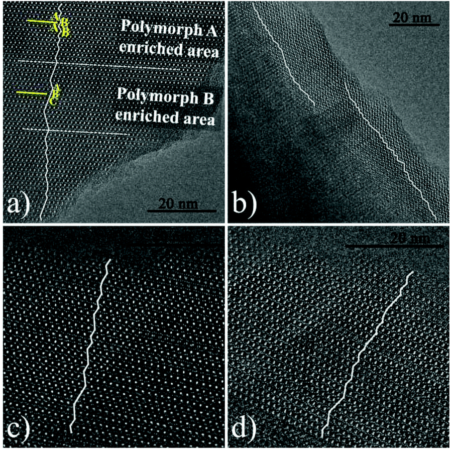 | ||
| Fig. 23 HRTEM images of beta-PEG-10000 aligned along the [100] direction. The fold line is added to mark the stacking sequences of the 12-membered ring channels. The proportion of polymorph A in (a), (b), (c), and (d) is 61.70%, 68, 18%, 73.08, and 75.00%, respectively.51 Adapted with permission from ref. 51, © 2018 The Royal Society of Chemistry. | ||
Over the past few decades, researchers have devoted many efforts to selectively crystallize chiral polymorph-A of zeolite beta (Table 3). Although the success is limited, the researchers still work on it.
| Molar composition | Specific condition | Crystallization | Ref. |
|---|---|---|---|
| Undisclosed | Undisclosed chiral OSDA | Undisclosed | 39 |
| SiO2:0.54 TEAOH:0.54 HF:7.25 H2O |
Rotating oven | 413 K, 39 hours | 40 |
| SiO2:0.54 TEAOH:0.57 HF:10.6 H2O:n M |
Metal-incorporated | 413 K, 6–12 days | 41 |
| SiO2:0.54 TEAOH:0.54 HF:7.5 H2O:0.30 Rh |
Chiral rhodium complex | 373 K, 2 months | 42 |
| SiO2:0.54 TEAOH:0.7 HF:10.16 H2O:1.15 DIBA |
Aging–drying method | 413 K, 12 days | 43 |
| SiO2:0.54 TEAOH:0.7 HF:10.15 H2O:1.15 DIPA |
|||
| SiO2:0.54 TEAOH:0.7 HF:10.09 H2O:1.0 R-butanol |
|||
| SiO2:0.5 OSDA:0.5 HF:0.3 H2O (OSDA = TEAOH, DMPOH, DMDPOH, TMCHOH, or EDMCHOH) |
Extremely concentrated fluoride route; achiral OSDA | 423 K, 4–7 days | 45–47 |
| SiO2:0.25 TEAOH:0.25 SDA2:0.5 HF:0.7 H2O (SDA2 = TEA, DEA, EA, PA, BA, or CHA) |
Co-template method | 423 K, 7 days | 48 |
| SiO2:0.5 OSDA:5 H2O:n HF (n > 1.0) (OSDA = TEAOH, iProOH, iButOH, or iPenOH) |
HF-concentrated system; achiral OSDA | 448 K, 7 days | 49 |
| SiO2:0.25 TEAOH:0.25 NH4F:n acid (n acid = 0.12 C6H8O7, 0.12 P2O5, 0.1 CH3COOH, 0.15 H2C2O4, or 0.06 H3PO4) |
Acid-assisted method | 423 K, 10 days | 50 |
| SiO2:0.25 TEAOH:0.25 NH4F:0.5 H2O:n alcohol (n alcohol = 0.6 EtOH, 0.65 MeOH, 0.045 PEG-400, 0.04 PEG-2000, 0.05 PEG-4000, or 0.03 PEG-10000) |
Alcohol additives | 423 K, 7 days | 51 |
4. Application of chiral zeolite beta
In recent years, the increasing demands for enantiomerically pure compounds in products such as pharmaceuticals, fragrances, and agrochemicals have fostered the development of preparation methods affording pure enantiomers. Asymmetric catalysis, enantioselective adsorption and separation are of great current importance. Unfortunately, the number of chiral solids that can perform enantioselective application are very limited.71 Chiral polymorph-A of zeolite beta contains a 3D 12-membered ring pore systems in which the pore along the c-direction of the crystal is helical following a 4-fold screw axis (right-handed with the space group symmetry P4122 or left-handed with the space group symmetry P4322, respectively). The unique chiral structure of zeolite beta makes it a candidate material for applications in the preparation of enantiomerically pure compounds.72Davis et al. first successfully synthesized a chiral zeolite beta that has more polymorph-A than the normal zeolite.39 In order to evaluate whether this polymorph-A slightly enriched zeolite beta (∼50% A) can perform enantioselective catalysis, they placed it in its acidic form in contact with trans-stilbene oxide and water (as shown in Fig. 24). Then, they tested the optical activity of the recovered reaction products. The results showed that the reaction products have an enantiomeric excess (ee) of 5% ((R,R)-diol), while normal zeolite beta produced an ee value of zero under the same conditions. Additionally, they mixed this chiral polymorph-A slightly enriched zeolite beta or normal zeolite beta with a racemic mixture of the diols ((±)-hydrobenzoin) several times. The results showed that chiral polymorph-A slightly enriched zeolite beta could preferentially adsorb the R,R isomer (ee again <5%), while normal zeolite beta could not. Although the ee values of these experiments are quite low, they are nonzero and outside the limits of experimental error. These results suggest that the use of a chiral zeolite beta to perform asymmetric catalysis, enantiomeric separations, and enantiomeric syntheses is feasible.
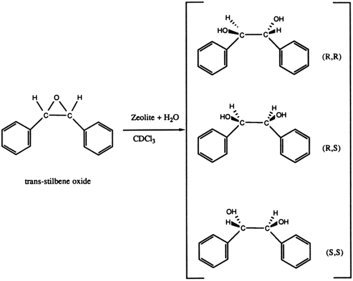 | ||
| Fig. 24 Reactions on chiral polymorph-A slightly enriched zeolite beta.39 Adapted with permission from ref. 39, © 1992 American Chemical Society. | ||
In 2003, Xia et al. performed the chiral hydrogenation of tiglic acid using Pt or Pd loaded chiral polymorph-A slightly enriched zeolite beta (∼50% A).41 The hydrogenised product α-methylbutyric acid has only one chiral center, which made it advantageous as a model molecule. When Pt or Pd loaded chiral polymorph-A enriched zeolite beta were applied in this reaction, about 9–11% ee value was obtained directly without any addition of chiral modifier, in which the R-(−)-enantiomer was dominant in the products, showing the influence of the chirality of pore channels of the catalyst. However, only a racemic product was acquired with an enantioselectivity close to zero when the Pd loaded normal zeolite beta was used in the identical reaction.
In 2004, Sacco carried out the adsorption of hydrobenzoin (1,2-diphenyl-1,2-ethanediol, a model enantiomeric species) on commercial normal zeolite beta. They mixed the normal zeolite beta and saturated racemic hydrobenzoin solution to study its ability to adsorb and potentially discriminate between its enantiomers. After the adsorption of a racemic mixture (50/50), a 48/52 solution was obtained, representing an approximately 4% enantiomeric excess. The results showed that zeolite beta can resolve racemic hydrobenzoin by selective adsorption, but the ee value was still low, which may be due to the low proportion of chiral polymorph A and its one single enantiomorph.
In 2015, Tong et al. performed the asymmetric epoxidation of β-methylstyrene and 1-phenyl-1-cyclohexene over polymorph-A enriched Ti-beta (∼65% A).47 For comparison, the normal Ti-beta with the same Ti/Si ratio was also applied to catalyse the identical asymmetric epoxidation. For the asymmetric epoxidation of β-methylstyrene, the Ti-beta with about 65% polymorph-A gave an ee value of 4.76% (Si/Ti = 60) or 5.67% (Si/Ti = 125), while the normal Ti-beta give negligible ee values of 0.12% (Si/Ti = 60) and 0.5% (Si/Ti = 125). For the asymmetric epoxidation of 1-phenyl-1-cyclohexene, the ee values for the cis-epoxides obtained on the chiral polymorph-A enriched Ti-beta (∼65% A, Si/Ti = 60) exceeds 10% (11.40%), which is much higher than that of the normal Ti-beta (1.41%). These studies indicate that chiral zeolite beta can perform enantioselective separations and syntheses, but no quantitative relation was observed between the ee value and the proportion of polymorph-A.
5. Conclusions and outlooks
Generally, this review has summarized the recent advances in the structure, synthesis, and application of chiral zeolite beta. The complex fault structure of zeolite beta has made its analysis difficult for a long time. Through decades of development and continuous efforts, there has been significant progress in the understanding of chiral zeolite beta. The potential chiral applications of chiral zeolite beta have attracted extensive attention from researchers. Some strategies toward the designed synthesis and selective crystallization of chiral polymorph-A in zeolite beta have been developed, such as using chiral OSDAs or additives, extremely concentrated fluoride route or high HF dosage system, co-template route, acid synthesis route, and alcohol-assisted route. However, some challenges still limit the application and development of chiral zeolite beta.(1) To further increase the proportion of polymorph-A in zeolite beta. Although great efforts have been made towards the synthesis of chiral polymorph-A, the proportion of polymorph-A in the resulting crystals is still limited. The crystallization mechanism of the polymorphs has not been clearly understood yet. How to break through the limitation of close lattice energies of polymorph-A and polymorph-B is still unclear, thus the synthesis of pure polymorph-A or polymorph-A highly enriched zeolite beta is one of the challenges.
(2) To induce the synthesis of single enantiotopic chiral polymorph-A. Chiral polymorph-A of zeolite beta contains a pair of asymmetric helix pores (enantiomorphic pair). The growing crystals of zeolite beta have “no memory” in the sense of the “handedness”. So far, the polymorph-A enriched zeolite beta synthesized are mostly racemic. Therefore, the practical chiral application of zeolite beta is limited by the actual composition. How to realize the symmetry breaking is still unclear, thus initiating the synthesis of chiral polymorph-A with single enantiomer is one of the challenges.
(3) To determine the proportion of polymorph-A and polymorph-B in the crystals of zeolite beta accurately. Zeolite beta has a high intergrowth structure that consists of several distinct but closely related polymorphs. Due to the complex structure of zeolite beta, the accurate determination of its polymorphic composition has always been one of the challenges. We expect that novel characterization methods can be developed to accurately provide information about the polymorphic composition of zeolite beta.
In summary, it is promising that chiral zeolite beta would play an important role in chiral applications. Selective crystallization of chiral polymorph-A, even the enantiomerically pure polymorph-A, has always been a very challenging and significant subject. Driven by this direction, more meaningful research studies are expected in the future.
Conflicts of interest
There are no conflicts to declare.Acknowledgements
We acknowledge financial support from the National Natural Science Foundation of China (21571075, 21621001, and 21835002), the 111 Project (B17020), and the Program for JLU Science and Technology Innovative Research Team.Notes and references
- J. Čejka, A. Corma and S. Zones, Zeolites and Catalysis: Synthesis, Reactions and Applications, Wiley-VCH Verlag GmbH & Co. KGaA, Weinheim, Germany, 2010 Search PubMed.
- S. Kulprathipanja, Zeolites in Industrial Separation and Catalysis, Wiley-VCH Verlag GmbH & Co. KGaA, Weinheim, Germany, 2010 Search PubMed.
- R. R. Xu, W. Q. Pang, J. H. Yu, Q. S. Huo and J. S. Chen, Chemistry of Zeolites and Related Porous Materials: Synthesis and Structure, WILEY-VCH Verlag GmbH & Co. KGaA, Weinheim, Germany, 2010 Search PubMed.
- C. Dryzun, Y. Mastai, A. Shvalb and D. Avnir, J. Mater. Chem., 2009, 19, 2062 RSC.
- E. Pidcock, Chem. Commun., 2005, 3457 RSC.
- H. D. Flack, Helv. Chim. Acta, 2003, 86, 905 CrossRef CAS.
- H. D. Flack and G. Bernardinelli, Cryst. Eng., 2003, 6, 213 CrossRef CAS.
- J. Yu and R. Xu, J. Mater. Chem., 2008, 18, 4021 RSC.
- M. E. Davis, ACS Catal., 2018, 8, 10082 CrossRef CAS.
- C. E. Song and S.-G. Lee, Chem. Rev., 2002, 102, 3495 CrossRef CAS PubMed.
- A. Baiker, Curr. Opin. Solid State Mater. Sci., 1998, 3, 86 CrossRef CAS.
- Ch. Baerlocher and L. B. McCusker, Database of Zeolite Structures: http://www.iza-structure.org/databases/.
- J. Higgins, R. B. LaPierre, J. Schlenker, A. Rohrman, J. Wood, G. Kerr and W. Rohrbaugh, Zeolites, 1988, 8, 446 CrossRef CAS.
- J. M. Newsam, M. M. J. Treacy, W. T. Koetsier and C. B. D. Gruyter, Proc. R. Soc. London, Ser. A, 1988, 420, 375 CrossRef CAS.
- M. M. J. Treacy and J. M. Newsam, Nature, 1988, 332, 249 CrossRef CAS.
- W. T. A. Harrison, T. E. Gier, G. D. Stucky, R. W. Broach and R. A. Bedard, Chem. Mater., 1996, 8, 145 CrossRef CAS.
- I. Boy, F. Stowasser, G. Schäfer and R. Kniep, Chem. – Eur. J., 2001, 7, 834 CrossRef CAS.
- J. Sun, C. Bonneau, A. Cantin, A. Corma, M. J. Diaz-Cabanas, M. Moliner, D. Zhang, M. Li and X. Zou, Nature, 2009, 458, 1154 CrossRef CAS PubMed.
- X. Song, Y. Li, L. Gan, Z. Wang, J. Yu and R. Xu, Angew. Chem., Int. Ed., 2009, 48, 314 CrossRef CAS PubMed.
- R. W. Broach and R. M. Kirchner, Microporous Mesoporous Mater., 2011, 143, 398 CrossRef CAS.
- A. K. Cheetham, H. Fjellvg, T. E. Gier, K. O. Kongshaug, K. P. Lillerud and G. D. Stucky, Stud. Surf. Sci. Catal., 2001, 135, 158 CrossRef.
- L. Tang, L. Shi, C. Bonneau, J. Sun, H. Yue, A. Ojuva, B.-L. Lee, M. Kritikos, R. G. Bell, Z. Bacsik, J. Mink and X. Zou, Nat. Mater., 2008, 7, 381 CrossRef CAS PubMed.
- R. L. Wadlinger, G. T. Kerr and E. J. Rosinski, US Pat., 3793385, 1967 Search PubMed.
- A. Corma, M. Moliner, A. Cantin, M. J. Diaz-Cabanas, J. L. Lorda, D. L. Zhang, J. L. Sun, K. Jansson, S. Hovmoller and X. D. Zou, Chem. Mater., 2008, 20, 3218 CrossRef CAS.
- A. Cantin, A. Corma, M. J. Diaz-Cabanas, J. L. Jorda, M. Moliner and F. Rey, Angew. Chem., Int. Ed., 2006, 45, 8013 CrossRef CAS PubMed.
- A. Corma, M. T. Navarro, F. Rey, J. Rius and S. Valencia, Angew. Chem., Int. Ed., 2001, 40, 2277 CrossRef CAS PubMed.
- K. Tarach, K. Góra-Marek, J. Tekla, K. Brylewska, J. Datka, K. Mlekodaj, W. Makowski, M. C. Igualada López, J. Martínez Triguero and F. Rey, J. Catal., 2014, 312, 46 CrossRef CAS.
- L. Bonetto, M. A. Camblor, A. Corma and J. Pérez-Pariente, Appl. Catal., A, 1992, 82, 37 CrossRef CAS.
- S. Chen, Y. Yang, K. Zhang and J. Wang, Catal. Today, 2006, 116, 2 CrossRef CAS.
- K. S. N. Reddy, B. S. Rao and V. P. Shiralkar, Appl. Catal., A, 1993, 95, 53 CrossRef CAS.
- G. Bellussi, G. Pazzuconi, C. Perego, G. Girotti and G. Terzoni, J. Catal., 1995, 157, 227 CrossRef CAS.
- U. Freese, F. Heinrich and F. Roessner, Catal. Today, 1999, 49, 237 CrossRef CAS.
- P. Botella, A. Corma, J. M. López-Nieto, S. Valencia and R. Jacquot, J. Catal., 2000, 195, 161 CrossRef CAS.
- M. Moliner, Y. Román-Leshkov and M. E. Davis, Proc. Natl. Acad. Sci. U. S. A., 2010, 107, 6164 CrossRef CAS PubMed.
- J.-K. Lee and H.-K. Rhee, J. Catal., 1998, 177, 208 CrossRef CAS.
- J. Dijkmans, M. Dusselier, D. Gabriëls, K. Houthoofd, P. C. M. M. Magusin, S. Huang, Y. Pontikes, M. Trekels, A. Vantomme, L. Giebeler, S. Oswald and B. F. Sels, ACS Catal., 2015, 5, 928 CrossRef CAS.
- M. Tong, D. Zhang, L. Zhu, J. Xu, F. Deng, R. Xu and W. Yan, CrystEngComm, 2016, 18, 1782 RSC.
- P. A. Wright, W. Zhou, J. Pérez-Pariente and M. Arranz, J. Am. Chem. Soc., 2005, 127, 494 CrossRef CAS PubMed.
- M. E. Davis and R. F. Lobo, Chem. Mater., 1992, 4, 756 CrossRef CAS.
- M. A. Camblor, A. Corma and S. Valencia, Chem. Commun., 1996, 2365 RSC.
- Q. H. Xia, S. C. Shen, J. Song, S. Kawi and K. Hidajat, J. Catal., 2003, 219, 74 CrossRef CAS.
- Y. Takagi, T. Komatsu and Y. Kitabata, Microporous Mesoporous Mater., 2008, 109, 567 CrossRef CAS.
- F. Taborda, T. Willhammar, Z. Wang, C. Montes and X. Zou, Microporous Mesoporous Mater., 2011, 143, 196 CrossRef CAS.
- F. Taborda, Z. Wang, T. Willhammar, C. Montes and X. Zou, Microporous Mesoporous Mater., 2012, 150, 38 CrossRef CAS.
- M. Tong, W. Yan, J. H. Yu and R. R. Xu, Chem. J. Chin. Univ., 2013, 34, 494 CAS.
- W. Guo, W. Yan, R. R. Xu, Y. Wang and X. H. Mu, Chem. J. Chin. Univ., 2014, 35, 1363 CAS.
- M. Tong, D. Zhang, W. Fan, J. Xu, L. Zhu, W. Guo, W. Yan, J. Yu, S. Qiu, J. Wang, F. Deng and R. Xu, Sci. Rep., 2015, 5, 11521 CrossRef PubMed.
- T. Lu, R. Xu and W. Yan, Microporous Mesoporous Mater., 2016, 226, 19 CrossRef CAS.
- G. Zhang, B. Wang, W. Zhang, M. Li and Z. Tian, Dalton Trans., 2016, 45, 6634 RSC.
- T. Lu, L. Zhu, X. Wang, W. Yan, W. Shi and R. Xu, Inorg. Chem. Front., 2018, 5, 1640 RSC.
- T. Lu, L. Zhu, X. Wang, W. Yan, W. Shi and R. Xu, Inorg. Chem. Front., 2018, 5, 802 RSC.
- Y. Z. Zhu, G. Chuah and S. Jaenicke, J. Catal., 2004, 227, 1 CrossRef CAS.
- M. D. Kadgaonkar, M. W. Kasture, D. S. Bhange, P. N. Joshi, V. Ramaswamy, N. M. Gupta and R. Kumar, Microporous Mesoporous Mater., 2007, 105, 82 CrossRef CAS.
- M. D. Kadgaonkar, M. W. Kasture, D. S. Bhange, P. N. Joshi, V. Ramaswamy and R. Kumar, Microporous Mesoporous Mater., 2007, 101, 108 CrossRef CAS.
- A. W. Burton, S. Elomari, I. Chan, A. Pradhan and C. Kibby, J. Phys. Chem. B, 2005, 109, 20266 CrossRef CAS PubMed.
- T. Conradsson, M. S. Dadachov and X. D. Zou, Microporous Mesoporous Mater., 2000, 41, 183 CrossRef CAS.
- Z. Liu, T. Ohsuna, O. Terasaki, M. A. Camblor, M.-J. Diaz-Cabañas and K. Hiraga, J. Am. Chem. Soc., 2001, 123, 5370 CrossRef CAS PubMed.
- A. Corma, M. T. Navarro, F. Rey and S. Valencia, Chem. Commun., 2001, 1486 RSC.
- A. Corma, M. T. Navarro, F. Rey and S. Valencia, Chem. Commun., 2001, 1720 RSC.
- Z.-B. Yu, Y. Han, L. Zhao, S. Huang, Q.-Y. Zheng, S. Lin, A. Córdova, X. Zou and J. Sun, Chem. Mater., 2012, 24, 3701 CrossRef CAS.
- S. M. Tomlinson, R. A. Jackson and C. R. A. Catlow, J. Chem. Soc., Chem. Commun., 1990, 813 RSC.
- Y. Sasaki, Y. Yoshida, C. A. J. Fisher, T. Ikeda, K. Itabashi and T. Okubo, Microporous Mesoporous Mater., 2016, 225, 210 CrossRef CAS.
- M. M. J. Treacy, J. M. Newsam and M. W. Deem, Proc. R. Soc. London, Ser. A, 1991, 433, 499 CrossRef.
- J. M. Newsam, M. M. J. Treacy, W. T. Koetsier and C. B. Degruyter, Proc. R. Soc. London, Ser. A, 1988, 420, 375 CrossRef CAS.
- T. Willhammar and X. Zou, Z. Kristallogr., 2013, 228, 11 CAS.
- M. E. Davis, Acc. Chem. Res., 1993, 26, 111 CrossRef CAS.
- C. B. Dartt and M. E. Davis, Catal. Today, 1994, 19, 151 CrossRef CAS.
- S. K. Brand, J. E. Schmidt, M. W. Deem, F. Daeyaert, Y. Ma, O. Terasaki, M. Orazov and M. E. Davis, Proc. Natl. Acad. Sci. U. S. A., 2017, 114, 5101 CrossRef CAS PubMed.
- T. Lu, P. Gao, J. Xu, Y. Wang, W. Yan, J. Yu, F. Deng, X. Mu and R. Xu, Chin. J. Catal., 2015, 36, 889 CrossRef CAS.
- J. Perez-Pariente, J. A. Martens and P. A. Jacobs, Zeolites, 1988, 8, 46 CrossRef CAS.
- H.-U. Blaser and M. Müller, Stud. Surf. Sci. Catal., 1991, 59, 73 CrossRef CAS.
- P. R. Kavasmaneck and W. A. Bonner, J. Am. Chem. Soc., 1977, 99, 44 CrossRef CAS PubMed.
| This journal is © the Partner Organisations 2019 |