 Open Access Article
Creative Commons Attribution 3.0 Unported Licence
A computational study on the identity of the active catalyst structure for Ru(II) carboxylate assisted C–H activation in acetonitrile†
Claire L.
McMullin
 *,
Nasir A.
Rajabi
and
James S.
Hammerton
Department of Chemistry, University of Bath, Claverton Down, Bath, BA2 7AY, UK. E-mail: c.mcmullin@bath.ac.uk
First published on 25th June 2019
Abstract
Density Functional Theory (DFT) calculations using a consistent methodology accounting for solvation, dispersion and thermal effects have been used to study C–H activation of the simple directing group substrate 2-phenylpyridine (a-H). The computational model uses acetate (−OAc) and benzene to represent the carboxylate and arene co-ligands coordinated at a Ru organometallic complex. A variety of different mechanisms ranging from cationic to neutral, ion-paired, arene free, two substrates bound, and solvent (MeCN) coordinated have been explored. Computed results indicate that the cationic pathways from “B+”, [(C6H6)Ru(OAc)(a-H)]+, and “D+ (η6)”, [(η6-a-H)Ru(OAc)(a-H)]+, involve the lowest overall barriers to C–H activation. Consideration of solvent coordination leads to a complex variety of isomers and conformers. Here a neutral pathway with either one or two acetonitriles coordinated to the Ru centre give very low barriers to C–H activation.
Introduction
Through knowing and understanding the components that form the active catalyst structure involved in a reaction step, experiments can be quantified and eventually deliberately modified to improve certain aspects. Often these “active” species are generated in situ and have a short lifetime, restricting definitive analytical measurements to identify the make-up of a catalyst structure. Utilising computational approaches to evaluate and eliminate potential geometries and mechanisms can be a successful tool in illuminating what occurs throughout a reaction process.The area of carboxylate assisted ruthenium(II) catalysed C–H activation has been thoroughly reviewed by many notable researchers in the area, focusing on mechanism and scope,1 functionalisation,2 and computational studies.3–5 Whilst the general result of breaking a C–H bond has always been at the forefront of many research groups, there has often been friendly discord in the best way to describe and name the type of process that the C–H bond undergoes.6 Generally, this is a result of focusing on a specific set of substrates for activation, which then leads to unique interpretations of the mechanism. By focusing on carboxylate assisted C–H activation (Fig. 1), the potential mechanisms are; CMD (concerted metalation–deprotonation), AMLA (ambiphilic metal ligand activation), IES (internal electrophilic substitution) or also known as BIES (base-assisted internal electrophilic substitution).4
 | ||
| Fig. 1 Carboxylate assisted C–H activation of a directing group (DG) substrate (green) at a metal centre (M), coordinated by an arene (grey) and carboxylate (red) ligand. | ||
The focus of this paper is answering the question of what additional co-ligands are coordinated at the metal centre to help facilitate the C–H cleavage. After this first step has occurred, the now cyclometallated substrate is poised for direct functionalisation. The assumption made throughout is that a carboxylate is coordinated to a Ru centre, chelated either through both oxygen atoms (κ2) or as a pendant ligand with only one oxygen bound to the Ru (κ1). From there an intramolecular activation of the C–H bond occurs (see Fig. 1) for a substrate coordinated by a directing group (DG), either forming an agostic intermediate during a two-step process (AMLA) or proceeding in a one-step process (CMD).
Since Ackermann published in 2014 a study on the Ru catalysed C–H arylation of aromatic amides,7 where in Table 1, entry 7 (ref. 7), the best in situ generated catalytic system involved no pre-coordinated arene, the continued coordination of an arene co-ligand during C–H activation has been questionable. Such a result raises two questions; is an arene co-ligand ever required, and can the aromatic solvent of a system (in this case o-xylene) bind to the Ru centre instead? It was therefore of little surprise when in 2016, the groups of Larrosa8 and Frost9 separately published their observations of free arene in NMR experiments. Larrosa commented that during optimisation of their reaction system that nitrile solvents were shown to promote quantitative dissociation of arene co-ligands, such as p-cymene, from the ruthenium catalysts.10 Included in their kinetic studies was a noticeable induction period for arene loss from the Ru complex, a process that took ca. 30 minutes. This led to their eventual development of an η6-arene-free Ru(II) catalyst; [Ru(NCtBu)6][BF4].
Previously, in 2011 Dixneuf and Jutand had shown with kinetic studies that a coordinated arene ligand (p-cymene) was necessary for cross coupling of 2-phenylpyridine (a-H) with aryl halide.11 Acetonitrile was reported to displace a coordinated carboxylate ligand at Ru after external deprotonation of the C–H bond. Complete displacement of the arene by four acetonitrile solvent molecules (i.e. under arene-free conditions) at the Ru centre rendered the complex inert to cross coupling. Therefore, not only has evidence of free arene been observed by researchers in NMR spectra, but further confirmation has been provided by the isolation of crystal structures with no coordinated arene, but acetonitrile solvent molecules instead. From Frost in 2016,9 the six coordinate Ru crystal structure of [Ru(a-m-SO2C6H4-p-Me)(NCMe)4] was published, and in 2018,12 Larrosa isolated [Ru(a-4,5,10,11-Me-9,12-F)2(NCMe)2], also a six-coordinate structure.
There can be nothing more definitive when identifying complexes than a crystal structure as proof of a geometry that persists and is stable in experimental conditions. A basic search of the Cambridge Structural Database (CSD)13 returned 17 unique hits for Ru crystal structures coordinated by a C–H activated substrate (of some description) and acetonitrile ligands. This was by no means a thorough discovery, but it highlighted nicely that coordination of an acetonitrile solvent molecule to a Ru centre that had been used for C–H activation is stable enough to crystallise out of solution. One structure in particular, MARZEL,14 was the cationic Ru complex [Ru(a)(NCMe)4][PF6], which has the C–H activated 2-phenylpyridine coordinated with four acetonitrile ligands. A similar search instead focusing on carboxylate coordination at Ru, also returned 17 unique hits, of which seven had an arene co-ligand but no C–H activated substrate coordinated to the metal centre,15 and the remaining ten structures had no arene but a C–H activated substrate. Coincidently neither CSD search returned the two structures isolated by Larrosa in 2016; the κ2 pivalate (OPiv) coordinated [(p-cymene)Ru(OPiv)(C6F4H)] structure and the penta-coordinated pivalonitrile complex [Ru(C6F4H)(NCtBu)5].8 Both of these structures, and those previously discussed, highlight that an arene or nitrogen-based solvent molecules can coordinate to the Ru centre, however, this likely does not occur in a stable and crystallisable manner simultaneously.
There are only a few computational studies involving carboxylate assisted C–H activation that do not have an arene coordinated to the Ru centre. Preliminary results from Larrosa's group appear higher in energy than necessary,8 likely due to the reaction system not containing a directing group substrate and some missing methodology corrections. A later study in conjunction with Macgregor focused more on the oxidative addition of phenyl halides rather than the earlier C–H activation part of the catalytic cycle.12 Notably, in their study for cross-coupling of the phenyl halides to occur the carboxylate (in this system −O2CPh) is also C–H activated by the Ru centre. More recently, Nelson et al. published a comparison between cationic arene and arene-free Ru catalysed C–H activation of 2-phenylpyiridine.16 Again energy values for these pathways appear higher than experimentally anticipated. However, no additional solvent molecules were included in the computational model, and the focus of the study was the viability of the subsequent oxidative addition of phenyl halides.
Agreement between published DFT results can be hard to achieve as each reaction system and researcher has their particular preferred approach to calculating structures and energies. Small (or large!) variations arise from using; a different solvent and/or solvation method, a different basis set, a different approach to including dispersion effects,17 a different DFT functional,18 different calculation keywords, or different computational software or version. This makes it challenging for non-theoretical specialists to judge the worthiness of computed results, especially when in the majority of publications, it is not clear in the main text what exact computational methodology has been applied. The aim therefore of this paper is to show different potential mechanisms for carboxylate assisted C–H activation of a simple directing group substrate, 2-phenylpyridine a-H, whilst using the same computational method throughout.
Computational methodology
Gas phase DFT calculations were run with Gaussian 09 (Revision D.01).19 The Ru atom was described with the Stuttgart RECPs and associated basis set,20 and 6-31G** basis sets were used for all other atoms (BS1).21,22 Initial BP86![[thin space (1/6-em)]](https://www.rsc.org/images/entities/char_2009.gif) 23,24 optimizations were performed using the ‘grid = ultrafine’ option, with all stationary points being fully characterized via analytical frequency calculations as either minima (all positive eigenvalues) or transition states (one negative eigenvalue). IRC calculations and subsequent geometry optimizations were used to confirm the minima linked by each transition state. Functional testing using B3LYP, PBE1PBE and ωB97X-D can be found in the ESI.† All energies were recomputed with a larger basis set (BS2) featuring cc-pVTZ-PP on Ru and 6-311++G** on all other atoms. Corrections for the effect of acetonitrile (ε = 35.688) solvent were run using the polarizable continuum model and BS1.25 Equivalent results corrected for toluene (ε = 2.3741) solvation can be found in the ESI.† Single-point dispersion corrections to the BP86 results employed Grimme's D3 parameter set with Becke–Johnson damping as implemented in Gaussian.26 A thermal correction (cratic)27,28 was also applied to free energies computed at 120 °C (393.15 K), full details are given in the ESI along with energy breakdowns in Table S2.† The complete computational approach is described in shorthand as BP86-D3BJ(BS2,MeCN)//BP86(BS1). All free energies are reported in kcal mol−1 and are given relative to complex A; [(η6-C6H6)Ru(OAc)2].
23,24 optimizations were performed using the ‘grid = ultrafine’ option, with all stationary points being fully characterized via analytical frequency calculations as either minima (all positive eigenvalues) or transition states (one negative eigenvalue). IRC calculations and subsequent geometry optimizations were used to confirm the minima linked by each transition state. Functional testing using B3LYP, PBE1PBE and ωB97X-D can be found in the ESI.† All energies were recomputed with a larger basis set (BS2) featuring cc-pVTZ-PP on Ru and 6-311++G** on all other atoms. Corrections for the effect of acetonitrile (ε = 35.688) solvent were run using the polarizable continuum model and BS1.25 Equivalent results corrected for toluene (ε = 2.3741) solvation can be found in the ESI.† Single-point dispersion corrections to the BP86 results employed Grimme's D3 parameter set with Becke–Johnson damping as implemented in Gaussian.26 A thermal correction (cratic)27,28 was also applied to free energies computed at 120 °C (393.15 K), full details are given in the ESI along with energy breakdowns in Table S2.† The complete computational approach is described in shorthand as BP86-D3BJ(BS2,MeCN)//BP86(BS1). All free energies are reported in kcal mol−1 and are given relative to complex A; [(η6-C6H6)Ru(OAc)2].
Results and discussion
The carboxylate
Traditionally, computational studies have always aimed to use the smallest system possible that still mimics experimental results by reducing the size of substituents in the calculated model. One group that can be simplified in a carboxylate assisted C–H activation study is the R group of the carboxylate; −O2CR. Although acetate (R = Me) is a common experimental carboxylate choice, in recent years researchers use much larger anions, such as pivalate (R = tBu) or mesitylate (R = Mes) that can better support the anionic charge when dissociated.As shown in Fig. 2, the larger the R group supporting the carboxylate, the more stable the bis-coordinated “active” complex is (A, [(C6H6)Ru(O2CR)2]). Both pivalate and mesitylate lower the relative energy of A by 11.1 and 7.8 kcal mol−1 respectively in comparison to the acetate coordinated equivalent Ru(II) complex. An impact from these free energy differences will most likely be observed when looking at the relative energy for any species that requires the free carboxylate anion to balance.
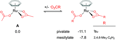 | ||
| Fig. 2 BP86-D3BJ(BS2,MeCN)//BP86(BS1) free energy values at 120 °C for carboxylate exchange at A in kcal mol−1. | ||
The arene
Coordination of the C2-symmetric p-cymene ligand (1-methyl-4-(propan-2-yl)benzene; para-Me-C6H4-iPr) to the Ru centre generates up to six conformers. To reduce computational cost and the amount of conformational space requiring exploration, benzene (C6H6) is a popular arene to include in the model instead. Exchanging benzene for bulkier arenes, such as toluene, o-xylene, p-cymene or hexa-methyl-benzene (Bn*), does lead to the Ru(II) bis acetate complex becoming more stable (see Fig. 3). Six conformers were computed for each non-C6 symmetric arene to find the best orientation of the arene to the Ru reaction centre. Conformers' free energies ranged from 0.3–1.5 kcal mol−1 relative to the lowest conformer. The most significant reduction is naturally for the bulkiest of the arenes – Bn*. However, this stabilisation seen in the relative energies of A when coordinating bulkier arenes would apply to all species that also had the bulkier arene coordinated. Essentially all of the p-cymene structures would be lowered by 3.5 kcal mol−1 – in comparison to a benzene equivalent computed structure. Therefore, relatively to each other within the p-cymene system the barriers and product stabilities would be similar to any benzene relative energies.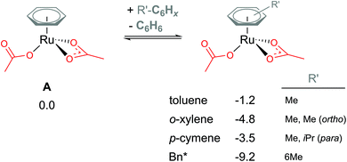 | ||
| Fig. 3 BP86-D3BJ(BS2,MeCN)//BP86(BS1) free energy values at 120 °C for arene exchange at A in kcal mol−1. | ||
Neutral vs. cationic C–H activation
Attempts to compare different charged complexes is often problematic when using DFT calculations. Only when applying solvation corrections to the energies of the structures do relative values appear more rational. For example, in Fig. 4, comparing the BP86(BS1) energy of B+ [(C6H6)Ru(a-H)(OAc)]+ to A [(C6H6)Ru(OAc)2] (cationic and neutral structures respectively) gives an energy difference of 113.5 kcal mol−1 – highly unrealistic. By computing a polarised continuum around each optimised molecule to mimic effects of acetonitrile solvation, the energy difference is lowered to 26.2 kcal mol−1 (BP86(BS1, MeCN)). Although this difference is still not perfect, as the free energy for formation of charges species (from neutral) is difficult to predict when using continuum solvation models that compensate the high energy required to dissociate the ions with large solvation free energies, thereby underestimating the solvation of a ion pair (cation and anion) in polar solvents like acetonitrile and methanol.29,30 It is only when combining Gibbs free energy with a thermal correction, a dispersion energy correction and a larger basis set energy that the value becomes 2.8 kcal mol−1. Missing any one of these methodology steps could lead to the rejection of cationic pathways as viable mechanistic pathways in a computational study.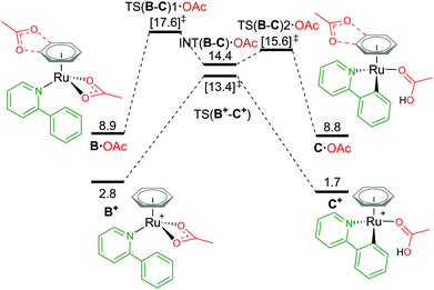 | ||
| Fig. 4 BP86-D3BJ(BS2,MeCN)//BP86(BS1) free energy values at 120 °C for C–H activation of a-H in species B+ and B·OAc relative to A, [(C6H6)Ru(OAc)2], in kcal mol−1. | ||
From the cationic B+ species, an one-step AMLA transition state gives a C–H activation barrier of 10.6 kcal mol−1, as the acetate binding mode changes from κ2 to κ1 and the C–H bond approaches the Ru(II) centre. Cleavage of the bond then results in the formation of C+, [(C6H6)Ru(a)(HOAc)] ΔGMeCN = +1.7 kcal mol−1, with the HO of the acetic acid ligand pointing parallel to the newly formed Ru–C bond. C+ is 1.1 kcal mol−1 more stable than the pre-activation B+ species. Reversing along this reaction coordinate gives a barrier of 11.7 kcal mol−1, in agreement with experimental studies that show kinetically C–H activation is reversible.31,32 Elongation of the C–H bond in the transition state structure shows an increase of only 0.024 Å, and would likely result in a small kinetic isotope effect observed under the correct experimental kinetic conditions.33
Alternatively, to negate the issues associated with energetically comparing a charged molecule to a neutral, placing the dissociated carboxylate anion close to the cationic species neutralises the overall charge of the structure, as B·OAc (Fig. 4). This “ion-pair” approach reviewed by Clot in 2009,34 does increase the conformational space that needs to be computationally explored to identify the most stable site for the anion (see ESI† for full details). Weak H-bond coordination of the oxygen atoms of the acetate to the benzene ring directly above the nitrogen atom of the coordinated a-H substrate is computed to have a ΔGMeCN of +8.9 kcal mol−1, which is over 2 kcal mol−1 more stable than other positions around the benzene ring and the substrate itself. This is also 6.1 kcal mol−1 higher in free energy than the cationic equivalent species B+.
Acetate assisted C–H activation from B·OAc proceeds by a two-step AMLA mechanism, with TS(B-C)1·OAc being the higher of the two transition states (TSs), giving an overall barrier of 8.7 kcal mol−1. This first AMLA TS involves the displacement of the acetate κ2 binding prior to the agostic intermediate formation of (INT(B-C)·OAc), and has been previously shown to be the higher TS for ruthenium systems.31 As such, a small kinetic isotope effect is anticipated as the C–H bond length has only elongated by 0.019 Å in this TS structure. Comparatively for TS(B-C)2·OAc, the C–H bond is more significantly elongated by 0.168 Å (relative to B·OAc), however, the energy of this TS is lower than the preceding barrier. Again, the reversibility of the C–H activation step is preserved using this approach, with B·OAc and C·OAc having the same free energy (to 1 decimal place). Ultimately, ion pairing the cationic Ru complex with the dissociated carboxylate does not stabilise the mechanistic pathway and in fact raises its free energy in contrast to the cationic pathway.
An alternative route to maintain the neutrality of the computed structures is to consider non-AMLA mechanisms, as shown in Fig. 5. Non-coordination of the substrate a-H to the Ru centre, gives a free energy of +3.6 kcal mol−1 (A·a-H, [(C6H6)Ru(OAc)2]·a-H). Attempts were made to find a “non-directed” C–H activation TS from this intermediate, as others have previously found for phenylpyrazole substrates and RhCp* complexes,32 but was unsuccessful. This is likely due to stronger Ru–O bonds in A in comparison to the equivalent Rh structure, where in the latter displacement of the κ2 acetate can occur more readily to attack either the ortho H of interest, or in fact any of the acidic substrate C–H bonds.
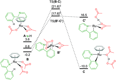 | ||
| Fig. 5 BP86-D3BJ(BS2,MeCN)//BP86(BS1) free energy values at 120 °C for C–H activation of a-H in species B and B′ relative to A, [(C6H6)Ru(OAc)2], in kcal mol−1. | ||
By not enforcing the loss of a carboxylate at the Ru(II) complex when the substrate coordinates, both acetate ligands are forced to bind in an κ1 fashion to give B, [(C6H6)Ru(a-H)(OAc)2]. Care should be taken here as there are four potential conformers for this species – all within 2–3 kcal mol−1 of each other. The distal oxygen of the acetate can point “up” towards the arene ring, or “down” tucking itself underneath the coordinated substrate. Here, the most stable conformer of B is with both acetates pointing “up” at −0.2 kcal mol−1. Activation of the C–H bond gives a barrier of 21.8 kcal mol−1, before irreversibly forming C, at −10.0 kcal mol−1. The product complex is stabilised by the dissociated acetic acid H-bonding to the remaining κ1 acetate coordinated at the Ru centre.
Finally, as mentioned in the introduction, the role of the arene co-ligand and whether it remains coordinated throughout the reaction process led Nelson et al. to suggest a new potential C–H activation pathway starting at B′,16 [Ru(a-H)(OAc)2] ΔGMeCN = +0.8 kcal mol−1. This pathway has no arene, but two κ2 coordinated acetate ligands. An AMLA κ2–κ1 displacement TS gives a one-step barrier of 16.8 kcal mol−1 and an elongation of the C–H bond by 0.043 Å (TS(B′-C′)). The resulting acetic acid complex, C′, lies only 1.1 kcal mol−1 below the TS, suggesting a very shallow energy surface on this side of the mechanism. Removal of the acetic acid from C′ lowers the energy of the complex by 3.1 kcal mol−1 to ΔGMeCN = +13.4 kcal mol−1. The endergonic product species are likely a result of the low coordination at the Ru(II) centre, and suggest that C′ would not be unsaturated at the metal centre for long, with either a functionalisation reagent or solvent molecule binding at available coordination sites.
In contrast to the values computed by Nelson et al.,16 in this study the relative value of B′ to A is over 10 kcal mol−1 more stable.35 However, relative barrier heights and product stability are similar in size. Whilst we have chosen to use the smaller benzene as our arene to avoid having to excessively map conformational space for the orientation of the arene to the Ru centre, Nelson chose to model the experimentally used (and bulkier) p-cymene. It would be prudent to imply that the steric pressure of an arene coordinated to a Ru centre would equally effect all species of that pathway as mentioned vide supra, hence similar barrier heights and product stabilities being observed.36 This relative energy difference between A and B/B′ can therefore not be attributed to arene choice alone, as our studies showed that [(p-cymene)Ru(OAc)2] is 3.5 kcal mol−1 more stable than the benzene equivalent of A, and this additional “3.5 kcal mol−1” stability would be included in all of the Nelson study's computed energy values. Therefore, the difference may be an artefact of how a-H alone was computed, or a result of study specific computational methodologies. Whilst the solvent used in the Nelson model was different (NMP), it has a similar dielectric constant to acetonitrile (εNMP = 32.6 vs. εMeCN = 35.7), especially in comparison to more apolar solvents such as toluene (εtol = 2.4). This leaves functional choice – M06//BP86-D3 compared to our BP86-D3(BJ)//BP86 approach as the potential source of the discrepancy.
Association of two substrate molecules
Following a similar theme of arene loss, and inspired by a C–H activation mechanistic study published by Macgregor and Larrosa,12 the coordination of two substrate molecules to the Ru centre (and the removal of the arene) was explored. As shown in Fig. 6, there are several associated structures for “D”, [Ru(a-H)2(OAc)2]. Coordination of both directing group substrates via their nitrogen atom, and continued coordination of two acetates (one κ2 bound, the other κ1) gives the stable species D; ΔGMeCN = −17.0 kcal mol−1. AMLA activation of one a-H C–H bond involves a barrier of 20.2 kcal mol−1, before forming the product complex E. This is endergonic to D by +9.3 kcal mol−1 due to the unusual coordination mode of the acetic acid. Removal of the acid from E gave a complex with ΔGMeCN = −19.0 kcal mol−1 – and this species is now 2.0 kcal mol−1 exergonic relative to D.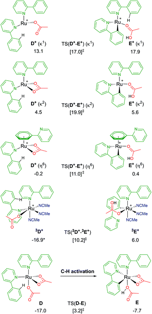 | ||
| Fig. 6 BP86-D3BJ(BS2,MeCN)//BP86(BS1) free energy values for C–H activation of a-H in species D, D+ and 3D+ relative to A, [(C6H6)Ru(OAc)2], in kcal mol−1. | ||
Loss of an acetate gives three isomers; D+ (κ2), D+ (κ1) and D+ (η6). The most stable geometry is the latter, at −0.2 kcal mol−1, and involves the loss of one Ru–N bond as the phenyl group of the second un-activated substrate occupies the traditional η6 position of an arene. Direct comparison of this with the equivalent B+ pathway sees the barrier for TS(D+-E+) (η6) a mere 0.6 kcal mol−1 higher. Both the κ2 and κ1 labelled D+ isomers have higher C–H activation transition states, and barriers relative to their associated D+ isomers of 15.4 and 3.9 kcal mol−1 respectively.37
The remaining D isomer is 3D+, leading us nicely to our next section of pathways. This six-coordinate isomer has two a-H substrates bound through their nitrogen atoms, one κ1 acetate and three additional acetonitrile solvent molecules. Entropy appears to have a large impact on the free energy of 3D+, ΔGMeCN = −16.9 kcal mol−1, 30 kcal mol−1 more stable than the equivalent D+ (κ1) isomer that also has an κ1 acetate ligand. The crowded metal centre means that a large C–H activation barrier of 27.1 kcal mol−1 was computed. However, an intermediate was isolated at −0.6 kcal mol−1 (before the transition state) that shows cleavage of the Ru–N bond of the substrate being activated, as the phenyl ring of a-H η2 binds to Ru to allow better distal oxygen atom CMD attack of the ortho C–H bond. The product complex, 3E+, relieves the steric pressure of a potential seven-coordinate Ru centre by only binding to the activated substrate at the newly cleaved carbon position, but the species is strongly exergonic by 22.9 kcal mol−1. Based on these preliminary investigations into multiple substrate coordination during the C–H activation process, there are two potential species for future consideration: D and D+ (η6).
Association of MeCN
Explicit modelling of solvent molecules in computational studies is rarely considered, as it can exponentially complicate an already complex reaction surface. Knowing that experimentally arene loss is a likely process,8,9 alternative coordination options at the metal centre should be explored. Hence, for the remainder of this study direct acetonitrile coordination at Ru is modelled. The reported results will help shape understanding of modelling explicit binding of solvent molecules at metal centres, and whether reaction energy barriers are lowered or raised.An exposed and semi-naked metal centre is unlikely to exist experimentally in solution. Computationally these species tend to be high in energy, for example the four-coordinate Ru complex C′ (ΔGMeCN = +16.5 kcal mol−1) vide spura. Therefore, how many solvent molecules would coordinate to a Ru centre in experimental conditions? What is the ligand ratio of acetate : acetonitrile : arene? As Fig. 7 highlights,38 multiple potential isomers underpin the complexity of explicit solvent modelling – before even considering the coordination of a substrate. Taking our relative zero complex A [(C6H6)Ru(OAc)2] and adding an acetonitrile ligand forces the benzene hapticity to decrease from η6 to η2, to accommodate the additional solvent coordination at Ru, and raising the energy of the geometry to +4.4 kcal mol−1 (1A).38 Loss of the κ1 acetate affords 1A+, with an increase in free energy of +8.7 kcal mol−1. Further loss of the remaining κ2 acetate and coordination of two acetonitrile molecules (3A2+) raises the energy further for this dicationic Ru structure to 23.9 kcal mol−1.
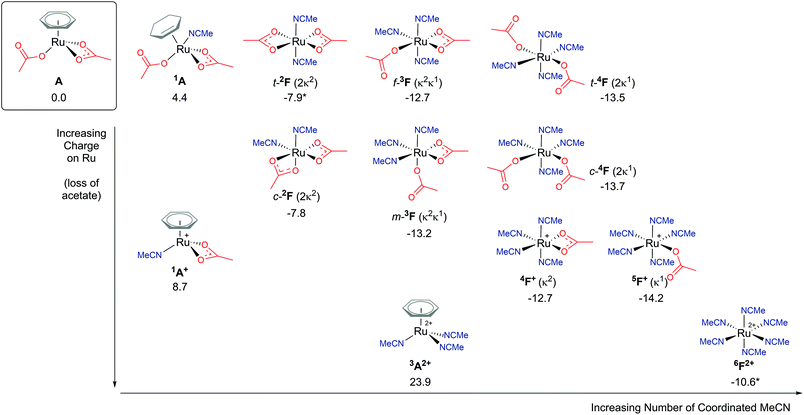 | ||
| Fig. 7 BP86-D3BJ(BS2,MeCN)//BP86(BS1) free energy values at 120 °C for isomers of solvent (MeCN) coordination to A, [(C6H6)Ru(OAc)2], in kcal mol−1. (Two species are denoted by *, 6F2+ and t-2F (2κ2), see ESI.†) | ||
Arene η6-coordination equates to three acetonitrile ligands, and for 6F2+ this ligand exchange lowers the stability of the [Ru(NCMe)6]2+ complex by 34.5 kcal mol−1. This highlights the incompatible nature of acetonitrile and arene coordination at a metal centre. Both complexes are dicationic, but the homoleptic 6F2+ is clearly preferred, despite being entropically disfavoured. Coordination of an acetate anion is achieved by displacing one (5F+ (κ1)) or two (5F+ (κ2)) acetonitrile ligands, resulting in a free energy change of −3.6 or −2.1 kcal mol−1 respectively.
The presence of two acetate anions at the Ru leads to three acetonitrile ligand ratios. Four solvent molecules would be coordinated if both acetates were bound in a κ1 fashion (4F), two solvent ligands would be present if both acetates were coordinated in a κ2 mode (2F), and three acetonitriles are possible if one of each of the acetates displayed κ1 and κ2 coordination (3F). For each of these geometries, cis/trans (c-/t- for 4F and 2F) and mer/fac (m-/f- for 3F) isomers are possible. The most stable of each of these F complexes are; t-2F (ΔGMeCN = −7.9 kcal mol−1), m-3F (ΔGMeCN = −13.2 kcal mol−1) and c-4F (ΔGMeCN = −13.7 kcal mol−1). The more acetonitrile solvent molecules coordinated to the Ru centre, the lower the free energy of that complex relative to A, with an approximate free energy cost in the region of 2–5 kcal mol−1 for changing the binding mode of the acetate from pendant (κ1) to chelating (κ2).
Coordination of a substrate exponentially increases the complexity of the reaction landscape. First, we shall consider only one acetonitrile molecule coordinating along the 1B+ pathway.39 An additional solvent ligand at the Ru centre forces the hapticity of the arene ligand again to decrease to η2. There are five potential isomers, as shown in Fig. 8, when considering the different combinations of bonding at the metal, ranging from 11.4–16.9 kcal mol−1 (relative to starting species A). In each 1B+ isomer, the acetate binds in a κ2 fashion, affording an AMLA C–H activation to occur, and most importantly a “vacant site” (VS) where the C–H bond can already begin to approach the Ru centre in an agostic fashion.
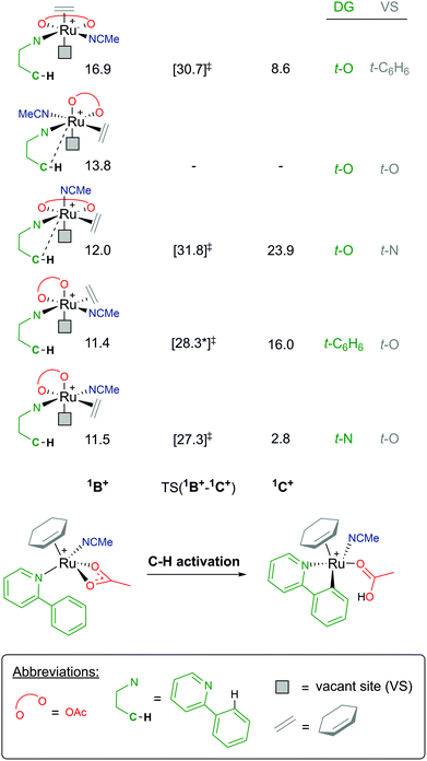 | ||
| Fig. 8 BP86-D3BJ(BS2,MeCN)//BP86(BS1) free energy values at 120 °C for C–H activation of a-H for isomers of 1B+, relative to A, [(C6H6)Ru(OAc)2], in kcal mol−1. | ||
As there are five unique coordinating sites at Ru, the isomers are identified by what ligand is trans to the directing group N and trans to the vacant site, which is where the new Ru–C bond will form. Barriers for C–H activation were in the region of 13.8–19.8 kcal mol−1 depending on the isomer, although a barrier for the 1B+ isomer at 13.8 kcal mol−1 was not successfully located. Of the four C–H activations optimised for this pathway, the favoured isomer has the substrate coordinated trans to the acetonitrile solvent and the new Ru–C position trans to one of the acetate oxygen atoms, with a barrier for 15.8 kcal mol−1, and affording the exergonic 1C+ product complex at +2.8 kcal mol−1. Overall, this pathway seems unlikely due to the high free energy of 1B+, and this is due to the crowded environment at the metal centre and the loss of arene ring hapticity.
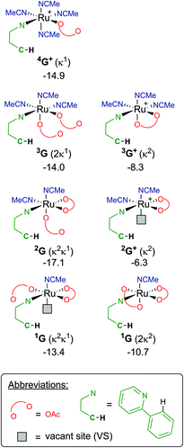
Finally, focusing on no arene coordinated at the Ru centre, but only the substrate (a-H), one/two acetates and a multiple of solvent ligands, results in seven potential “G” complexes – of which each have several isomers. The most stable free energies for each G are shown in Fig. 9, with 2G the lowest at −17.1 kcal mol−1, which has acetonitrile trans to the directing group and the κ1 acetate trans to the C–H activation site. These versions of G can form from F along multiple pathways, for example; either acetate loss from 3F or MeCN loss from 4F+ would give the same pre-activation complex 3G+.
Therefore, instead of an exhaustive multi-dimensional map, the authors have chosen to highlight the two more stable and most sensible pathways involving G, with the associated computed geometries shown in Fig. 10. Both pre-C–H activation complexes, 2G and 1G (κ2κ1) show agostic interactions between the Ru and C–H bond, elongating the latter to 1.21 and 1.22 Å respectively. The barriers for AMLA activation are considerably low, at just 2.9 and 1.6 kcal mol−1 for TS(2G-2H) and TS(1G-1H). These transition states are the first computed examples of AMLA activation of the C–H bond for a directing group substrate with acetonitrile replacing the typical arene co-ligand. The product intermediates show that activation at these species is in equilbirum (2H = −17.1 kcal mol−1) or exergonic (1H = −17.1 kcal mol−1). These lower barriers are an artefact of the preceding arene-free G complexes already being primed to activate the ortho C–H bond of the substrate. Greater thought and consideration should be given to these range of potential active species for any reaction that is carried out in a nitrile solvent or a solvent with similar polarity.
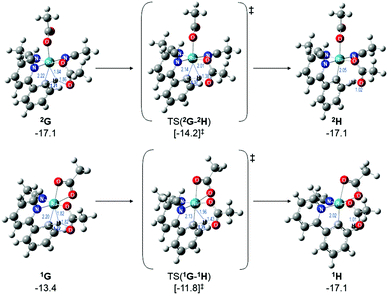 | ||
| Fig. 10 BP86-D3BJ(BS2,MeCN)//BP86(BS1) geometries and free energy values at 120 °C for C–H activation of a-H for isomers of 2G and 1G relative to A, [(C6H6)Ru(OAc)2], in Å and kcal mol−1. | ||
Conclusions
A variety of different AMLA pathways have been presented, where an κ2 acetate has cleaved a C–H bond. Few CMD processes were identified during the study, as the potential energy surface for an κ1 acetate dissociating and pulling away an acidic H atom is very flat and hence locating maxima along such a reaction coordinate is near impossible to achieve. The various different pathways attempted suggest that anion dissociation leading to B+ is important to create the space needed at the Ru(II) centre for the new Ru–C bond to coordinate, and would mimic experimental observations of C–H activation reversibility and barrier size. Although higher coordination numbers may initially stabilise the pre activation species, the cost is much larger barriers for activation and often highly endergonic product complexes. Exchange of the arene for another aromatic ring, such as an aromatic solvent molecule or part of the substrate, that would also η6 bind to the Ru should be considered when modelling in the future. This could also explain why when the pre-catalyst is arene-free C–H activation is still able to proceed.As with any reaction, it is completely plausible for more than one mechanism and pathway to be active at the same time. With the wide range of potential active Ru complexes that could facilitate C–H activation, careful consideration of all potential species is prudent. In particular for experiments in nitrile solvents, the identity of the active catalyst can diverge in to a wide range of solvent coordinated options that do not require an arene to be bound at Ru. Importantly, the results presented in this paper have been given for an acetonitrile solvation correction. The ESI† also provides the free energies for toluene solvation as well, where any cationic Ru species is significantly destabilised (by approximately 35 kcal mol−1) due to the apolar solvent's high energies for the dissociated carboxylate anion that are needed to balance the species relatively to the neutral starting complex A, [(arene)Ru(OAc)2]. Ultimately, we hope this study has given readers food for thought about the consequences of methodology choices when doing computational studies, and that any reaction landscape is littered with conformations and isomers, and limited only by what is speculated and built by the computational modeler.
Conflicts of interest
There are no conflicts to declare.Acknowledgements
Then authors acknowledge EPSRC (UK) for financial support under award EP/R020752/1 (CLM and NAR), and the University of Bath for undergraduate support (JSH). This research made use of the Balena High Performance Computing (HPC) Service at the University of Bath. The authors would like to thank Stuart Macgregor (Heriot-Watt University), Dai Davies (University of Leicester), Mike Hill (University of Bath) and many others for their discussions, guidance and encouragement that have facilitated this study.Notes and references
- L. Ackermann, Chem. Rev., 2011, 111, 1315–1345 CrossRef CAS PubMed.
- P. B. Arockiam, C. Bruneau and P. H. Dixneuf, Chem. Rev., 2012, 112, 5879–5918 CrossRef CAS PubMed.
- D. L. Davies, S. A. Macgregor and C. L. McMullin, Chem. Rev., 2017, 117, 8649–8709 CrossRef CAS PubMed.
- C. Shan, L. Zhu, L.-B. Qu, R. Bai and Y. Lan, Chem. Soc. Rev., 2018, 47, 7552–7576 RSC.
- K. J. T. Carr, S. A. Macgregor and C. L. McMullin, in C-H Bond Activation and Catalytic Functionalization I, ed. P. H. Dixneuf and H. Doucet, Springer International Publishing, Cham, 2016, pp. 53–76 Search PubMed.
- R. A. Alharis, C. L. McMullin, D. L. Davies, K. Singh and S. A. Macgregor, J. Am. Chem. Soc., 2019, 141(22), 8896–8906 CrossRef CAS PubMed.
- H. H. Al Mamari, E. Diers and L. Ackermann, Chem. – Eur. J., 2014, 20, 9739–9743 CrossRef CAS PubMed.
- M. Simonetti, G. J. P. Perry, X. C. Cambeiro, F. Juliá-Hernández, J. N. Arokianathar and I. Larrosa, J. Am. Chem. Soc., 2016, 138, 3596–3606 CrossRef CAS PubMed.
- P. Marcé, A. J. Paterson, M. F. Mahon and C. G. Frost, Catal. Sci. Technol., 2016, 6, 7068–7076 RSC.
- S. Fernandez, M. Pfeffer, V. Ritleng and C. Sirlin, Organometallics, 1999, 18, 2390–2394 CrossRef CAS.
- E. Ferrer Flegeau, C. Bruneau, P. H. Dixneuf and A. Jutand, J. Am. Chem. Soc., 2011, 133, 10161–10170 CrossRef PubMed.
- M. Simonetti, R. Kuniyil, S. A. Macgregor and I. Larrosa, J. Am. Chem. Soc., 2018, 140, 11836–11847 CrossRef CAS PubMed.
- C. R. Groom, I. J. Bruno, M. P. Lightfoot and S. C. Ward, Acta Crystallogr., Sect. B: Struct. Sci., Cryst. Eng. Mater., 2016, 72, 171–179 CrossRef CAS PubMed.
- A. D. Ryabov, R. Le Lagadec, H. Estevez, R. A. Toscano, S. Hernandez, L. Alexandrova, V. S. Kurova, A. Fischer, C. Sirlin and M. Pfeffer, Inorg. Chem., 2005, 44, 1626–1634 CrossRef CAS PubMed.
- Crystal structures TAVNOV, TADSUO, FAVWIK, URICUU were of the form [(p-cymene)Ru(O2CR)2] for different carboxylates. OMATUR and XIYDOA are [(arene)Ru(OAc)Cl] structures with different arene ligands, and PALBIP is a crystal structure of [(p-cymene)Ru(OAc)(P)] where (P) is a phosphine ligand.
- J. McIntyre, I. Mayoral-Soler, P. Salvador, A. Poater and D. J. Nelson, Catal. Sci. Technol., 2018, 8, 3174–3182 RSC.
- L. Perrin, K. J. T. Carr, D. McKay, C. L. McMullin, S. A. Macgregor and O. Eisenstein, in Computational Studies in Organometallic Chemistry, ed. S. A. Macgregor and O. Eisenstein, Springer International Publishing, Cham, 2016, pp. 1–37, DOI:10.1007/430_2015_176.
- As these mechanisms involve agostic interactions and intermediates the choice of DFT functional can be critical as B3LYP and others fail to optimise such geometries as minima. In contrast, BP86 has repeatedly shown it is capable of isolating such agostic species as minima.
- Gaussian 09 Search PubMed.
- D. Andrae, U. Häußermann, M. Dolg, H. Stoll and H. Preuß, Theor. Chim. Acta, 1990, 77, 123–141 CrossRef CAS.
- P. C. Hariharan and J. A. Pople, Theor. Chim. Acta, 1973, 28, 213–222 CrossRef CAS.
- W. J. Hehre, R. Ditchfield and J. A. Pople, J. Chem. Phys., 1972, 56, 2257–2261 CrossRef CAS.
- A. D. Becke, Phys. Rev. A, 1988, 38, 3098–3100 CrossRef CAS.
- J. P. Perdew, Phys. Rev. B: Condens. Matter Mater. Phys., 1986, 33, 8822–8824 CrossRef PubMed.
- J. Tomasi, B. Mennucci and R. Cammi, Chem. Rev., 2005, 105, 2999–3094 CrossRef CAS PubMed.
- S. Grimme, S. Ehrlich and L. Goerigk, J. Comput. Chem., 2011, 32, 1456–1465 CrossRef CAS PubMed.
- A. Holtzer, Biopolymers, 1995, 35, 595–602 CrossRef CAS PubMed.
- C. L. McMullin, J. Jover, J. N. Harvey and N. Fey, Dalton Trans., 2010, 39, 10833–10836 RSC.
- N. M. Silva, P. Deglmann and J. R. Pliego, J. Phys. Chem. B, 2016, 120, 12660–12668 CrossRef CAS PubMed.
- E. Miguel, C. Santos, C. Silva and J. Pliego Jr., J. Braz. Chem. Soc., 2016, 27, 2055–2061 CAS.
- A. G. Algarra, W. B. Cross, D. L. Davies, Q. Khamker, S. A. Macgregor, C. L. McMullin and K. Singh, J. Org. Chem., 2014, 79, 1954–1970 CrossRef CAS PubMed.
- D. L. Davies, C. E. Ellul, S. A. Macgregor, C. L. McMullin and K. Singh, J. Am. Chem. Soc., 2015, 137, 9659–9669 CrossRef CAS PubMed.
- E. M. Simmons and J. F. Hartwig, Angew. Chem., Int. Ed., 2012, 51, 3066–3072 CrossRef CAS PubMed.
- E. Clot, Eur. J. Inorg. Chem., 2009, 2319–2328 CrossRef CAS.
- Nelson's reported values for B and B′ were 11.5 and 14.8 kcal mol−1 respectively using their reported methodology.
- In fact applying our full methodology to the Nelson's study p-cymene geometries for B, TS(B-C) and C gave free energies of −3.8, 14.6 and −15.0 kcal mol−1 respectively. Nelson et al. reported values of 11.5, 31.3 and 2.8 kcal mol−1 respectively for the geometries using their methodology. The reason behind these energy differences are unknown and highlight the subtlies of each individual computational methodology.
- Note: the higher than its TS free energy value of E+ (κ1) is a result of the Ru-coordinated oxygen atom interacting with one of the co-ligand substrate's ortho hydrogen atom.
- Note: labelling of the different isomers is such that the preceeding superscript number represents the number of acetonitrile ligands coordinated, the letter whether arene is present (A) or not (F), and the suffix superscript determines whether two (2+), one (+) or no acetates have been dissociated.
- For the DG t-C6H6/VS t-O isomer at 11.4 kcal mol−1 C–H activation is a two-step process, the higher barrier and TS(1B+-1C+)1 is quoted at 28.3 kcal mol−1, with the subsequent agostic intermediate at +22.1 kcal mol−1 and the second (and shallow) TS(1B+-1C+)2 at +23.1 kcal mol−1.
Footnote |
| † Electronic supplementary information (ESI) available: xyz coordinates for all computed structures and associated energies. See DOI: 10.1039/c9ob01092k |
| This journal is © The Royal Society of Chemistry 2019 |

