
 Open Access Article
 This Open Access Article is licensed under a
 Creative Commons Attribution 3.0 Unported Licence
Anisotropic buckling of few-layer black phosphorus†
Luis
Vaquero-Garzon
,
Riccardo
Frisenda
 * and
Andres
Castellanos-Gomez
*
* and
Andres
Castellanos-Gomez
*
Materials Science Factory, Instituto de Ciencia de Materiales de Madrid (ICMM-CSIC), Madrid, E-28049, Spain. E-mail: riccardo.frisenda@csic.es; andres.castellanos@csic.es
First published on 4th June 2019
Abstract
When a two-dimensional material, adhered onto a compliant substrate, is subjected to compression it can undergo a buckling instability yielding to a periodic rippling. Interestingly, when black phosphorus (bP) flakes are compressed along the zig-zag crystal direction, the flake buckles forming ripples with a 40% longer period than that obtained when the compression is applied along the armchair direction. This anisotropic buckling stems from the puckered honeycomb crystal structure of bP and a quantitative analysis of the ripple period allows the determination of the Youngs's modulus of few-layer bP along the armchair direction (EbP_AC = 35.1 ± 6.3 GPa) and the zig-zag direction (EbP_ZZ = 93.3 ± 21.8 GPa).
Since its isolation in 2014,1–6 few-layer black phosphorus (bP) keeps attracting the interest of the scientific community because of its remarkable electronic properties, (i.e., ultrahigh charge carrier mobility, ambipolar field effect, and so on)7–10 and optical properties (i.e., narrow direct gap, strong quantum confinement effect, large band gap electrical tunability, and so on)11–20 that has motivated its application in many electronic and optoelectronic devices.5,21–23 Strikingly, although the electronic and optical properties have been thoroughly characterized, its mechanical properties, which have a crucial role in its applicability in flexible electronics and nanoelectromechanical systems, have been barely studied experimentally and the research that has been done does not provide a good consensus in their results, especially in the value of the elastic modulus of the bP along the zig-zag (ZZ) direction.24–28 One possible explanation for the disagreement of the results in the literature is the environmental instability of bP: few-layer bP flakes degrade upon atmospheric exposure within hours.29–38 Favron et al. and Zhou et al. have deduced that the degradation is most likely to occur as a result of photo-induced oxidation, forming phosphorus oxide species, from oxygen absorbed in the accumulated water at the surface of exfoliated flakes exposed to ambient conditions.32,39,40 In the previous works, the mechanical testing methods used required exposing the flakes to air for relatively long periods of time and in some cases the studied flakes were even subjected to several wet chemistry microfabrication steps28 or exposed to electron beam irradiation.24 Therefore, there is a need for a technique that allows the study of the intrinsic mechanical properties of the pristine bP flakes immediately after their exfoliation.
In the research reported here, the mechanical properties of few-layer bP flakes have been studied using buckling induced metrology,41 which has been recently demonstrated to be a very fast and reliable way to measure the Young's modulus of thin films,41–43 organic semiconductors44 and two-dimensional (2D) materials.45–49 Interestingly, when the bP flakes are subjected to uniaxial compression, they tend to buckle forming ripples which predominantly run parallel to the ZZ crystal axis of the bP lattice, allowing the determination of the Young's modulus along the armchair (AC) direction. Then, we performed control experiments where the same bP flake was compressed along the AC and ZZ directions and it was found that, when compressed along the ZZ direction, the flake buckles forming ripples with a period about 1.4 times longer than that obtained for compression along the AC direction. Note that in previous buckling metrology measurements on other 2D materials, such as graphene or transition metal dichalcogenides, the controlled compression aligned along well-defined crystal directions were not reported. A quantitative analysis of the bP buckling allowed the determination of the Youngs's modulus of few-layer bP along the AC direction (EbP_AC = 35.1 ± 6.3 GPa) and the ZZ direction (EbP_ZZ = 93.3 ± 21.8 GPa).
The bP flakes are buckled by transferring them onto a compliant elastomeric substrate that had been initially stretched. After transferring the flake the substrate pre-stress is released exerting a uniaxial compression on the bP flakes. As elastomeric material Gel-Film (WF X4 6.0 mil, Gel-Pak) was used and the pre-stress was applied by bending it (see Fig. 1a). The bP flakes are exfoliated from bulk bP crystals (HQ Graphene, The Netherlands) with Nitto 224SPV tape (Nitto Denko Corp.) and directly transferred onto the surface of the stretched Gel-Film substrate. After the transfer of the bP flake, the stress was released by unbending the Gel-Film substrate, and the sample was inspected under an optical microscope to find the buckled bP flakes. Fig. 1b shows a transmission mode optical microscopy image of a few-layer bP flake displaying a clear periodic ripple pattern that arises from the interplay between the flake buckling and the flake–substrate adhesion interaction.
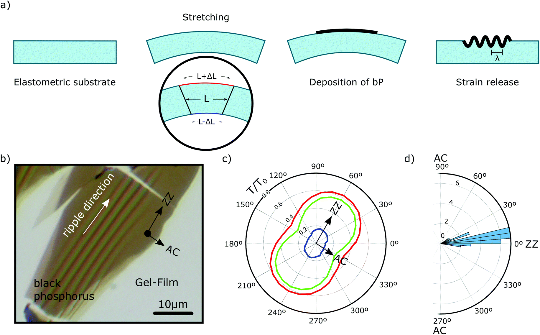 | ||
| Fig. 1 (a) Schematic diagram of the process used to fabricate the samples, where the flakes are transferred onto a stretched elastomeric substrate. When the stress is released, the flakes are subjected to compressive stress that produces ripples with a certain thickness dependent period. (b) Transmission mode optical microscopy images of a bP multilayer flake after releasing the stress on the elastomeric substrate, where the ripples are (almost) parallel to the ZZ direction shown in (c). (c) Angular dependence of the optical transmission measured on a bP flake normalized to the transmission of the substrate, by varying the angle of the linearly polarized illumination and where each color corresponds to the different channels (red, green and blue). The maximum value corresponds to the ZZ direction and the minimum to the AC direction. (d) Histogram of the difference between the angle of the ZZ and ripple directions for various samples. | ||
Using a (linear) polarization analyser during the optical microscopy inspection it is easy to determine the crystal orientation of the flakes because of the strong linear dichroism of bP. The optical transmittance of bP is larger for light linearly polarized along the ZZ crystal direction.50–53Fig. 1c shows the dependence of the red, green and blue image channels transmittance (calculated as the light intensity transmitted though the bP flake divided by the light intensity transmitted though the bare substrate) as a function of the angle between the linear polarizer direction and the horizontal axis (i.e., 0° represents polarization parallel to the horizontal axis and 90° represents polarization parallel to the vertical axis). The angular dependence of the transmittance follows Malus’ law [T ∝ cos2(θ + δθ)] as expected for a material with a strong linear dichroism. From the angle values where the transmittance reaches the maximum and the minimum, the ZZ and AC directions of the bP flake can be determined, respectively. These directions are displayed in Fig. 1b making it possible to determine the relative orientation of the ripples with respect to the crystalline directions. The ripples are oriented almost parallel to the ZZ crystal orientation.
According to theoretical calculations, the Young's modulus of bP was expected to be 3–4 times larger along the ZZ axis than along the AC axis54–57 and thus, it should be energetically favourable to bend the bP lattice along the ZZ axis. Furthermore, a lower Young's modulus along the AC direction also means that the compression stress needed to buckle the bP along that direction should also be lower than that needed to buckle it along the ZZ direction.42,43,58 These reasons explain why the bP flakes preferentially buckle with ripples parallel to the ZZ direction. Fig. 1c presents a polar histogram of the relative angle between the ZZ direction and the ripple orientation where a marked preferential alignment along the ZZ direction is seen.
Because of the preferential alignment of the ripples parallel to the ZZ direction, the Young's modulus of bP along the AC direction can be determined using a quantitative analysis of the buckling induced rippling period for bP flakes with different thicknesses. In fact, there is a linear relationship between the ripple period and the flake thickness which is given by:42,43,58
 | (1) |
 | (2) |
Fig. 2a shows four examples of rippled flakes with different thicknesses (ranging from 9 nm to 23 nm) that display a marked thickness dependent period of ripple. The thickness of the flakes was determined using quantitative analysis of the transmission mode optical images of the flakes (see Fig. S1 and S2 in the ESI† for details about the thickness determination procedure). As the whole measurement was carried out using optical microscopy, both the thickness of the flakes and the period of the ripples can be determined very quickly immediately after the exfoliation of bP (samples were exposed to air for less than 30–45 min from their exfoliation to their full experimental characterization) ensuring that this method provided the mechanical properties of pristine (not environmentally degraded bP). Note that in previous works on the mechanical properties of bP, the studied flakes were exposed to air for longer periods (AFM was used to locate the flakes and to make force indentation measurements)24,25,28 and in some cases the flakes were even subjected to several wet chemistry steps or electron beam irradiation (involved in the fabrication of freely suspended bP beams).24,28 Further information is given in the ESI† about a study on the role of environmental exposure on the buckling (and its in-plane anisotropy) of bP (Fig. S3 and S4†).
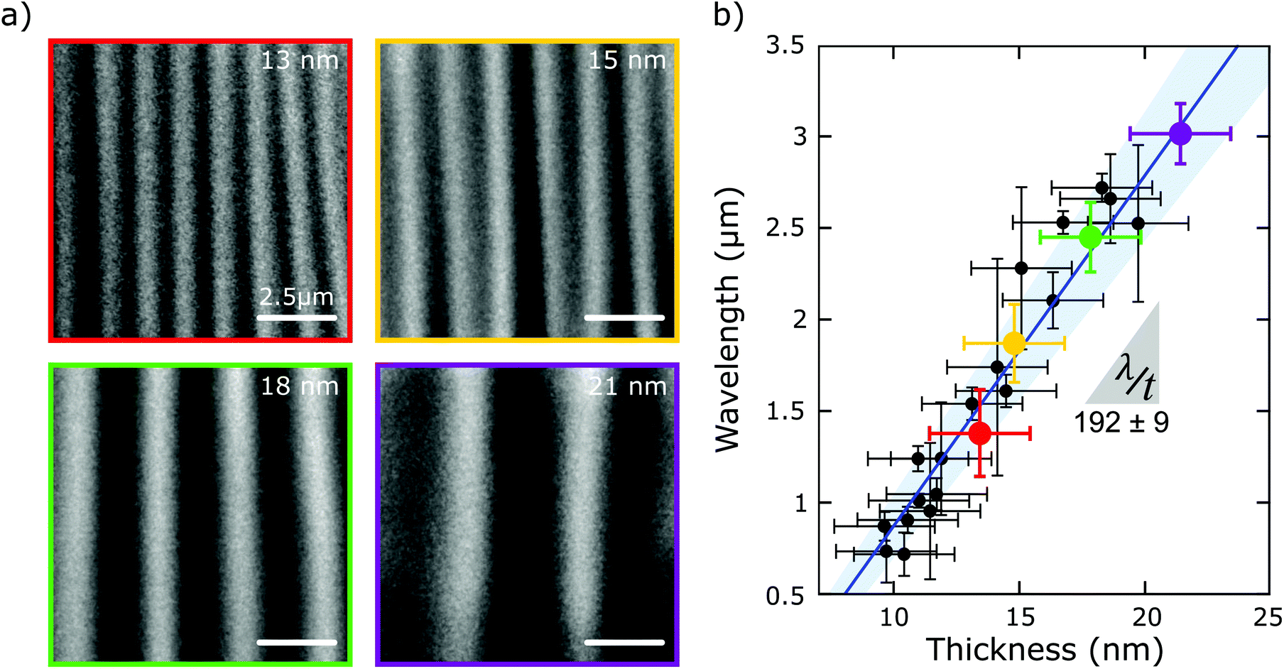 | ||
| Fig. 2 (a) Optical microscopy images of ripples with different periods for four bP flakes of different thickness. (b) Wavelength versus thickness graph for several bP flakes with different thickness, their error bars with 95% confidence curves. The solid blue line is the linear fit and the shaded area around the line indicates the uncertainty of the fit (95% confidence). | ||
Fig. 2b summarizes the results, acquired for 22 flakes with thicknesses ranging 9 nm to 23 nm, that followed a linear relationship with a slope of 192 ± 9 from which the Young's modulus could be determined along the AC direction: EbP_AC = 35.1 ± 6.3 GPa.
In order to gain an insight about the bP anisotropic mechanical properties, bP flakes were transferred onto a flat (unstrained) Gel-Film substrate, and their thickness and crystal orientation were determined using optical microscopy (as detailed previously) and the same flakes were subjected to compressive strain along the AC and ZZ directions by pinching the surface of the Gel-Film with two glass slides as illustrated in Fig. 3a. The Gel-Film substrate was compressed until the bP flake just started to buckle and further compression was stopped at that point (the approximate compression value was ∼10%). It is worth noting that because of the large Young's modulus mismatch between the Gel-Film and bP this compression would translate into a much lower compressive strain on the flake. Flakes with relatively large areas (∼4000 μm2) with homogeneous thickness were selected for this experiment to facilitate the analysis. Fig. 3b shows an example where the same flake was subjected to compressive strain along the AC and ZZ directions yielding an almost perpendicular ripple pattern with a sizeable different period (see the comparison between the two line profiles, for strain along the ZZ and AC directions, in Fig. 3c). Fig. 3d summarizes the measured period in five different flakes upon compression along the ZZ and AC directions. Using eqn (2), the Young's modulus of bP along the ZZ direction can be determined from the Young's modulus value along the AC direction and the ratio between the ripple period for compression along the AC and ZZ directions (λAC/λZZ = 1.39 ± 0.15):
 | (3) |
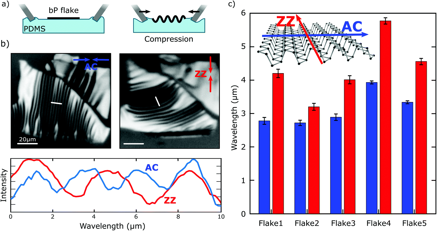 | ||
| Fig. 3 (a) Process of ripple formation in the two directions (ZZ and AC) using two manipulators, in a controlled way, to apply the compression along both directions. (b) Optical microscopy images of bP compressed in both directions. The period of the ripple pattern size depends on the direction where the compression is applied. The coloured arrows indicate the ZZ (blue) and AC (red) compression directions. (c) Comparison between the ZZ and AC ripple period measured for different flakes. | ||
The value obtained for EbP_ZZ was 93.3 ± 21.8 GPa. Note that the Young's modulus and the Poisson's ratio values along the ZZ and AC directions are interrelated in the following form EbP_ZZ·νbP_AC ≈ EbP_AC·νbP_ZZ, as expected from the symmetries of the compliance/stiffness tensor in the strain versus stress relationship.
In order to compare the results of the present research with the results reported previously in the literature, Table 1 shows a summary of both theoretical and experimental results from the literature. The Young's modulus value along the AC direction from this research was in a good agreement with the theoretical values reported in the literature that were between 21–52 GPa.54–56,61,62 However, the range of the theoretical values of the Young's modulus along the ZZ direction was much larger at 91–192 GPa. The experimental Young's modulus for the ZZ direction from this research is compatible with the lower values of these theoretical works.54–56 Looking at the previously reported experimental work, it is noted that in ref. 25 and 27 the measurements were carried out using AFM indentation on circular drumheads, and therefore, it was not possible to probe the direction dependence of the Young's modulus. In ref. 24 and 28, the measurements were carried out using AFM indentation on freely suspended, doubly clamped beams which allowed the determination of the Young's modulus along the AC and ZZ directions. In those works,24,28 however, the reported values (EbP_AC ∼ 27 GPa and EbP_ZZ ∼ 58–65 GPa) were noticeably lower than the values obtained in the current research. It must be noted that in those previous works, during the fabrication of the freely suspended beams the bP flakes were exposed to several steps of wet-chemistry and/or electron beam exposure which could effectively induce the degradation of bP, thus affecting their mechanical properties. As an alternative to the nanoindentation research, a recent work determined the Young's modulus of a 95 nm thick bP of a circular drumhead mechanical resonator by comparing the frequencies and mode shapes of high order mechanical resonances.26 Interestingly, this nanomechanical resonator measurement on a 95 nm thick bP flake provided Young's modulus values (EbP_AC ∼ 46 GPa and EbP_ZZ ∼ 116 GPa) which were close to the results of the current research (obtained using a buckling-metrology method) for 9–23 nm thick flakes. Furthermore, among the experimental results on few-layer bP the one in ref. 26 and our results based on the buckling metrology method, are ones which provided values for Young's modulus closer to those obtained using ultrasound velocity measurements in bulk bP crystals (EbP_AC ∼ 55 GPa and EbP_ZZ ∼ 179 GPa). Fig. 4 shows a graphical comparison between the different reported values of Young's modulus and the experimental values obtained in the current study.
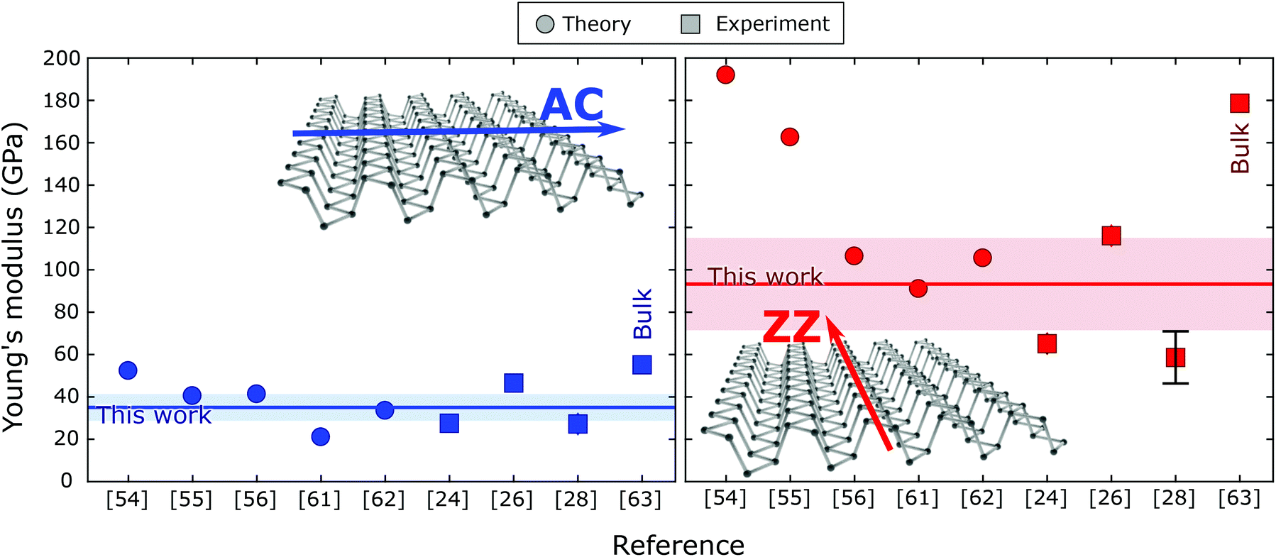 | ||
| Fig. 4 Graphical comparison between the reported theoretical and experimental values of the Young's modulus in the literature (symbols) and the experimental results from the current study (solid horizontal lines, the shaded area indicates the uncertainty). The values along the AC direction are displayed on the left and along the ZZ on the right. | ||
| Method and conditions (environment, thickness) | E [GPa] | Ref. | |||
|---|---|---|---|---|---|
| AC | ZZ | ||||
| a This experimental measurement did not allow resolution of the Young's modulus for different crystal orientations. | |||||
| Theory | Density functional theory | 41.3 | 106.4 | 56 | |
| Density functional theory | 37–44 | 159–166 | 55 | ||
| Density functional theory | 52.3 | 191.9 | 54 | ||
| Molecular dynamics | 21 | 91 | 61 | ||
| Molecular dynamics | 33.5 | 105.5 | 62 | ||
| Experiment | AFM indentation | Air, 15–25 nm | 27.2 ± 4.1 | 58.6 ± 11.7 | 28 |
| AFM indentation | High vacuum, 4–30 nm | 46 ± 10a | 27 | ||
| Nanomechanical resonators | Air, 95 nm | 46.5 ± 0.8 | 116.1 ± 1.9 | 26 | |
| AFM indentation | Air, 14–34 nm | 89.7 ± 26.4 to 276 ± 32.4a | 25 | ||
| AFM indentation | Air, 58–151 nm | 27.38 ± 2.35 | 65.16 ± 4.45 | 24 | |
| Ultrasound velocity | Air, bulk | 55.1 | 178.6 | 63 | |
| Buckling-metrology | Air, 9–23 nm | 35.1 ± 6.3 | 93.3 ± 21.8 | This work | |
Conclusions
In summary, few-layer bP flakes, deposited onto compliant elastomeric substrates, were subjected to uniaxial compressive strain yielding their buckling and inducing a periodic rippling. The quantitative analysis of the period of the ripples for flakes of different thickness allowed the determination of the Young's modulus of bP along the AC and ZZ directions: EbP_AC = 35.1 ± 6.3 GPa and EbP_ZZ = 93.3 ± 21.8 GPa. These results provide experimental evidence of the in-plane anisotropy of the intrinsic mechanical properties of pristine bP as the samples were exposed to air for less than 30–45 min, thus, preventing their environmental degradation.Experimental
Materials
The bP samples were prepared from a bulk crystal (HQ Graphene) using mechanical exfoliation with Nitto 224SPV tape (Nitto Denko). The elastomer substrate used in this work is a commercially available poly(dimethylsiloxane) (PDMS)-based substrate, Gel-Film WF X4 6.0 mil (Gel-Pak).Determination of the Young's modulus of the Gel-Film substrate
The Young's modulus of the elastomeric substrate was previously determined using force versus elongation experiments (see the ESI of ref. 45).Optical microscopy
Optical microscopy images were acquired using an AmScope BA MET310-T upright metallurgical microscope equipped with an AmScope 18 megapixels MU1803 camera. The calibration of the optical magnification system was carried out using imaging standard samples: one CD, one DVD, one DVD-R, and two diffraction gratings with 300 lines per mm (GR13-0305, Thorlabs) and 600 lines per mm (GR13-0605, Thorlabs).Image analysis
The quantitative analysis of the transmittance of the flakes and the rippling wavelength was carried out using Gwyddion software.64Thickness determination
The thickness determination was carried out by extracting the transmittance of the red, green and blue channels of the transmission mode optical microscopy images and comparing them with reference (not buckled) samples. See the ESI† for more details.Atomic force microscopy
Atomic force microscopy (AFM) measurements were made using an ezAFM from NanoMagnetics Instruments operated in tapping mode with cantilevers of 40 N m−1 and a resonance frequency of 300 kHz.Conflicts of interest
There are no conflicts to declare.Acknowledgements
This project has received funding from the European Research Council (ERC) under the European Union's Horizon 2020 research and innovation programme (Grant agreement no. 755655, ERC-StG 2017 project 2D-TOPSENSE). RF acknowledges support from the Spanish Ministry of Economy, Industry and Competitiveness through a Juan de la Cierva Formación fellowship (2017 FJCI-2017-32919). We acknowledge support of the publication fee by the CSIC Open Access Publication Support Initiative through its Unit of Information Resources for Research (URICI).References
- L. Li, Y. Yu, G. J. Ye, Q. Ge, X. Ou, H. Wu, D. Feng, X. H. Chen and Y. Zhang, Nat. Nanotechnol., 2014, 9, 372–377 CrossRef CAS PubMed.
- F. Xia, H. Wang and Y. Jia, Nat. Commun., 2014, 5, 4458 CrossRef CAS PubMed.
- H. Liu, A. T. Neal, Z. Zhu, Z. Luo, X. Xu, D. Tománek and P. D. Ye, ACS Nano, 2014, 8, 4033–4041 CrossRef CAS PubMed.
- A. Castellanos-Gomez, L. Vicarelli, E. Prada, J. O. Island, K. L. Narasimha-Acharya, S. I. Blanter, D. J. Groenendijk, M. Buscema, G. A. Steele, J. V. Alvarez, H. W. Zandbergen, J. J. Palacios and H. S. J. van der Zant, 2D Mater., 2014, 1, 025001 CrossRef.
- M. Buscema, D. J. Groenendijk, S. I. Blanter, G. A. Steele, H. S. J. van der Zant and A. Castellanos-Gomez, Nano Lett., 2014, 14, 3347–3352 CrossRef CAS PubMed.
- S. P. Koenig, R. A. Doganov, H. Schmidt, A. H. Castro Neto and B. Özyilmaz, Appl. Phys. Lett., 2014, 104, 103106 CrossRef.
- J. Qiao, X. Kong, Z.-X. Hu, F. Yang and W. Ji, Nat. Commun., 2014, 5, 4475 CrossRef CAS PubMed.
- N. Gillgren, D. Wickramaratne, Y. Shi, T. Espiritu, J. Yang, J. Hu, J. Wei, X. Liu, Z. Mao, K. Watanabe, T. Taniguchi, M. Bockrath, Y. Barlas, R. K. Lake and C. Ning Lau, 2D Mater., 2014, 2, 011001 CrossRef.
- L. Li, F. Yang, G. J. Ye, Z. Zhang, Z. Zhu, W.-K. Lou, X. Zhou, L. Li, K. Watanabe, T. Taniguchi, K. Chang, Y. Wang, X. H. Chen and Y. Zhang, Nat. Nanotechnol., 2016, 11, 593–597 CrossRef CAS PubMed.
- V. Tayari, N. Hemsworth, I. Fakih, A. Favron, E. Gaufrès, G. Gervais, R. Martel and T. Szkopek, Nat. Commun., 2015, 6, 7702 CrossRef CAS PubMed.
- L. Li, J. Kim, C. Jin, G. J. Ye, D. Y. Qiu, H. Felipe, Z. Shi, L. Chen, Z. Zhang and F. Yang, Nat. Nanotechnol., 2017, 12, 21 CrossRef CAS PubMed.
- A. Surrente, A. A. Mitioglu, K. Galkowski, W. Tabis, D. K. Maude and P. Plochocka, Phys. Rev. B: Condens. Matter Mater. Phys., 2016, 93, 121405 CrossRef.
- R. Xu, S. Zhang, F. Wang, J. Yang, Z. Wang, J. Pei, Y. W. Myint, B. Xing, Z. Yu and L. Fu, ACS Nano, 2016, 10, 2046–2053 CrossRef CAS PubMed.
- S. Zhang, J. Yang, R. Xu, F. Wang, W. Li, M. Ghufran, Y.-W. Zhang, Z. Yu, G. Zhang, Q. Qin and Y. Lu, ACS Nano, 2014, 8, 9590–9596 CrossRef CAS PubMed.
- X. Wang, A. M. Jones, K. L. Seyler, V. Tran, Y. Jia, H. Zhao, H. Wang, L. Yang, X. Xu and F. Xia, Nat. Nanotechnol., 2015, 10, 517–521 CrossRef CAS PubMed.
- H. Liu, Y. Du, Y. Deng and P. D. Ye, Chem. Soc. Rev., 2015, 44, 2732–2743 RSC.
- X. Ling, H. Wang, S. Huang, F. Xia and M. S. Dresselhaus, Proc. Natl. Acad. Sci. U. S. A., 2015, 112, 201416581 Search PubMed.
- A. Castellanos-Gomez, J. Phys. Chem. Lett., 2015, 6, 4280–4291 CrossRef CAS PubMed.
- R. Roldán and A. Castellanos-Gomez, Nat. Photonics, 2017, 11, 407–409 CrossRef.
- B. Deng, R. Frisenda, C. Li, X. Chen, A. Castellanos-Gomez and F. Xia, Adv. Opt. Mater., 2018, 6(19), 1800365 CrossRef.
- M. Buscema, D. J. Groenendijk, G. A. Steele, H. S. J. van der Zant and A. Castellanos-Gomez, Nat. Commun., 2014, 5, 4651 CrossRef CAS PubMed.
- Y. Deng, Z. Luo, N. J. Conrad, H. Liu, Y. Gong, S. Najmaei, P. M. Ajayan, J. Lou, X. Xu and P. D. Ye, ACS Nano, 2014, 8, 8292–8299 CrossRef CAS PubMed.
- H. Yuan, X. Liu, F. Afshinmanesh, W. Li, G. Xu, J. Sun, B. Lian, G. Ye, Y. Hikita, Z. Shen, S.-C. Zhang, X. Chen, M. Brongersma, H. Y. Hwang and Y. Cui, Nat. Nanotechnol., 2015, 10, 707–713 CrossRef CAS PubMed.
- H. Chen, P. Huang, D. Guo and G. Xie, J. Phys. Chem. C, 2016, 120, 29491–29497 CrossRef CAS.
- J.-Y. Wang, Y. Li, Z.-Y. Zhan, T. Li, L. Zhen and C.-Y. Xu, Appl. Phys. Lett., 2016, 108, 13104 CrossRef.
- Z. Wang, H. Jia, X.-Q. Zheng, R. Yang, G. J. Ye, X. H. Chen and P. X.-L. Feng, Nano Lett., 2016, 16, 5394–5400 CrossRef CAS PubMed.
- M. Moreno-Moreno, G. Lopez-Polin, A. Castellanos-Gomez, C. Gomez-Navarro and J. Gomez-Herrero, 2D Mater., 2016, 3, 031007 CrossRef.
- J. Tao, W. Shen, S. Wu, L. Liu, Z. Feng, C. Wang, C. Hu, P. Yao, H. Zhang, W. Pang, X. Duan, J. Liu, C. Zhou and D. Zhang, ACS Nano, 2015, 9, 11362–11370 CrossRef CAS PubMed.
- J. O. Island, G. A. Steele, H. S. J. van der Zant and A. Castellanos-Gomez, 2D Mater., 2015, 2, 011002 CrossRef.
- J. D. Wood, S. A. Wells, D. Jariwala, K.-S. Chen, E. Cho, V. K. Sangwan, X. Liu, L. J. Lauhon, T. J. Marks and M. C. Hersam, Nano Lett., 2014, 14, 6964–6970 CrossRef CAS PubMed.
- J.-S. Kim, Y. Liu, W. Zhu, S. Kim, D. Wu, L. Tao, A. Dodabalapur, K. Lai and D. Akinwande, Sci. Rep., 2015, 5, 8989 CrossRef CAS PubMed.
- A. Favron, E. Gaufrès, F. Fossard, A.-L. Phaneuf-L'Heureux, N. Y.-W. Tang, P. L. Lévesque, A. Loiseau, R. Leonelli, S. Francoeur and R. Martel, Nat. Mater., 2015, 14, 826–832 CrossRef CAS PubMed.
- A. A. Kistanov, Y. Cai, K. Zhou, S. V. Dmitriev and Y.-W. Zhang, 2D Mater., 2016, 4, 15010 CrossRef.
- A. A. Kistanov, Y. Cai, K. Zhou, S. V. Dmitriev and Y.-W. Zhang, J. Phys. Chem. C, 2016, 120, 6876–6884 CrossRef CAS.
- S. Gamage, Z. Li, V. S. Yakovlev, C. Lewis, H. Wang, S. B. Cronin and Y. Abate, Adv. Mater. Interfaces, 2016, 3, 1600121 CrossRef.
- Y. Abate, D. Akinwande, S. Gamage, H. Wang, M. Snure, N. Poudel and S. B. Cronin, Adv. Mater., 2018, 30, 1704749 CrossRef PubMed.
- G. Abellán, S. Wild, V. Lloret, N. Scheuschner, R. Gillen, U. Mundloch, J. Maultzsch, M. Varela, F. Hauke and A. Hirsch, J. Am. Chem. Soc., 2017, 139, 10432–10440 CrossRef PubMed.
- S. Walia, Y. Sabri, T. Ahmed, M. Field, R. Ramanathan, A. Arash, S. Bhargava, S. Sriram, M. Bhaskaran and V. Bansal, 2D Mater., 2016, 4, 1–8 Search PubMed.
- Q. Zhou, Q. Chen, Y. Tong and J. Wang, Angew. Chem., Int. Ed., 2016, 55, 11437–11441 CrossRef CAS PubMed.
- Y. Huang, J. Qiao, K. He, S. Bliznakov, E. Sutter, X. Chen, D. Luo, F. Meng, D. Su and J. Decker, Chem. Mater., 2016, 28, 8330–8339 CrossRef CAS.
- C. M. Stafford, C. Harrison, K. L. Beers, A. Karim, E. J. Amis, M. R. VanLandingham, H.-C. Kim, W. Volksen, R. D. Miller and E. E. Simonyi, Nat. Mater., 2004, 3, 545 CrossRef CAS PubMed.
- D. Khang, J. A. Rogers and H. H. Lee, Adv. Funct. Mater., 2009, 19, 1526–1536 CrossRef CAS.
- H. Mei, C. M. Landis and R. Huang, Mech. Mater., 2011, 43, 627–642 CrossRef.
- M. A. Reyes-Martinez, A. Ramasubramaniam, A. L. Briseno and A. J. Crosby, Adv. Mater., 2012, 24, 5548–5552 CrossRef CAS PubMed.
- N. Iguiñiz, R. Frisenda, R. Bratschitsch and A. Castellanos-Gomez, Adv. Mater., 2019, 1807150 CrossRef PubMed.
- P. Feicht, R. Siegel, H. Thurn, J. W. Neubauer, M. Seuss, T. Szabó, A. V. Talyzin, C. E. Halbig, S. Eigler and D. A. Kunz, Carbon, 2017, 114, 700–705 CrossRef CAS.
- D. A. Kunz, J. Erath, D. Kluge, H. Thurn, B. Putz, A. Fery and J. Breu, ACS Appl. Mater. Interfaces, 2013, 5, 5851–5855 CrossRef CAS PubMed.
- D. A. Kunz, P. Feicht, S. Gödrich, H. Thurn, G. Papastavrou, A. Fery and J. Breu, Adv. Mater., 2013, 25, 1337–1341 CrossRef CAS PubMed.
- C. J. Brennan, J. Nguyen, E. T. Yu and N. Lu, Adv. Mater. Interfaces, 2015, 2, 1500176 CrossRef.
- J. Quereda, P. San-Jose, V. Parente, L. Vaquero-Garzon, A. J. Molina-Mendoza, N. Agraït, G. Rubio-Bollinger, F. Guinea, R. Roldán and A. Castellanos-Gomez, Nano Lett., 2016, 16(5), 2931–2937 CrossRef CAS PubMed.
- N. Mao, J. Tang, L. Xie, J. Wu, B. Han, J. Lin, S. Deng, W. Ji, H. Xu, K. Liu, L. Tong and J. Zhang, J. Am. Chem. Soc., 2016, 138, 300–305 CrossRef CAS PubMed.
- S. Lan, S. Rodrigues, L. Kang and W. Cai, ACS Photonics, 2016, 3, 1176–1181 CrossRef CAS.
- H. Yang, H. Jussila, A. Autere, H.-P. Komsa, G. Ye, X. Chen, T. Hasan and Z. Sun, ACS Photonics, 2017, 4, 3023–3030 CrossRef CAS.
- S. Appalakondaiah, G. Vaitheeswaran, S. Lebègue, N. E. Christensen and A. Svane, Phys. Rev. B: Condens. Matter Mater. Phys., 2012, 86, 035105 CrossRef.
- Q. Wei and X. Peng, Appl. Phys. Lett., 2014, 104, 251915 CrossRef.
- J.-W. Jiang and H. S. Park, J. Phys. D: Appl. Phys., 2014, 47, 385304 CrossRef.
- L. Kou, Y. Ma, S. C. Smith and C. Chen, J. Phys. Chem. Lett., 2015, 6, 1509–1513 CrossRef CAS PubMed.
- A. L. Volynskii, S. Bazhenov, O. V. Lebedeva and N. F. Bakeev, J. Mater. Sci., 2000, 35, 547–554 CrossRef CAS.
- J.-W. Jiang and H. S. Park, Nat. Commun., 2014, 5, 4727 CrossRef CAS PubMed.
- R. H. Pritchard, P. Lava, D. Debruyne and E. M. Terentjev, Soft Matter, 2013, 9, 6037–6045 RSC.
- Z.-D. Sha, Q.-X. Pei, Z. Ding, J.-W. Jiang and Y.-W. Zhang, J. Phys. D: Appl. Phys., 2015, 48, 395303 CrossRef.
- Z. Yang, J. Zhao and N. Wei, Appl. Phys. Lett., 2015, 107, 23107 CrossRef.
- Y. Kôzuki, Y. Hanayama, M. Kimura, T. Nishitake and S. Endo, J. Phys. Soc. Jpn., 1991, 60, 1612–1618 CrossRef.
- D. Nečas and P. Klapetek, Cent. Eur. J. Phys., 2012, 10(1), 181–188 Search PubMed.
Footnote |
| † Electronic supplementary information (ESI) available: Thickness determination through quantitative analysis of the transmission mode optical images of the flakes. See DOI: 10.1039/c9nr03009c |
| This journal is © The Royal Society of Chemistry 2019 |