 Open Access Article
Creative Commons Attribution 3.0 Unported Licence
Fabrication of ultrathin nanocellulose shells on tough microparticles via an emulsion-templated colloidal assembly: towards versatile carrier materials†
Shuji
Fujisawa
 *a,
Eiji
Togawa
b,
Katsushi
Kuroda
b,
Tsuguyuki
Saito
 a and
Akira
Isogai
 a
a
aDepartment of Biomaterial Sciences, Graduate School of Agricultural and Life Sciences, The University of Tokyo, Tokyo 113-8657, Japan. E-mail: afujisawa@mail.ecc.u-tokyo.ac.jp
bForestry and Forest Products Research Institute, Tsukuba 305-8687, Japan
First published on 12th July 2019
Abstract
Here, we develop a robust approach to forming an ∼8 nm thick cellulose nanofiber (CNF) shell on polymer microparticles through an emulsion-templated assembly. The median diameter of the CNF-shelled microparticles was 3.0 μm. The microparticles showed good dispersibility in water with a ζ-potential of −46.7 ± 0.5 mV and had good mechanical resistance. The surface CNF shells showed pH-sensitive drug loading/releasing properties, which suggest potential for a range of therapeutic and biomedical applications.
Engineering assemblies of colloidal nanoparticles is of scientific interest and technologically important for developing new multifunctional surfaces. Various approaches to achieving assemblies have been developed to date, and tailored structures can markedly alter the chemical and physical properties of material surfaces, providing desirable optical, electronic, and catalytic functionalities.1–3 Templating liquid/liquid interfaces is a robust approach towards self-assemblies of nanoparticles;4 nanoparticles spontaneously assemble at interfaces, making systems thermodynamically more stable by reducing the interfacial energy.
The interfacial templating strategies offer new opportunities for tailoring the surfaces of micrometre- and submicrometre-sized carrier materials.5–7 The self-assembly of nanoparticles can be driven at oil/water interfaces of microemulsion systems, or so-called Pickering emulsions. By templating stable Pickering emulsions, nanoparticle-shelled microcarrier particles can be synthesized. An assembled nanocolloidal shell alters the surface and bulk properties of the core material, such as colloidal stability. Furthermore, chemical/biological sensing capabilities are efficiently tuned at their inherently large surfaces. Potential uses of core/shell microcarriers include molecular recognition and drug delivery.8–10 Inorganic nanoparticles, such as SiO2 and Fe3O4, are typically used as colloidal shells.
Cellulose nanofibers (CNFs) are organic colloidal nanofibrils, and are promising candidates for carrier shells. CNFs can be prepared by refining the hierarchical structure of cellulose in plant cell walls, tunicates, or bacterial cellulose pellicles. This material features unique and well-organized nanostructures, in the range of 2–20 nm in width and several μm in length, depending on the cellulose source.11–13 Owing to the unique surface characteristics, such as biocompatibility and chemical stability under physiological conditions, CNFs are expected to have applications in biotechnology, including bioscaffolds for cell cultures, efficient drug delivery vehicles, and as agents for immobilization and recognition of enzymes or proteins.14–16 The drug release properties of CNFs have also been extensively studied in the form of gels, membranes, and coated layers. However, the approach of using CNFs as carrier shells remains unexplored because of the difficulty of constructing well-defined core/shell structures.
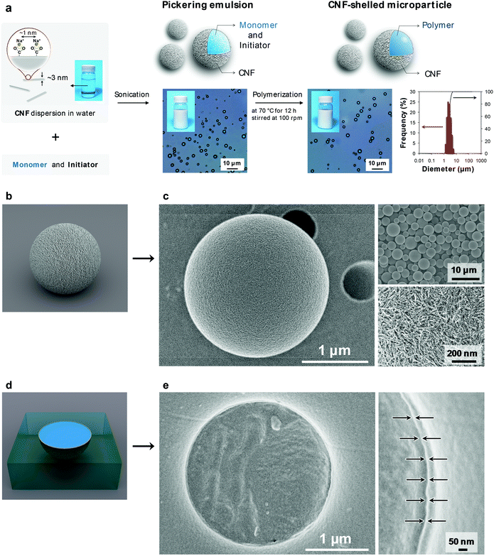
Here, we develop an approach to fabricating ultrathin and uniform CNF shell layers on polymer microparticles (Fig. 1a). The well-defined core/shell structure is achieved by an emulsion-templating approach, where the assembly is driven by a decrease in interfacial energy. In this study, CNFs with a width of ∼3 nm were prepared from wood cellulose by (2,2,6,6-tetramethylpiperidine-1-oxyl) TEMPO-mediated oxidation.17 Notably, the TEMPO-oxidized CNF had a high density of carboxy groups on its surface (∼1.7 groups per nm2),18 which efficiently improved the dispersibility. We investigated the structure and mechanical properties of the CNF-shelled polymer microparticles, and characterized the pH-sensitive affinity of the ultrathin CNF-shell towards therapeutic and biomedical applications.
The ultrathin CNF shell was formed by a spontaneous assembly at the interface of the monomer-in-water Pickering emulsion (Fig. 1a center). The CNF-stabilized Pickering emulsion was prepared by sonicating a mixture of divinylbenzene (DVB) monomer and CNF dispersion in water. The adsorption behaviour of aromatic compounds onto cellulose crystal surfaces has been theoretically and experimentally well-studied. Adsorption takes place at both hydrophilic and hydrophobic crystal surfaces with adsorption energies of the same order of magnitude.19,20 Therefore, the CNFs favourably attach at the DVB/water interface, driven by an overall decrease in the interfacial energy of the system.21 The emulsion showed good stability for over a week and no coalescence was observed. The size of the droplets depended on the sonication time. The size decreased with sonication time and the median diameter reached a constant value of ∼3 μm, when sonicated for over 1 min (ESI Fig. S2†), which is similar to that of cellulose nanocrystal/styrene emulsions reported by Capron et al. (∼4 μm).22
The CNF-shelled composite microparticles were synthesized by successive polymerization. The microparticles maintained the size and morphology of the droplets of the original Pickering emulsion even after the polymerization process. The median diameter was 3.0 μm, as determined by dynamic light scattering analysis (Fig. 1a right). The ζ-potential of the microparticle surfaces was −46.7 ± 0.5 mV. These results demonstrate that the microparticles were covered with dense CNF shells. The CNF-shelled microparticles were individually dispersed in water owing to the osmotic pressure arising from the surface anionic charges.
Notably, the size and shape of the original droplets remained intact even after polymerization. Generally, Pickering emulsions show better structural stability than surfactant-stabilized emulsions, because solid particles exhibit better mechanical properties and orders of magnitude higher adsorption energies at oil/water interfaces. By comparison, when water-soluble carboxymethyl cellulose was used as an emulsifier instead of the CNF, the emulsions coalesced during the polymerization (ESI Fig. S3†). Therefore, the CNF provided sufficient mechanical robustness to the emulsions. Furthermore, we confirmed that the uniform size and high surface charges of the CNF in this study played an important role in the synthesis of well-dispersed and uniform composite microparticles (ESI Fig. S3 and Table S1†).
We used scanning electron microscopy (SEM) imaging to visualize the composite structure of the CNF-shelled microparticles (Fig. 1c). The thin shell layer of CNF homogeneously covered the polymer microparticle surfaces (Fig. 1c bottom right, and see ESI Fig. S4†). The inside of the microparticle was filled with polymer, and no voids were observed in the SEM images (Fig. 1e). The thickness of the CNF shell was ∼8 nm, calculated based on the weight content of CNFs determined by thermogravimetry-differential thermal analysis (ESI Fig. S5†).
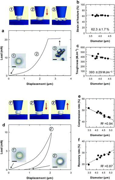
Mechanical properties of individual microparticles were evaluated by micro-compression testing (Fig. 2 and ESI Fig. S6†). The CNF-shelled microparticles exhibited strain at a fracture of 62.3 ± 1.7% and a fracture toughness of 393 ± 29 MJ m−3 (Fig. 2b and c). Importantly, there was little effect of the diameter on these values. These results indicate that each microparticle contained a homogeneous and void-free PDVB centre, as confirmed by SEM observations. Moreover, the mechanical properties of these materials were better than those of previously reported styrene–DVB microparticles,23,24 which we attribute to the denser cross-linked chemical structure formed by DVB. We also examined loading–unloading behaviour (Fig. 2d). Compression and recovery rates varied with the diameter (Fig. 2e and f), because the maximum load was fixed for all samples. The microparticles underwent plastic deformation with a maximum load of 9.8 mN and exhibited slight residual strain after unloading.
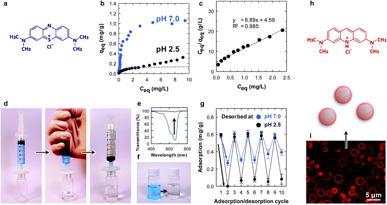
Interestingly, with the assistance of the surface carboxy groups of the CNF shell, the microparticle showed a pH-dependent equilibrium adsorption isotherm (Fig. 3b and c). At pH 7.0, the amount of adsorbed methylene blue (MB) at equilibrium (qeq) was higher at all equilibrium concentrations (Ceq) compared with that at pH 2.5. This is because the surface carboxy groups are available for ionic bonding with cationic MB, as is the case for clay minerals.25 Hence, it is likely that physisorption is the main adsorption mode at pH 2.5 rather than ionic bonding. The equilibrium data at pH 2.5 were fitted with the Langmuir model.26 At low Ceq, the equilibrium data agreed well with the Langmuir model (dotted line in Fig. 3b and c), which is a simple theoretical model for monolayer adsorption with a finite number of adsorption sites. We attribute the steady increase in qeq at higher values of Ceq at pH 2.5 for further assembly of MB molecules on the surfaces.27
The absorption behaviour was examined by a simple filtration procedure at pH 7.0 (Fig. 3d). The adsorption of MB onto the microparticles was rapid, and the concentration of MB decreased from 5 to 0.06 mg L−1 after filtration at a constant flow rate of ∼100 mL min−1 (Fig. 3e and f). Repeated adsorption/desorption testing was performed by changing the pH in the desorption process (Fig. 3g). After the adsorption of MB at pH 7.0 (cycle 1), the adsorbed MB was washed with an excess of pH 7.0 or 2.5 buffers (cycle 2). Notably, the microparticle showed pH-dependent desorption behaviour. Complete washing at pH 2.5 detached almost all the methylene molecules from the microparticle surfaces. The MB molecules attached through ionic bonding were not released at pH 7.0, as discussed above. MB removal behaviour has been reported so far.28,29 The adsorption/desorption process was repeatable for at least 10 cycles (Fig. 3g), demonstrating that the core/shell structure is physically stable and the CNFs did not peel from the surfaces during the process. Although the chemical structure of the CNFs on the surfaces was not able to be investigated due to the small amount, the adsorption behaviour was repeatable. This indicates that the CNFs were intact even after the process. The reusability combined with the tough and filterable properties of the microparticles make CNFs have potential applications as column packing materials.
The adsorption behaviour was visualized by confocal laser scanning microscopy, using acridine orange as a fluorescent dye (Fig. 3i). The dye was selectively adsorbed on the surfaces of the microparticles. Notably, the fluorescence of the CNF layers appeared to be thicker than that determined by SEM because the fluorescence image resolution is limited to ∼200 nm at a scan depth of ∼0.7 μm along the z axis.
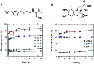
We examined the pH-sensitive drug release properties of the CNF shell under various pH conditions at 37 °C, using ranitidine and mitomycin C as model drugs (Fig. 4). Ranitidine and mitomycin C are an effective gastric secretory inhibitor and antitumor chemotherapeutic drug, respectively, and pH-responsive release is needed towards targeted delivery.30–32 As expected, the microparticles showed preferential drug release under acidic pH conditions, where the drug release was triggered by the dissociation of ionic bonding between anionic CNF and cationic drugs. In acidic solutions of pH of 1 and 2.5 (Fig. 4a and b, respectively), more than 70% of the drug was released within 10 min, which is approximately 4 times as high as the release at pH 7.
The release behaviours by the CNF shells were faster and more pH-selective than those of spray-dried CNF microparticles33 or CNF-reinforced alginate microspheres,34 likely because of the good dispersibility and well-defined structure of our microparticles. Generally, CNF gels show slow and sustained drug release properties over a period of several days35,36 or months,33,37 because the dense CNF network structure decreases the diffusivity of drug molecules. Although the CNF-shells in this work did not show the slow and long-lasting release properties, this material showed unique pH-triggered release properties and good dispersibility with small sizes. The characteristics of the ultrathin CNF shells are potentially useful for pH-responsive oral and tumour targeted31,38 drug delivery mediated by nano-/micro-carrier particles.
Conclusions
We prepared the ultrathin CNF shells on microcarrier surfaces, via spontaneous CNF assembly at monomer/water interfaces of the emulsion, followed by a polymerization process. The CNF-shelled microparticles exhibited good dispersibility, high toughness, and narrow size distributions, owing to the unique chemical and physical properties of the CNF. The ultrathin CNF shell could be effectively loaded with drug molecules, demonstrating its potential as a pH-sensitive carrier material in adsorption/desorption experiments. Furthermore, the CNF-shelled microparticles could be functionalized by surface modification or encapsulation with other nanomaterials. These unique carrier properties with a versatile range of behaviours show great potential for future advances in medical and pharmaceutical fields.Conflicts of interest
There are no conflicts to declare.Acknowledgements
This research was supported by Grants-in-Aid for Scientific Research Grant number JP17K15298 (to S. F.) from the Japan Society for the Promotion of Science (JSPS), and JST-Mirai R&D Program Grant number JPMJMI17ED (to S. F. and T. S.) from the Japan Science and Technology Agency (JST). We acknowledge Miyuki Komura of Olympus Co. Ltd., Japan, for arranging the confocal laser scanning microscopy observation.References
- A. N. Shipway, E. Katz and I. Willner, ChemPhysChem, 2000, 1, 18 CrossRef CAS.
- S. Kinge, M. Crego-Calama and D. N. Reinhoudt, ChemPhysChem, 2008, 9, 20 CrossRef CAS.
- Y. J. Min, M. Akbulut, K. Kristiansen, Y. Golan and J. Israelachvili, Nat. Mater., 2008, 7, 527 CrossRef CAS.
- A. Boker, J. He, T. Emrick and T. P. Russell, Soft Matter, 2007, 3, 1231 RSC.
- S. U. Pickering, J. Chem. Soc., 1907, 91, 2001 RSC.
- W. Ramsden, Proc. R. Soc. London, 1903, 72, 156 CAS.
- M. P. Zhu, Y. Muhammad, P. Hu, B. F. Wang, Y. Wu, X. D. Sun, Z. F. Tong and Z. X. Zhao, Appl. Catal., B, 2018, 232, 182 CrossRef CAS.
- F. Q. Tang, L. L. Li and D. Chen, Adv. Mater., 2012, 24, 1504 CrossRef CAS.
- Z. W. Niu, J. B. He, T. P. Russell and Q. A. Wang, Angew. Chem., Int. Ed., 2010, 49, 10052 CrossRef CAS.
- H. Ma, M. X. Luo, S. Sanyal, K. Rege and L. L. Dai, Materials, 2010, 3, 1186 CrossRef CAS.
- J. Sugiyama, J. Persson and H. Chanzy, Macromolecules, 1991, 24, 2461 CrossRef CAS.
- Y. Nishiyama, P. Langan and H. Chanzy, J. Am. Chem. Soc., 2002, 124, 9074 CrossRef CAS.
- Y. Nishiyama, J. Sugiyama, H. Chanzy and P. Langan, J. Am. Chem. Soc., 2003, 125, 14300 CrossRef CAS PubMed.
- N. Lin and A. Dufresne, Eur. Polym. J., 2014, 59, 302 CrossRef CAS.
- M. Jorfi and E. J. Foster, J. Appl. Polym. Sci., 2015, 132, 41719 CrossRef.
- M. M. Abeer, M. C. I. Mohd Amin and C. Martin, J. Pharm. Pharmacol., 2014, 66, 1047 CAS.
- A. Isogai, T. Saito and H. Fukuzumi, Nanoscale, 2011, 3, 71 RSC.
- Y. Okita, T. Saito and A. Isogai, Biomacromolecules, 2010, 11, 1696 CrossRef CAS PubMed.
- D. D. Perez, R. Ruggiero, L. C. Morais, A. E. H. Machado and K. Mazeau, Langmuir, 2004, 20, 3151 CrossRef.
- L. M. Ilharco, A. R. Garcia, J. L. daSilva and L. F. V. Ferreira, Langmuir, 1997, 13, 4126 CrossRef CAS.
- B. P. Binks and J. H. Clint, Langmuir, 2002, 18, 1270 CrossRef CAS.
- I. Kalashnikova, H. Bizot, B. Cathala and I. Capron, Langmuir, 2011, 27, 7471 CrossRef CAS.
- T. Tanaka, T. Suzuki, Y. Saka, P. B. Zetterlund and M. Okubo, Polymer, 2007, 48, 3836 CrossRef CAS.
- D. O. Kim and J. H. Jin, J. Appl. Polym. Sci., 2007, 104, 2350 CrossRef CAS.
- M. Rafatullah, O. Sulaiman, R. Hashim and A. Ahmad, J. Hazard. Mater., 2010, 177, 70 CrossRef CAS.
- I. Langmuir, J. Am. Chem. Soc., 1918, 40, 1361 CrossRef CAS.
- C. H. Giles, T. H. Macewan, S. N. Nakhwa and D. Smith, J. Chem. Soc., 1960, 3973 RSC.
- H. Liu, D. Q. Yu, T. B. Sun, H. Y. Du, W. T. Jiang, Y. Muhammad and L. Huang, Appl. Surf. Sci., 2019, 473, 855 CrossRef CAS.
- P. Hu, Z. X. Zhao, X. D. Sun, Y. Muhammad, J. Li, S. B. Chen, C. J. Pang, T. T. Liao and Z. X. Zhao, Chem. Eng. J., 2019, 356, 329 CrossRef CAS.
- M. Kanamala, W. R. Wilson, M. M. Yang, B. D. Palmer and Z. M. Wu, Biomaterials, 2016, 85, 152 CrossRef CAS.
- S. Ganta, H. Devalapally, A. Shahiwala and M. Amiji, J. Controlled Release, 2008, 126, 187 CrossRef CAS.
- J. Salonen, L. Laitinen, A. M. Kaukonen, J. Tuura, M. Bjorkqvist, T. Heikkila, K. Vaha-Heikkila, J. Hirvonen and V. P. Lehto, J. Controlled Release, 2005, 108, 362 CrossRef CAS.
- R. Kolakovic, T. Laaksonen, L. Peltonen, A. Laukkanen and J. Hirvonen, Int. J. Pharm., 2012, 430, 47 CrossRef CAS PubMed.
- N. Lin, J. Huang, P. R. Chang, L. D. Feng and J. H. Yu, Colloids Surf., B, 2011, 85, 270 CrossRef CAS.
- H. Paukkonen, M. Kunnari, P. Lauren, T. Hakkarainen, V. V. Auvinen, T. Oksanen, R. Koivuniemi, M. Yliperttula and T. Laaksonen, Int. J. Pharm., 2017, 532, 269 CrossRef CAS PubMed.
- Y. J. Dong, H. Paukkonen, W. W. Fang, E. Kontturi, T. Laaksonen and P. Laaksonen, Int. J. Pharm., 2018, 548, 113 CrossRef CAS PubMed.
- R. Kolakovic, L. Peltonen, A. Laukkanen, J. Hirvonen and T. Laaksonen, Eur. J. Pharm. Biopharm., 2012, 82, 308 CrossRef CAS.
- E. S. Lee, Z. G. Gao and Y. H. Bae, J. Controlled Release, 2008, 132, 164 CrossRef CAS PubMed.
Footnote |
| † Electronic supplementary information (ESI) available: Experimental methods, Fig. S1–S3, and Table S1. See DOI: 10.1039/c9nr02612f |
| This journal is © The Royal Society of Chemistry 2019 |


![[thin space (1/6-em)]](https://www.rsc.org/images/entities/char_2009.gif) :
:

