
 Open Access Article
 This Open Access Article is licensed under a Creative Commons Attribution-Non Commercial 3.0 Unported Licence
A novel phase function describing light scattering of layers containing colloidal nanospheres†
Junxin
Wang
a,
Changgang
Xu
ab,
Annica M.
Nilsson
a,
Daniel L. A.
Fernandes
a and
Gunnar A.
Niklasson
 *a
*a
aDepartment of Engineering Sciences, The Ångström Laboratory, Uppsala University, PO Box 534, SE-75121 Uppsala, Sweden. E-mail: Gunnar.Niklasson@angstrom.uu.se
bSchool of Materials Science and Engineering, Xi'an University of Science and Technology, Xi'an 710054, China
First published on 25th March 2019
Abstract
Light scattering from small particles exhibit unique angular scattering distributions, which are strongly dependent on the radius to wavelength ratio as well as the refractive index contrast between the particles and the surrounding medium. As the concentration of the particles increases, multiple scattering becomes important. This complicates the description of the angular scattering patterns, and in many cases one has to resort to empirical phase functions. We have measured the angle dependence of light scattering from a polymer layer containing sub-micron metallic and dielectric particles. The samples exhibited strongly forward and backward peaked scattering patterns, which were fitted to a number of empirical approximative phase functions. We found that a novel two-term Reynolds–McCormick (TTRM) phase function gave the best fit to the experimental data in all cases. The feasibility of the TTRM approach was further validated by good agreement with numerical simulations of Mie single scattering phase functions at various wavelengths and sizes, ranging from the Rayleigh scattering regime to the geometrical optics regime. Hence, the widely adaptable TTRM approach is able to describe angular scattering distributions of different kinds of nanospheres and nanocomposites, both in the single scattering and multiple scattering regimes.
Introduction
Light scattering from a material can be due to its surface or its volume, or to a combination of both.1,2 The detection of surface roughness by light scattering has many practical applications in industry, i.e., mapping of surface defects, scratches, surface contaminants, and particulates on silicon wafers and computer hard disks.1 The Facet Scattering Model is used for the characterization of large scale roughness, where the radius of curvature of the surface is much larger than the wavelength of light.3 For slightly rough surfaces, a first-order perturbation approximation, the so called Rayleigh–Rice equation4,5 has been adopted. The roughness parameters have been explored for thin-film coatings6 as well as for surfaces of small particles.7,8 Turning to volume scattering, the optical properties of pigments in a paint layer were first quantitatively studied by Kubelka and Munk at 1931,9 by analyzing the backscattering and absorption coefficients of the paint layer. Volume scattering distributions are important for a number of applied fields, ranging from marine scattering,10 underwater wireless optical communication systems,11 ice crystals,12 to tissues,13 human dermis,14etc.The scattering phase function15 characterizes the scattered intensity distribution as a function of scattering angle, and is a crucial parameter for understanding the optical characteristics of the materials in the framework of radiative transfer calculations.16 However, the scattering phase function for a plane-parallel structure containing scattering particles has not been studied sufficiently. In this work, we propose a measurement methodology to obtain the phase function of a light scattering layer in order to fit the angular dependence to empirical relations. We consider a layer containing functional light scattering nanoparticles, i.e. metallic Au, dielectric Fe3O4, and TiO2 nanospheres. These nanomaterials have found extensive applications in optics, magnetism, catalysis, sensing, etc. Au is a metallic plasmonic material. In nanoparticles, the free electron gas can be excited by incident light to collective resonances, manifestied as strongly localized surface plasmon modes.17 Au particles are used in applications like surface enhanced Raman spectroscopy, plasmonic sensing, photo-thermal and plasmon-assisted photochemical reactions.18 Magnetic Fe3O4 particles have been used in biosensors, exploiting optical variations under an applied magnetic field.19 TiO2 is a widely used pigment and sun-screen additive, which also has been employed as a scattering layer in dye-sensitized solar cells so that the path length of light is increased to facilitate a better absorption due to adsorbed dye molecules.15,20
The scattering distribution of a single isolated nanoparticle can be obtained by Mie theory using the scattering matrix21 approach. However, it is only valid for single scattering and the shape of the particles must be spherical and have a smooth surface. In reality, light scattering particles have irregular shapes with rough surfaces, for example marine scatterers and scatterers in tissue and blood. High pigment concentrations as well as particle aggregation are also common and in these cases multiple scattering effects will modify the phase function. Advanced methods like Monte Carlo modeling22,23 and Finite-difference time-domain (FDTD)24 require complex calculations. Several empirical phase function approximations have been developed in order to assess their feasibility for describing the single and multiple scattering scenarios. One of the most widely used analytic phase functions is the one-term Henyey–Greenstein (HG) phase function, which was first used in astrophysics.25 However, a major deficiency of HG is that it fails to describe the glory,26 for example caused by the backscattering of sunlight from small droplets of water, which is predicted by Mie theory.27 The two-term Henyey–Greenstein (TTHG) function, provides a better approximation for the backscattering peak that exists for many realistic particle distributions, for example marine ones.8 Cornette and Shanks,28 defined a single parameter phase function, which converges to the Rayleigh phase function for small particles and to the Henyey–Greenstein phase function for larger ones. Another alternative phase function was suggested by Reynolds and McCormick,29 and was found to fit well to data from several biological specimens. It works especially well for highly anisotropic scattering patterns. Forand and Fournier,30 proposed a phase function considering a particle size distribution of marine particulates, leading to an inverse power law behavior of scattering as a function of scattering angle.
The samples considered in the present work were considerably simpler and consisted of almost spherical nanoparticles dispersed in a layer. Our purpose was to find a facile approach to determine the effects of multiple scattering and aggregation on the phase function. By measuring the angular dependence of light scattering we could obtain a good empirical description of the multiple scattering phase function inside the layer. The experimental phase functions were compared to various empirical phase functions as well as revisions of them.
Results and discussion
Angle resolved light scattering
The synthesized Au, Fe3O4 and TiO2 nanospheres were prepared by a wet chemistry approach and had diameters of 203 ± 13 nm, 207 ± 48 nm, and 216 ± 34 nm (see Experimental, Fig. S1†). The nanospheres were dispersed in water followed by adding 80% PVP (compared to the weight of water). The volume fraction of the three types of nanoparticles (in water + 80 wt% PVP) was 0.066%. The viscous solutions containing the particles were encapsulated between two glass slides with gaps around 80 μm.We measured scattering intensity distributions from the samples by using a He–Ne laser with a wavelength of 633 nm. A three dimensional goniometer was used to record the scattered light intensity in the forward and backward half hemispheres (Fig. S2,† Experimental). The scattering intensity is presented as angle resolved scattering (ARS),3 which is defined as
 | (1) |
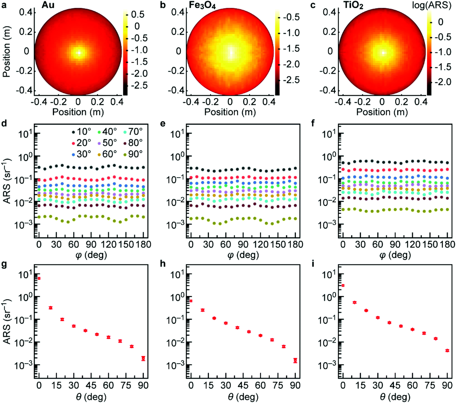 | ||
| Fig. 1 (a–c) Top view of the forward angle resolved scattering (ARS) against position for three nanoparticle scattering layers (in logarithmic scale). (d–f) Forward ARS as a function of azimuth angle taken at different polar angles from 0° to 90° at an interval of 10°. (g–i) Forward ARS plotted as a function of the polar angle. The wavelength of the incident light was 633 nm. | ||
We then plotted measured scattering data as a function of polar angle (θ) and azimuth angle (φ) (see Experimental). Fig. 1d–f shows ARS of forward scattering at various polar angles as a function of azimuth angle in logarithmic scale. Fig. 1d–f shows that scattering is mainly dependent on the polar angle and rather insensitive to the azimuth angle. The speckle-like pattern in Fig. 1a–c is probably caused by an inhomogeneous particle distribution. Fig. S3† shows corresponding backward scattering data as a function of polar/azimuth angle. Since the backward scattering is lower than the forward one, higher measurement fluctuations may occur. The data show clear evidence of negligible dependence on azimuth angle, indicating that scattering is mainly dependent on polar angle. Fig. 1g–i gives the ARS of forward scattering as a function of the polar angle.
Our in-house 3D goniometer works at single wavelength at 633 nm, and in order to characterize spectrally dependent properties of the samples, we use an angle resolved spectrometer to record the dependence on polar angle of the scattering profile at various wavelengths from 350 nm to 1000 nm. Fig. 2a and b show the forward and backward scattering pattern of a Fe3O4-PVP layer at a wavelength of 500 nm. The zoomed-in ARS in the insets of Fig. 2a and b show that collimated light is mainly detected at angles lower than 2° (shaded area). Within this interval, most of the signal comes from incident light which is not absorbed or scattered by the particles, but a minor portion results from light scattered by the nanoparticles at low angles. The latter one (the diffuse part) can be estimated by extrapolation from the intensity at angles larger than 2° (inset in Fig. 2a and b, open circles), and is 2 to 3 orders of magnitude lower than the collimated incident light. The full angle resolved diffuse scattering of Fe3O4 is shown in Fig. 2c. The corresponding plots for Fe3O4, Au and TiO2 at three different wavelengths are shown in Fig. S4.† In order to obtain the light intensity inside the scattering layer, outer and inner angles and intensities should be correlated by Snell's law and Fresnel's equations. Firstly, we use Snell's law to obtain the angle of propagation of light inside the layer (θi) from the outer scattering angle (θo) by taking account of the refractive index difference of the host (glass/(water + PVP)/glass), ni, to that of the air, no.
 | (2) |
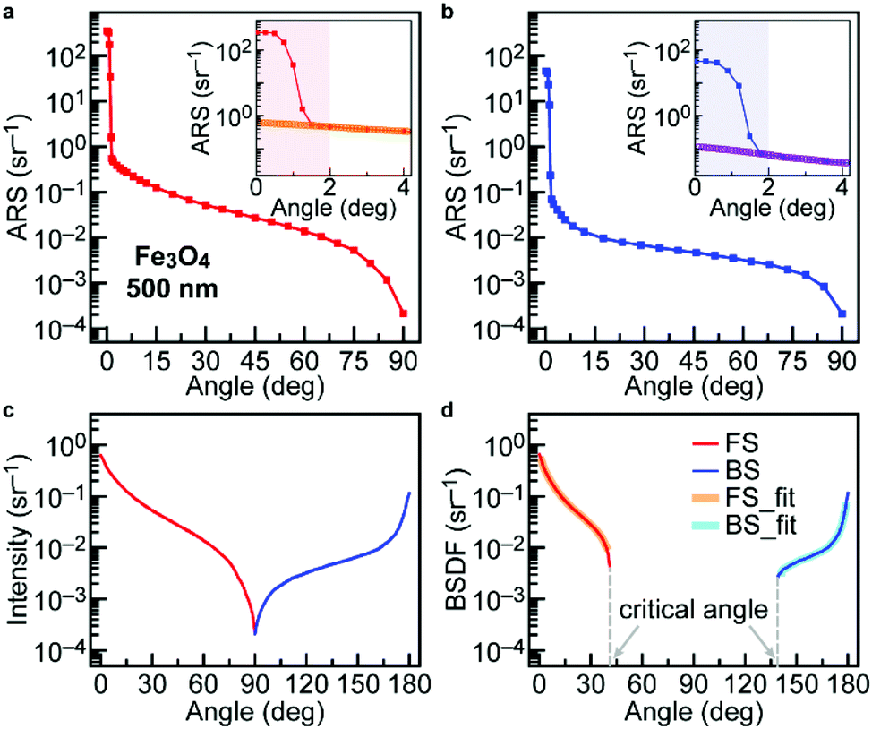 | ||
| Fig. 2 (a) Forward and (b) backward ARS intensity measured by an angle resolved spectrometer on a Fe3O4 nanosphere sample at a wavelength of 500 nm as a function of scattering angle from the normal/specular direction. The inset shows the ARS at small scattering angles. (c) Forward and backward intensity of diffuse scattering measured on the Fe3O4 sample at 500 nm as a function of polar angle. (d) Rescaled BSDF, converting the measured intensity from (c) into the scattering distribution inside the sample, by eqn (2) and (3). The broad orange/cyan curves denote the angular ranges used for fitting. | ||
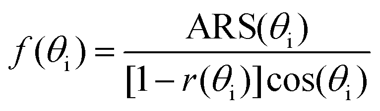
Then the measured ARS is used to obtain the bidirectional scattering distribution function (BSDF, denoted f).3 The difference between ARS and BSDF is the cosine correction factor, cos(θ), to correct for the surface area at the viewing angle. The phase function describes the angular distribution of the scattered radiation inside the material and is analogous to BSDF.1,31 We also correct for the Fresnel reflectance from glass to air and obtain,
 | (3) |
The obtained BSDF of a Fe3O4 layer is shown in Fig. 2d, combining information from measurements of forward and backward scattering. It is seen that angular information of the BSDF is missing due to total internal reflection at angles larger than the critical angle. In order to bridge this gap in angles, fitting to a proper model of the phase function is required. However, it is evident that the BSDF must be very low at angles between 40° and 140° and values in this interval will not affect total scattering much. We choose to fit the BSDF to empirical phase functions in the range is from 1.3°–39° for the forward region and 141°–178.7° for the backward region (thick lines in Fig. 2d), thus avoiding the region where collimated transmittance and reflectance dominate. In addition, the drop in intensity close to the critical angles may be due to the detector sensitivity (see Experimental).
Comparison to empirical phase functions
We first review a number of empirical phase functions that have been proposed previously and then use them to fit our experimental data. Reynold and McCormick (RM) proposed a phase function approximation which described highly anisotropic angular scattering distributions and has the following analytic form:29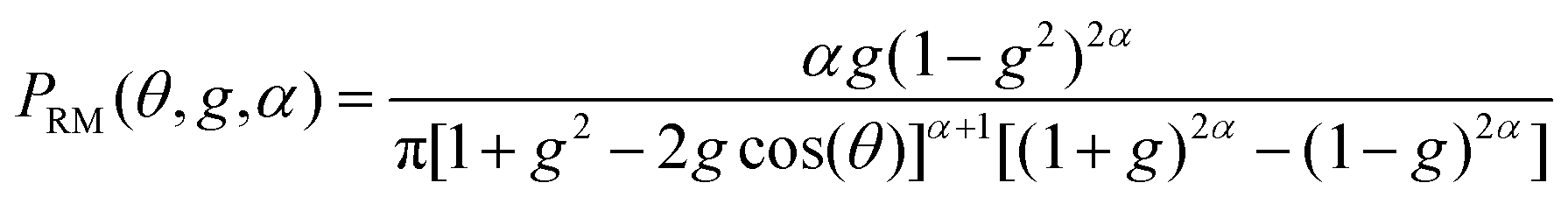 | (4) |
When the fitting parameter α equals 0.5, it reduces to the so-called Henyey–Greenstein (HG) phase function:25
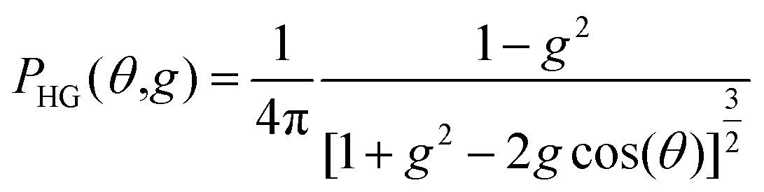 | (5) |
 | (6) |
The advantage of the RM phase function as compared to the HG phase function is that it better reproduces strongly anisotropic scattering angular distributions. However, both of them can fit only forward peaked or backward peaked scattering distributions, and fail for distributions that are both forward and backward peaked. In order to overcome this deficiency and better represent the backscattering peak, a two-term modified HG phase function has been proposed (TTHG),10
| PTTHG(θ,γ,g1,g2) = γPHG(θ,g1) + (1 − γ)PHG(θ,g2) | (7) |
This function has two parts with two different asymmetry factors, where g1 is positive and g2 is negative, in order to treat the forward and backward peaks in the phase function. The parameter γ gives the forward scattering portion while (1 − γ) is the backward scattering portion. Guided by the TTHG, we have revised the RM function in a similar way, and we denote this function as the two-term Reynolds–McCormick or TTRM phase function:
| PTTRM(θ,g1,g2,α1,α2,γ) = γPRM(θ,g1,α1) + (1 − γ)PRM(θ,g2,α2) | (8) |
Compared to TTHG, TTRM has two more fitting parameters, namely α1 and α2. Besides TTHG and TTRM, we also examined the Cornette Shanks (CS) phase function:28
 | (9) |
The CS phase function, has only one variable, that is the asymmetry factor g. When g is close to 0 it converges to the Rayleigh phase function and when g is close to 1 it approaches the HG phase function, therefore, it provides a realistic description of the scattering by small particles. The deficiency of the CS phase function is that it fails to reproduce the sharp forward/backward scattering peak. The Forand–Fournier phase function (FF) was first derived for scatterers in oceanic water, and considers a power law for the particle size distribution and mean index of refraction of the scattering particles:30
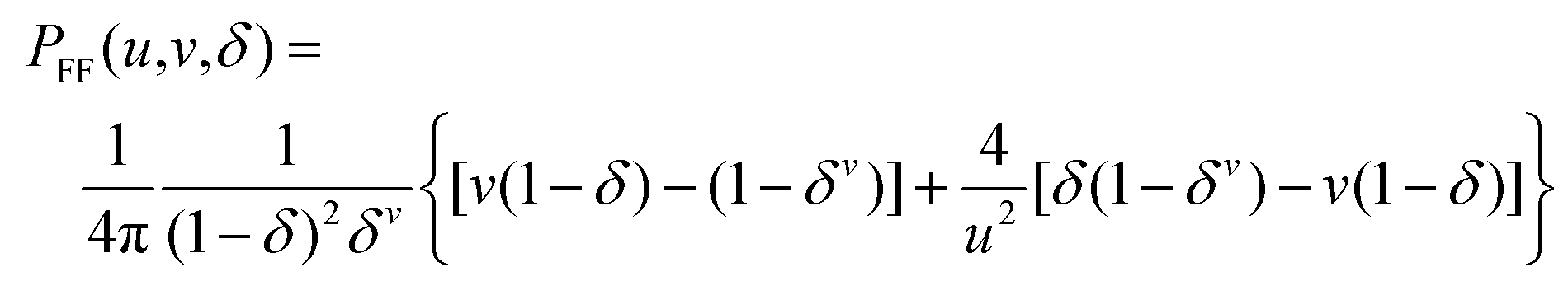 | (10) |
![[thin space (1/6-em)]](https://www.rsc.org/images/entities/char_2009.gif) sin(θ/2). Similar to the cases of TTHG and TTRM, we extend it to a two-term form (TTFF) for fitting the forward and backward peaked case. The above-mentioned phase functions emerge from physical arguments, but we also propose a mathematical analytic form for fitting forward and backward peaked scattering distributions based on a parabolic curve. This approximation is denoted as PARA:
sin(θ/2). Similar to the cases of TTHG and TTRM, we extend it to a two-term form (TTFF) for fitting the forward and backward peaked case. The above-mentioned phase functions emerge from physical arguments, but we also propose a mathematical analytic form for fitting forward and backward peaked scattering distributions based on a parabolic curve. This approximation is denoted as PARA:| PPARA(θ,a,b,c) = exp[a + b(θ − c)2] | (11) |
Omitting the less suitable one-term functions, we now have 5 different analytic approximations to the phase function, namely TTRM, TTHG, TTFF, CS and PARA, which were fitted to the experimental data. The quality of fit was described by the mean square logarithmic error (MSLE) criterion, which was used to find the difference of the fitted curve to the BSDF from the experiment:
 | (12) |
The reason to take logarithmic error is because there are orders of magnitude differences within the same scattering profiles, otherwise the fitting will be dominated by the largest values. The fitting curves (green) of the TTRM, TTHG, PARA, TTFF and CS approximations for a Fe3O4 sample are plotted in Fig. 3a–e, and in addition Fig. S5† gives analogous data for Au and TiO2 samples, all at 500 nm. Among them, TTRM exhibits the lowest MSLE for all the samples at all wavelengths, followed by the TTHG and PARA approximations (Fig. 3f–h). CS shows the worst fit among these five methods, probably because it only contains one fitting parameter, g, and is more suitable for fitting Rayleigh like scattering phase functions. The one-term functions HG, RM and FF fail to reproduce the backscattering peaks (Fig. S6†).
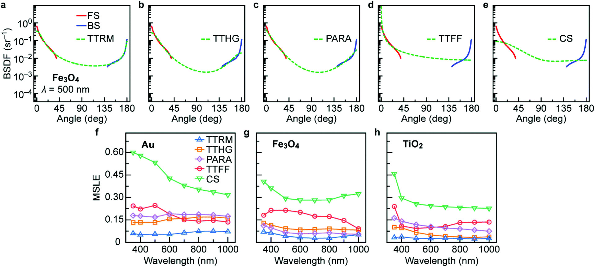 | ||
| Fig. 3 Fitting of the forward and backward scattering distributions for a Fe3O4 nanosphere sample at a wavelength of 500 nm by the (a) TTRM, (b) TTHG, (c) PARA, (d) TTFF, and (e) CS empirical phase functions. (f–g) Mean square logarithmic error (MSLE) of the above five methods at wavelengths from 350 nm to 1000 nm, for Au (f), Fe3O4 (g) and TiO2 (h) samples. | ||
It is seen that TTRM and TTHG phase functions have the lowest MSLE among these approximations. The largest discrepancies frequently occur close to the critical angles where the experimental data in several cases exhibit a sharp drop. However, at these points experimental uncertainties may be significant and we cannot be certain that these features are physical. In addition, the TTHG function has problems to fit data close to the forward and backward directions. The comparison of TTRM and TTHG function to the experimental BSDF of Fe3O4 from 350 to 1000 nm is shown in Fig. 4. In addition, Fig. S7 and S8† show analogous data for the Au and TiO2 samples.
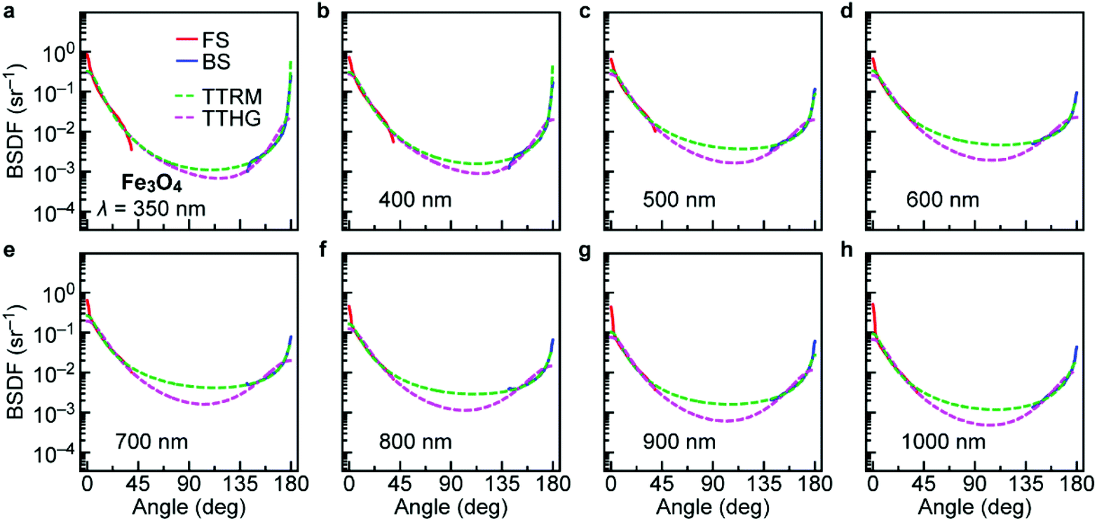 | ||
| Fig. 4 Fitting of the forward and backward scattering distributions for a Fe3O4 sample at wavelengths from 350 nm to 1000 nm (a–h) by use of the TTHG and TTRM phase function approximations. | ||
Compared to TTHG, TTRM better follows the trend of both forward and backward scattering branches, especially close to 0° and 180°, which can be to a large extent attributed to the introduction of scattering anisotropy in both directions by the fitting parameters α1 and α2.
We now examine the fitting parameters obtained from these samples. Turning to TTRM, the forward and backward asymmetry factors g1 and g2, together with the two new free parameters α1 and α2 are plotted in Fig. 5a–c. The asymmetry factors are close to 1 and −1, respectively, signifying a strongly forward and backward peaked scattering pattern. The fitted forward portion, γ, is significantly above 0.5, indicating that forward scattering is dominant (Fig. 5d–f). The asymmetry factors and forward scattering fraction, obtained from fits to the TTHG functions, show qualitatively similar behaviours (Fig. S9†). However, we found that a higher averaged asymmetry factor leads to a lower backscatter fraction in the TTHG fits (Fig. S9d, h, l†). Because of the introduction of the parameters α1 and α2 in the TTRM function, the asymmetry factor is not the only factor determining the backscattering and hence there is no systematic relation between the backscatter fraction and the average asymmetry factor in this case (Fig. S10†).
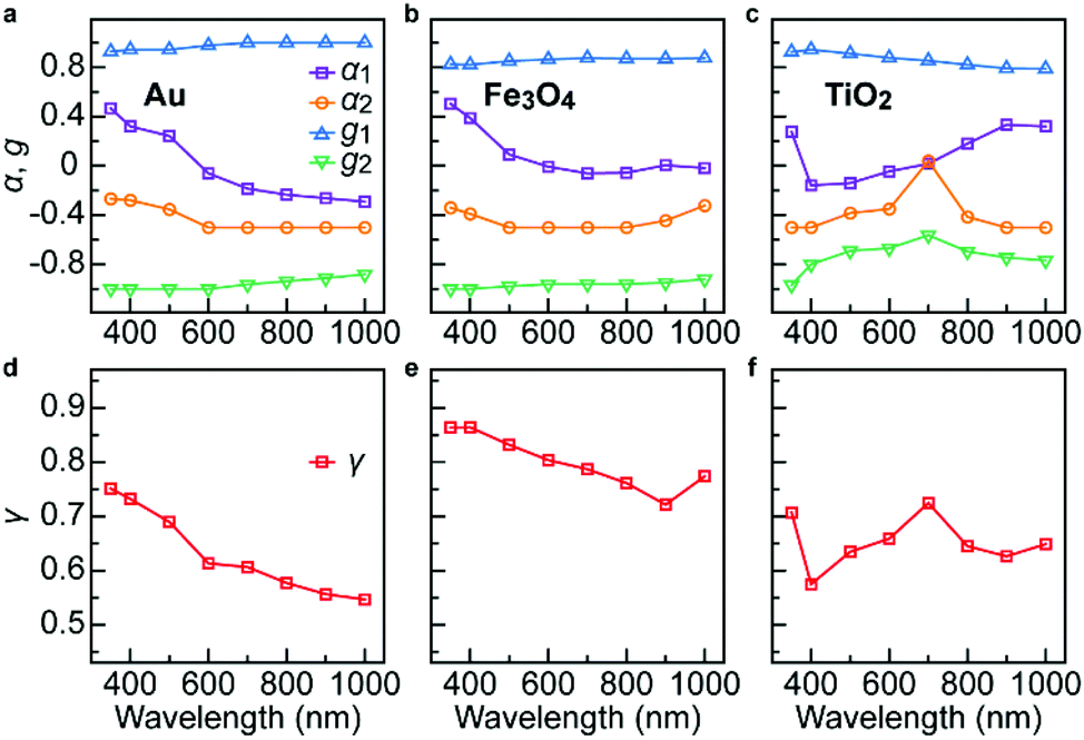 | ||
| Fig. 5 Parameters obtained from fits to the TTRM function for Au, Fe3O4 and TiO2 nanoparticle samples as a function of wavelength: α1, α2, g1, g2 for (a) Au, (b) Fe3O4 and (c) TiO2 samples and the forward portion γ for (d) Au, (e) Fe3O4 and (f) TiO2 samples. | ||
TTRM fit to Rayleigh and Mie phase functions
It was shown above that the TTRM phase function can fit our experimental scattering distributions with good accuracy. The experimental data is influenced by multiple scattering, most probably due to aggregation of particles in the samples (Fig. S11†). In order to verify the feasibility of the TTRM function in a broader context, we now compare TTRM with the Mie scattering phase function, that describes scattering from a single spherical particle or the single scattering regime of a nanoparticle composite. Mie theory15 was used to calculate the far-field scattering pattern around the particle. The Mie phase function considering the measured size distributions of the three types of particles, as obtained from SEM images (Fig. S1†), with average diameters about 200 nm are plotted and fitted by the TTRM expression as a function of wavelength from 400 nm to 1200 nm (Fig. 6). Results show that the TTRM function overlaps with the Mie phase functions in many cases, but slight discrepancies appear when there are oscillations in the Mie calculations owing to excitations of higher order eigenmodes, or normal modes.21 From the scattering phase function, one can notice that at shorter wavelengths, forward scattering is dominant while the backward portion increases with increasing wavelength.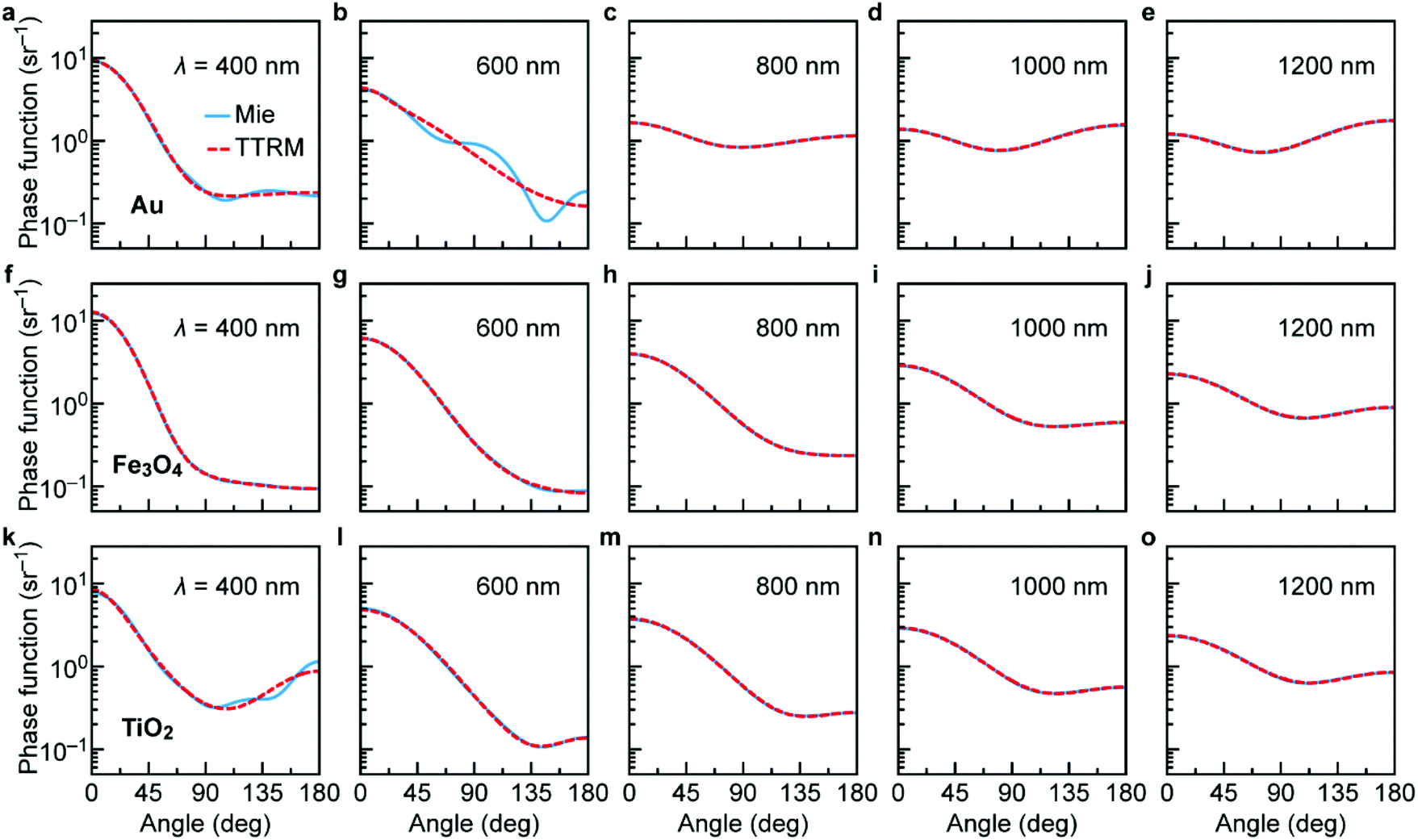 | ||
| Fig. 6 Comparison of TTRM (red) phase functions with Mie (blue) phase functions for Au (a–e), Fe3O4 (f–j) and TiO2 (k–o) particles at wavelengths of 400 nm, 600 nm, 800 nm, 1000 nm and 1200 nm. The Mie calculations were carried out using the experimental size distributions of nanoparticles with average diameters around 200 nm. | ||
We now explore phase functions from Mie theory for particles with diameters different from 200 nm. The size parameter, x = 2πa/λ, where a is the radius of the nanosphere and λ is the wavelength of incident light, is frequently used in the field of optical scattering to define different scattering domains. For x significantly less than one Rayleigh scattering predominates. For x > 20 one enters the geometric optics regime and the intermediate regime is often called the Mie scattering regime. The Rayleigh phase function describes the angular scattering distribution of unpolarized light by small particles:21
| PRayleigh(θ) ∼ (1 + cos2(θ)) | (13) |
The Rayleigh scattering function is symmetric, with maxima at 0° and 180° while minima appear at 90° and 270°. In the Mie region, the scattering pattern becomes more anisotropic and forward scattering dominates more as the particle size increases. We present Mie calculations for a wavelength of 600 nm, with diameters of single particles equal to 50, 150, 300, 500 and 1000 nm, corresponding to size parameters x equal to 0.26, 0.79, 1.57, 2.62 and 5.24 and fitted them by the TTRM function (Fig. 7). Multiple peaks appear when x is larger than one. The fitting in the Rayleigh region (first column), and Mie region when x is smaller than unity (second column), between the TTRM and Rayleigh/Mie phase functions is excellent. The TTRM function still follows the trend when x is larger than 1, although it does not describe the multiple peaks occurring due to higher order eigenmodes. However, in practical light scattering measurements, these peaks are usually smoothed due to size and shape distributions of the particles; in addition multiple scattering and the surface roughness of the particles may also contribute to this effect. Results for particles with diameters of 2000 nm (x = 10.5), 4000 nm (x = 21.0), 10000 nm (x = 52.4) are plotted in Fig. S12,† illustrating the fitting capability of the TTRM also in the geometric optics regime.
 | ||
| Fig. 7 Comparison of the TTRM (red) phase function with the Mie scattering model (blue) for Au (a–e), Fe3O4 (f–j) and TiO2 (k–o) particles with diameters of 50 nm, 150 nm, 300 nm, 500 nm and 1000 nm. The simulation was conducted at a wavelength of 600 nm. | ||
Discussion
We now discuss the physics associated with light scattering in the nanoparticle composites studied in this paper. We have found that the two-term Reynold–McCormick phase function can fit single scattering Mie calculations within a wide range of particle sizes. In the multiple scattering region a larger variety of scattering patterns can appear and the physical mechanisms are more complex.32 Previous approaches, like the HG and TTHG functions have particular problems with fitting strongly anisotropic scattering patterns in both forward and backward directions, such as those found experimentally here. It now remains to elucidate the physical reasons for these scattering patterns. Our samples had a low volume fraction and contained particles with diameters around 200 nm. The single scattering from such particles was shown to be strongly directed forward in most cases (Fig. 6), and this could explain the forward scattering peaks observed in Fig. 3 and 4. Furthermore, it is observed that the backscattering peak is about an order of magnitude lower that the forward one. An important contribution to the backscattering undoubtedly comes from unscattered or low-angle scattered light, that is reflected at the back interface of the sample and subsequently forward scattered by the particles on its return path to the front surface. Multiple scattering would make the scattering pattern more isotropic33 and hence the forward and backward scattering peaks would diminish. These effects are evidently not very strong in our case. However, dependent scattering from particle clusters due to particle aggregation in our samples (Fig. S11†) cannot be ruled out. Coherent backscattering from particle clusters would enhance the backscattering peak.34,35 In addition, aggregated particles can approximately be represented by equal volume spheres with larger sizes and this effect would also enhance the forward scattering peak.Conclusions
In this paper, we measured the angular resolved light scattering distribution of plasmonic and dielectric nanoparticle composites as a function of wavelength from 350 nm to 1000 nm. From the experimental data we could obtain an effective scattering phase function inside the composite layer. This function exhibits peaks in the forward and backward directions and the experimental data are restricted to angles closer to the surface normal than the critical angles of total internal reflection. The experimental results were compared to eight different empirical phase functions and we found that a two-term Reynolds–McCormick (TTRM) phase function provided the best fit to the experimental results. We further validated the TTRM approximation for the case of single scattering by comparing the TTRM function to calculations by Mie theory. We found that the TTRM is a good approximation for the Rayleigh and Mie scattering regimes, up to size parameters of 2 to 3, and can even be extended in an average sense to the geometric optics regime. In case of multiple scattering, the oscillations in the phase function will diminish and the TTRM function is expected to be valid in an even more extended range of size parameters. In particular we have shown that it gives an excellent description to the case of phase functions that are strongly peaked in both the forward and backward directions. Our results hence establish a useful approximation to the scattering phase function of metallic and dielectric nanoparticles and composites, which can be used for model calculations in a number of applications such as pigmented coatings, marine scatterers, biological materials, and particulate air contaminants.Experimental
Sample synthesis and characterization
The three types of nanoparticle samples were prepared using a bottom-up wet chemistry method, which allows for good control of the shape and size of nanostructures. Au nanospheres (NSs) were obtained by a seed-mediated growth together with mild oxidation, starting from small Au NSs, growing to nanopolyhedra, and reshaping to ∼200 nm diameter Au NSs by etching the edges.36 In a typical synthesis of Fe3O4 NSs, FeCl3·6H2O (0.1 g), polyvinylpyrrolidone (PVP, MW: 40000, 4 g), sodium acetate trihydrate (NaAc·3H2O, 0.3 g) and 1 mL of polyethylene glycol (PEG, MW: 300) were dissolved in 20 mL of ethylene glycol under stirring and ultrasonic treatment. The homogeneous yellow mixture was then transferred to a 50 mL Teflon-lined stainless-steel autoclave which was sealed and heated to 200 °C for 4 h. The Fe3O4 NSs were formed and collected by a magnet, washed with 50 mL distilled water, and collected by centrifugation at 1700 rpm for 20 min. The washing and centrifugation processes were repeated 5 times. The Fe3O4 NSs were eventually obtained after drying overnight at 80 °C. TiO2 NSs were synthesized using a similar procedure previously described by Han37 with minor modifications. Briefly, 200 μL of CaCl2 solution (0.05 M) was added to 50 mL methanol into a 100 mL one-necked flask and stirred for 10 min. Then 850 μL of titanium(IV) isopropoxide was added dropwise. The resulting solution was magnetically stirred for 24 h at room temperature. The synthesized TiO2 NSs were subsequently washed with 50 mL distilled water and collected by centrifugation at 1700 rpm for 20 min. The washing and centrifugation processes were repeated 5 times. The TiO2 NSs were obtained by calcination at 450 °C for 2 h with a ramp rate of 5 °C min−1.
The Au, Fe3O4 and TiO2 NSs were added to water at a concentration of 19.3 mg mL−1, 5 mg mL−1 and 4 mg mL−1, corresponding to 0.1% in volume fraction, equivalent to a particle concentration of 2.39 × 10¹¹ mL−1. Then PVP was added into the NS/water solution at a mass ratio of 0.8 (PVP/water). PVP has high viscosity, good binding capability with water, it dissolves at room temperature and is highly stable and nontoxic. The NS/water/PVP solution was vigorously shaken in a vortex mixer until the PVP powders dissolved completely. The viscous solution was deposited on a glass slide, subsequently another glass side with a spacer ∼80μm in thickness was added on top. The particle-PVP composite sample was sealed with glue and measurements took place after two weeks when the samples had stabilized. Significant particle aggregation can be found in the nanoparticle composites when studied under the microscope (Fig. S11†).
Scanning electron microscope images (Fig. S1†) were acquired by a Zeiss (LEO) 1530 FEG microscope at an acceleration voltage of 5 keV. Particle diameters and size distributions were determined by Adobe Illustrator software.
Optical characterization
The ‘in-plane’ angular and spectral resolved spectrometer consisted of a tungsten-halogen lamp, a monochromator, two gratings, an off-axis parabolic aluminum mirror with an off-axis distance of 80 mm and a focal length of 410 mm. The detector was a silicon diode with a spectral response region from 300 nm to 1100 nm and a port dimension of 6.4 × 6.4 mm2. The sample was centrally mounted and illuminated, and the silicon detector could be positioned at various angles from 0° to 180°. To increase the dynamic range of the measurement, we applied different neutral density filters (Thorlabs) for measurements at different wavelengths. These filters are designed for 633 nm. A 50% filter was used for 350 nm (transmittance of 0.16258), a 1% filter was used for 400 nm (transmittance: 0.00266), 500 nm (transmittance: 0.00653), 600 nm (transmittance: 0.00747), a 0.1% filter was used for 700 nm (transmittance: 0.00512), 800 nm (transmittance: 0.01159), 900 nm (transmittance: 0.01138), 1000 nm (transmittance: 0.01012). The incident light spot was much smaller than the port of the Si detector. The incident light intensity Pi was calculated using the measured intensity with the filter Ifilter, divided by the filter transmittance at the specific wavelength. The light spot spanned an angle within ±1°. The transmittance and reflectance were measured as a function of angle at a fixed wavelength. An angle of 10° of the sample normal to the incident light was used for reflectance measurements, to be able to measure the specular and near-specular reflected intensity, subsequently the data were shifted by Harvey's method.38 The measured radiant intensity was represented in the form of angle resolved scattering (ARS), by normalizing with the incident light intensity Pi and the solid angle Ω of the detector:3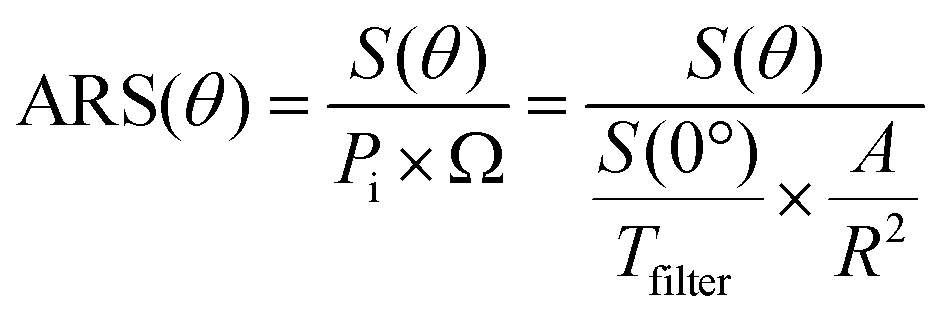 | (14) |
The ‘out-of-plane’ spatial scattering intensity distribution was measured using a home-built goniometer.39 The light source was a red He-Ne laser (wavelength λ = 633 nm). The position-controlled detector was mounted on a movable arm, thereby allowing the detector to move in a hemisphere. The radius of the semicircular arc was 45 cm. The sample was fixed at the center of the hemisphere traced by the movable arm, and was free to rotate around a horizontal axis, to vary the angle of incidence. The sample holder, the detector, and the arc were controlled by stepping motors. We illuminated a relatively small spot on the sample and measured the amount of light scattered into a known solid angle (under-illumination method).3 The detector was a silicon diode with a spectral response region from 300 nm to 1100 nm with port dimension 2.5 × 2.4 mm2. The incident light intensity was measured using a neutral density filter with a transmittance of 0.0004821 at 633 nm. In transmittance mode, the incident light was parallel to the normal of the sample surface. In the reflectance mode, the incident light was incident at 10° to the sample normal, the same as in the in-plane scattering measurement. The position of the sample to the incident light was fixed, and we measured a half hemisphere both in transmittance and reflectance regions and mirrored their intensity distributions to the other half hemisphere. The data analysis was similar to the in-plane spectrometer; the intensity was divided by the incident light intensity Pi and the solid angle Ω of the detector port. The arm moved from −90° to 90° while the detector moved in the range from −68° to 68° on the arm due to the geometry of the instrument. The measured data are presented as a function of real three dimensional position, (x, y, z). Then we convert the real position (x, y, z) into the polar (θ) and azimuth angles (φ) by,
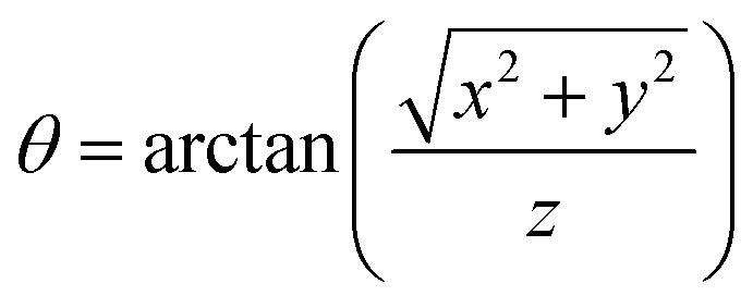 | (15) |
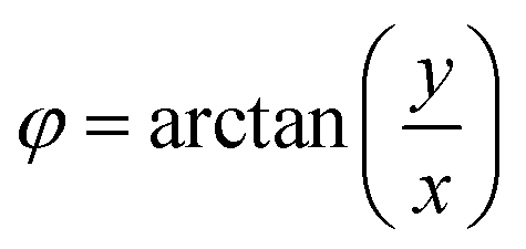 | (16) |
Mie theory modeling
The electrodynamic response of particles of spherical shape can be analytically and effectively solved with Mie theory.21 The scattering phase function for the three types of nanospheres was computed using the program MiePlot version 4.6.40 The calculations by Mie theory took into consideration the particle size distributions measured from SEM images (Fig. S1†). The refractive index database of Au,41 Fe3O442 and TiO243 were used as input for the optical properties of the nanospheres while the optical constants of the surrounding medium were taken from the calculated n, k obtained from Treg and Rspe of a glass/(water + PVP)/glass sample, using the method of McPhedran et al.44
Mie theory was used to calculate the far-field scattering pattern around the particle.15 In Mie theory,15 the scattering phase function F(θ, φ) defines the intensity of the scattered light in an arbitrary direction.
| F(θ, φ) = i2(θ)cos2(φ) + i1(θ)sin2(φ) | (17) |
Conflicts of interest
There are no conflicting interests to declare.Acknowledgements
This work was financially supported by the Swedish Research Council grant 2016-03713. We are grateful to Nanoseedz Reagent Co., Ltd (Hong Kong, China) for supplying the Au nanospheres.References
- J. C. Stover, Optical scattering: measurement and analysis, SPIE Optical Engineering Press, Bellingham, WA, USA, 1995 Search PubMed.
- A. K. Fung and H. J. Eom, IEEE Trans. Geosci. Remote Sens., 1982, GE-20, 528–536 Search PubMed.
- T. A. Germer, J. C. Zwinkels and B. K. Tsai, Spectrophotometry: Accurate measurement of optical properties of materials, Elsevier Science, Amsterdam, The Netherlands, 2014 Search PubMed.
- Lord Rayleigh, Proc. R. Soc. London, Ser. A, 1907, 79, 399–416 CrossRef.
- S. O. Rice, Commun. Pur. Appl. Math., 1951, 4, 351–378 CrossRef.
- S. Schröder, T. Herffurth, H. Blaschke and A. Duparré, Appl. Opt., 2011, 50, C164–C171 CrossRef PubMed.
- C. Liu, R. L. Panetta and P. Yang, J. Quant. Spectrosc. Radiat. Transfer, 2013, 129, 169–185 CrossRef CAS.
- C. Li, G. W. Kattawar and P. Yang, J. Quant. Spectrosc. Radiat. Transfer, 2004, 89, 123–131 CrossRef CAS.
- P. Kubelka and F. Munk, Z. Tech. Phys., 1931, 12, 593–601 Search PubMed.
- V. I. Haltrin, Appl. Opt., 2002, 41, 1022–1028 CrossRef PubMed.
- C. Gabriel, M.-A. Khalighi, S. Bourennane, P. Léon and V. Rigaud, J. Opt. Commun. Netw., 2013, 5, 1–12 CrossRef.
- A. J. Baran, V. N. Shcherbakov, B. A. Baker, J. F. Gayet and R. P. Lawson, Q. J. R. Meteorol. Soc., 2005, 131, 2609–2616 CrossRef.
- P. Thueler, I. Charvet, F. Bevilacqua, M. St. Ghislain, G. Ory, P. Marquet, P. Meda, B. Vermeulen and C. Depeursinge, J. Biomed. Opt., 2003, 8, 495–503 CrossRef PubMed.
- S. L. Jacques, C. A. Alter and S. A. Prahl, Lasers Life Sci., 1987, 4, 309–334 Search PubMed.
- H. C. van de Hulst, Light Scattering by Small Particles, Wiley, New York, 1957 Search PubMed.
- D. Toublanc, Appl. Opt., 1996, 35, 3270–3274 CrossRef CAS PubMed.
- U. Kreibig and M. Vollmer, Optical properties of metal clusters, Springer-Verlag, Berlin, 1995 Search PubMed.
- H. Chen, L. Shao, Q. Li and J. Wang, Chem. Soc. Rev., 2013, 42, 2679–2724 RSC.
- B. Tian, J. Ma, Z. Qiu, T. Zardán Gómez de la Torre, M. Donolato, M. F. Hansen, P. Svedlindh and M. Strömberg, ACS Nano, 2017, 11, 1798–1806 CrossRef CAS PubMed.
- F. Huang, D. Chen, X. L. Zhang, R. A. Caruso and Y.-B. Cheng, Adv. Funct. Mater., 2010, 20, 1301–1305 CrossRef CAS.
- C. Bohren and D. R. Huffman, Absorption and Scattering of Light by Small Particles, John Wiley & Sons, New York, 1998 Search PubMed.
- B. C. Wilson and G. Adam, Med. Phys., 1983, 10, 824–830 CrossRef CAS PubMed.
- Z. Liu, K. Wang, X. Luo and S. Liu, Opt. Express, 2010, 18, 9398–9412 CrossRef CAS PubMed.
- W. Sun, Q. Fu and Z. Chen, Appl. Opt., 1999, 38, 3141–3151 CrossRef CAS PubMed.
- L. C. Henyey and J. L. Greenstein, Astrophys. J., 1941, 93, 70–83 CrossRef.
- P. Laven, Appl. Opt., 2005, 44, 5675–5683 CrossRef PubMed.
- G. W. Kattawar, J. Quant. Spectrosc. Radiat. Transfer, 1975, 15, 839–849 CrossRef.
- W. M. Cornette and J. G. Shanks, Appl. Opt., 1992, 31, 3152–3160 CrossRef CAS PubMed.
- L. O. Reynolds and N. J. McCormick, J. Opt. Soc. Am., 1980, 70, 1206–1212 CrossRef.
- G. R. Fournier and J. L. Forand, Proc. SPIE, 1994, 2258, 194–201 CrossRef.
- I. Gkioulekas, B. Xiao, S. Zhao, E. H. Adelson, T. Zickler and K. Bala, ACM Trans. Graph., 2013, 32, 1–19 Search PubMed.
- H. C. van de Hulst, Multiple light scattering: tables, formulas, and applications, Academic, New York, 1980 Search PubMed.
- J. Piskozub and D. McKee, Opt. Express, 2011, 19, 4786–4794 CrossRef CAS PubMed.
- E. Akkermans, P. E. Wolf and R. Maynard, Phys. Rev. Lett., 1986, 56, 1471–1474 CrossRef CAS PubMed.
- L. Tsang and A. Ishimaru, J. Opt. Soc. Am. A, 1984, 1, 836–839 CrossRef.
- Q. Ruan, L. Shao, Y. Shu, J. Wang and H. Wu, Adv. Opt. Mater., 2014, 2, 65–73 CrossRef.
- C. Han, R. Luque and D. D. Dionysiou, Chem. Commun., 2012, 48, 1860–1862 RSC.
- J. E. Harvey, Proc. SPIE, 1990, 1165, 87–99 CrossRef.
- M. Rönnelid, M. Adsten, T. Lindström, P. Nostell and E. Wäckelgård, Appl. Opt., 2001, 40, 2148–2158 CrossRef.
- P. Laven, 2018, http://www.philiplaven.com/mieplot.htm.
- S. Babar and J. H. Weaver, Appl. Opt., 2015, 54, 477–481 CrossRef CAS.
- A. Schlegel, S. F. Alvarado and P. Wachter, J. Phys. C: Solid State Phys., 1979, 12, 1157–1164 CrossRef CAS.
- L. Miao, P. Jin, K. Kaneko, A. Terai, N. Nabatova-Gabain and S. Tanemura, Appl. Surf. Sci., 2003, 212–213, 255–263 CrossRef CAS.
- R. C. McPhedran, L. C. Botten, D. R. McKenzie and R. P. Netterfield, Appl. Opt., 1984, 23, 1197–1205 CrossRef CAS PubMed.
Footnote |
| † Electronic supplementary information (ESI) available. See DOI: 10.1039/c9nr01707k |
| This journal is © The Royal Society of Chemistry 2019 |