
 Open Access Article
 This Open Access Article is licensed under a
 Creative Commons Attribution 3.0 Unported Licence
Biomimetic hard and tough nanoceramic Ti–Al–N film with self-assembled six-level hierarchy†
Michael
Meindlhumer
 ab,
Jakub
Zalesak
ab,
Reinhard
Pitonak
c,
Juraj
Todt
a,
Bernhard
Sartory
d,
Manfred
Burghammer
e,
Andreas
Stark
f,
Norbert
Schell
f,
Rostislav
Daniel
b,
Julius F.
Keckes
a,
Mario
Lessiak
c,
Arno
Köpf
c,
Ronald
Weißenbacher
c and
Jozef
Keckes
*a
ab,
Jakub
Zalesak
ab,
Reinhard
Pitonak
c,
Juraj
Todt
a,
Bernhard
Sartory
d,
Manfred
Burghammer
e,
Andreas
Stark
f,
Norbert
Schell
f,
Rostislav
Daniel
b,
Julius F.
Keckes
a,
Mario
Lessiak
c,
Arno
Köpf
c,
Ronald
Weißenbacher
c and
Jozef
Keckes
*a
aDepartment of Materials Physics, Montanuniversität Leoben and Erich Schmid Institute for Materials Science, Austrian Academy of Sciences, 8700 Leoben, Austria. E-mail: keckes@unileoben.ac.at
bDepartment of Physical Metallurgy and Materials Testing, Montanuniversität Leoben, 8700 Leoben, Austria
cBoehlerit GmbH & Co KG, A-8605, Kapfenberg, Austria
dMaterials Center Leoben Forschung GmbH, 8700 Leoben, Austria
eESRF, 38043 Grenoble, France
fHelmholtz Zentrum Geesthacht, Centre for Materials and Coastal Research, Geesthacht, Germany
First published on 10th April 2019
Abstract
Nature uses self-assembly of a fairly limited selection of components to build hard and tough protective tissues like nacre and enamel. The resulting hierarchical micro/nanostructures provide decisive toughening mechanisms while preserving strength. However, to mimic microstructural and mechanical characteristics of natural materials in application-relevant synthetic nanostructures has proven to be difficult. Here, we demonstrate a biomimetic synthesis strategy, based on chemical vapour deposition technology, employed to fabricate a protective high-temperature resistant nanostructured ceramic TiAlN thin film with six levels of hierarchy. By using just two variants of gaseous precursors and through bottom-up self-assembly, an irregularly arranged hard and tough multilayer stack was formed, consisting of hard sublayers with herringbone micrograins, separated by tough interlayers with spherical nanograins, respectively composed of lamellar nanostructures of alternating coherent/incoherent, hard/tough, single-/poly-crystalline platelets. Micro- and nanomechanical testing, performed in situ in scanning and transmission electron microscopes, manifests intrinsic toughening mechanisms mediated by five types of interfaces resulting in intergranular, transgranular and cleavage fracture modes with zigzag-like crack patterns at multiple length-scales. The hierarchical 2.7 μm thick film self-assembled during ∼15 minutes of deposition time shows hardness, fracture stress and toughness of ∼31 GPa, ∼7.9 GPa and ∼4.7 MPa m0.5, respectively, as well as phase/microstructural thermal stability up to ∼950/900 °C. The film's microstructural and mechanical characteristics represent a milestone in the production of protective and wear-resistant thin films.
Introduction
In order to increase resistance to fracture and preserve strength, nature has developed unique strategies to synthesize hard and tough tissues like nacre, bone and enamel.1,2 These lightweight biomaterials are formed at ambient temperatures through bottom-up self-assembly strategies from a fairly limited selection of chemical components.3–6 A unique aspect of practically all protective and wear-resistant biological tissues is a hierarchical architecture7–9 and the adoption of multiscale interfaces between alternating phases, which are responsible for an entire set of extrinsic and intrinsic toughening mechanisms,10–15 each of which is acting on a particular length scale. Even though the common biomimetic motifs for the design of lightweight, strong and tough materials have been derived,13–17 the fabrication of synthetic nanostructures that mimic the structural and mechanical characteristics of their natural counterparts, is a very challenging task and has succeeded only in a limited number of cases,18–23 mainly at the laboratory scale.24,25 Also in the field of protective and high-temperature resistant thin films, large-scale manufacturing technology has been practically unable to provide application-relevant hard and tough protective nanomaterials with a large number of hierarchical levels and multiscale interfaces, despite decades of research.24,26Here we demonstrate that, by means of a common industrial-scale chemical vapour deposition (CVD)27 process, it is possible to produce a truly biomimetic protective TiAlN thin film with six-level hierarchy, which is simultaneously hard, tough and high-temperature resistant. Most importantly, the thin film's nanostructure is the result of fast bottom-up self-assembly from two sets of gaseous precursors at well-selected process parameters of temperature and pressure. We characterize the correlation between the thin film's hierarchical nanostructure and crack propagation behaviour at the micro- and nanoscale as well as the thermal stability of its cubic phase and nanostructure and discuss the obtained quantitative results.
Results
Self-assembly of hierarchical microstructure
As an assembly approach, we used CVD.27 The fabrication of various monolithic protective thin films with columnar and/or nanocomposite grain microstructures using this approach has already been reported.28–32 Our aim was to further explore the self-assembly reactions taking place under intentionally varied process conditions and to synthesize a novel thin film with maximal levels of hierarchy and a number of multi-scale interfaces. We were inspired by biological microstructures, especially by nacre, and wanted to implement various micro- and nanostructural obstacles for potential cracks to overcome, as well as alternating hard and tough phases at various hierarchical levels to explore toughening mechanisms.2,11,32,33 The critical factors during the self-assembly process were the partial pressures of precursor gases, the deposition temperature and the total pressure in the chamber. The variation of the first parameter controlled the local thin film composition and the two others predefined the shapes and sizes of the polycrystalline grains, as well as their internal nanostructure. By the interplay of all three parameters during the ∼15-minute deposition process applying just two sets of gaseous precursors, we created a novel hierarchical thin film with six levels of hierarchy (cf. Sec. Methods).We used scanning and transmission electron microscopy (SEM and TEM) to analyse the thin film's cross-sectional architecture (Fig. 1), which is schematically described in Fig. 2. In Fig. S1–S3 of ESI,† microscopy images are shown in full resolution. The 2.7 μm thick film's cross-section comprises 9 thick hard sublayers and 9 thin tough interlayers, exhibiting a thickness ratio of ∼10/1, and a soft oxidation resistant hexagonal (h) AlN top layer (Fig. 1a). To achieve the formation of the observed nacre-like cross-sectional morphology, the respective partial pressures of AlCl3 and TiCl4 precursor gases were optimized to 0.368 and 0.022 kPa for the thin tough interlayers and 0.404 and 0.09 kPa for the thick hard sublayers (cf. Sec. Methods). The hierarchical film was grown onto a WC-Co cemented carbide substrate coated with a TiN adhesion layer, at a deposition temperature of ∼810 °C (Fig. 1a). Since the thin film was formed in a process of kinetically controlled oscillating reactions,30,34 the topology of the interfaces between sublayers is irregular (Fig. 1a and b) and possesses many kinks, lowering the probability of interface failure by crack propagation in the thin film's in-plane direction.
 | ||
| Fig. 1 SEM and TEM micrographs of the hierarchical TiAlN film's cross-sectional nanostructure. (a) 2.7 μm thick film self-assembled on WC-Co substrates with a TiN bonding layer, consisting of nine hard (dark) and soft/tough (bright) sublayers. (b) The (bright) hard sublayers are composed of herringbone and cube micrograins, whose in-plane orientation is random. (c–e) These micrograins consist of nanolamellar packets based on alternating coherent c-Ti(Al)N and c-Al(Ti)N platelets. (f) Nanograins within tough interlayers are composed of incoherent c-Ti(Al)N and h-Al(Ti)N platelets, which themselves consist of globular nanocrystals with hexagonal structure. The dashed lines indicate approximately the location of the thin c-Ti(Al)N platelets and a grain boundary of a globular h-Al(Ti)N nanocrystal satisfying diffraction conditions (cf. ESI†). | ||
 | ||
| Fig. 2 A schematic description of the six levels of hierarchy – from microscopic film to nano-crystal. The film consists of alternating hard and tough sublayers with thicknesses of ∼500 and ∼50 nm. The hard sublayers are composed of herringbone columnar micrograins. The internal nanostructure of the micrograins is composed of c-Ti(Al)N/c-Al(Ti)N nanolamellar stacks with coherent interfaces between platelets. The soft/tough nanocomposite interlayers consist of spherical nanograins composed of c-Ti(Al)N/h-Al(Ti)N nanolamellae with incoherent interfaces between the individual platelets. The h-Al(Ti)N platelets further consist of globular nanocrystals. | ||
The individual hard and tough sublayers exhibit a complex internal nanostructure with four and five hierarchical sub-levels, respectively (Fig. 2). Within each hard sublayer, there is a ∼100 nm thin nucleation region with randomly oriented nanocrystals, which further develops into a region of herringbone or cube-shaped micrograins of ∼250 nm in size (cf.Fig. 1c, d and 2). The thickness of the hard sublayers was set to ∼500 nm in order to avoid the formation of fully columnar grain morphology involving grain boundaries of low cohesive energy, which would develop at larger thicknesses due to competitive grain growth.35 The micrograins possess a lamellar nanostructure whose period is however not regular and varies slightly across the individual grains (Fig. 1d). The nanolamellae consist of alternating cubic (c) TiN and AlN platelets including some traces of the respective other metal species, which we will therefore term c-Ti(Al)N and c-Al(Ti)N platelets (Fig. 1e), respectively. The spontaneous formation of a nanolamellar structure is a result of alternating growth of the individual platelets, whose cubic crystal structures and lattice parameters are mutually stabilized into perfectly coherent heteroepitaxial superlattices by self-adjusting the respective thickness and composition of each platelet. Similar planar cubic AlN/TiN superlattices have also been prepared by magnetron sputtering, using a tedious process of alternating deposition from Al and Ti targets.36 In our process, the precise control of the nitrogen content during the kinetically controlled oscillating reactions at the growing thin film surface plays apparently the key role in the lamellae self-assembly process, as suggested in our previous report on a monolithic epitaxial TiAlN thin film deposited onto Al2O3(0001).30 The polycrystalline tough interlayers consist of globular nanograins with sizes of ∼50 nm, possessing an incoherent lamellar nanostructure consisting of c-Ti(Al)N and h-Al(Ti)N platelets (Fig. 1f and 2), which are also formed as a result of oscillating surface reactions. The individual h-Al(Ti)N platelets are polycrystalline, composed of ∼5 nm large single crystals with random in-plane orientation. In fact, both hard and tough sublayers significantly differ in terms of their phase composition, microstructure and mechanical properties. In descending order of hierarchy, the tough interlayers consist of nanometer-sized globular grains, nanolamellae, platelets and nanocrystals, whereas all platelets in the hard sublayer are composed of single crystals, which, in contrast to the tough sublayer, results in only five hierarchical levels of this particular constituent (Fig. 2). This difference stems from the pressure ratio of the applied precursor gases, which influences the crystallographic structure of the nanocrystals organized in the platelets, and thereby also their ability to stabilize the respective cubic polytype of the TiAlN solid solution in neighbouring platelets during the self-assembly process. Crystallographically, the hard sublayers consist of only cubic phases which are significantly harder and more brittle compared to the ductile and soft hexagonal phase present in thin tough interlayers. Energy-dispersive X-ray and electron energy loss spectroscopies revealed a very complex nonstochiometric composition of the self-assembled nanostructure, which fluctuates at the sub-nm scale. Within the thin c-Ti(Al)N platelets of the hard sublayers (Fig. 1e), the Al metallic fraction is ∼0.4–0.7 and, in the thick c-Al(Ti)N platelets, the metallic fraction of Ti is below ∼0.05. Within the globular nanograins of tough interlayers (Fig. 1), the thin c-Ti(Al)N platelets possess a metallic fraction of Ti in range of ∼0.95–1.0 and the thick h-Al(Ti)N platelets exhibit a composition close to pure AlN.30
Micro- and nanomechanics
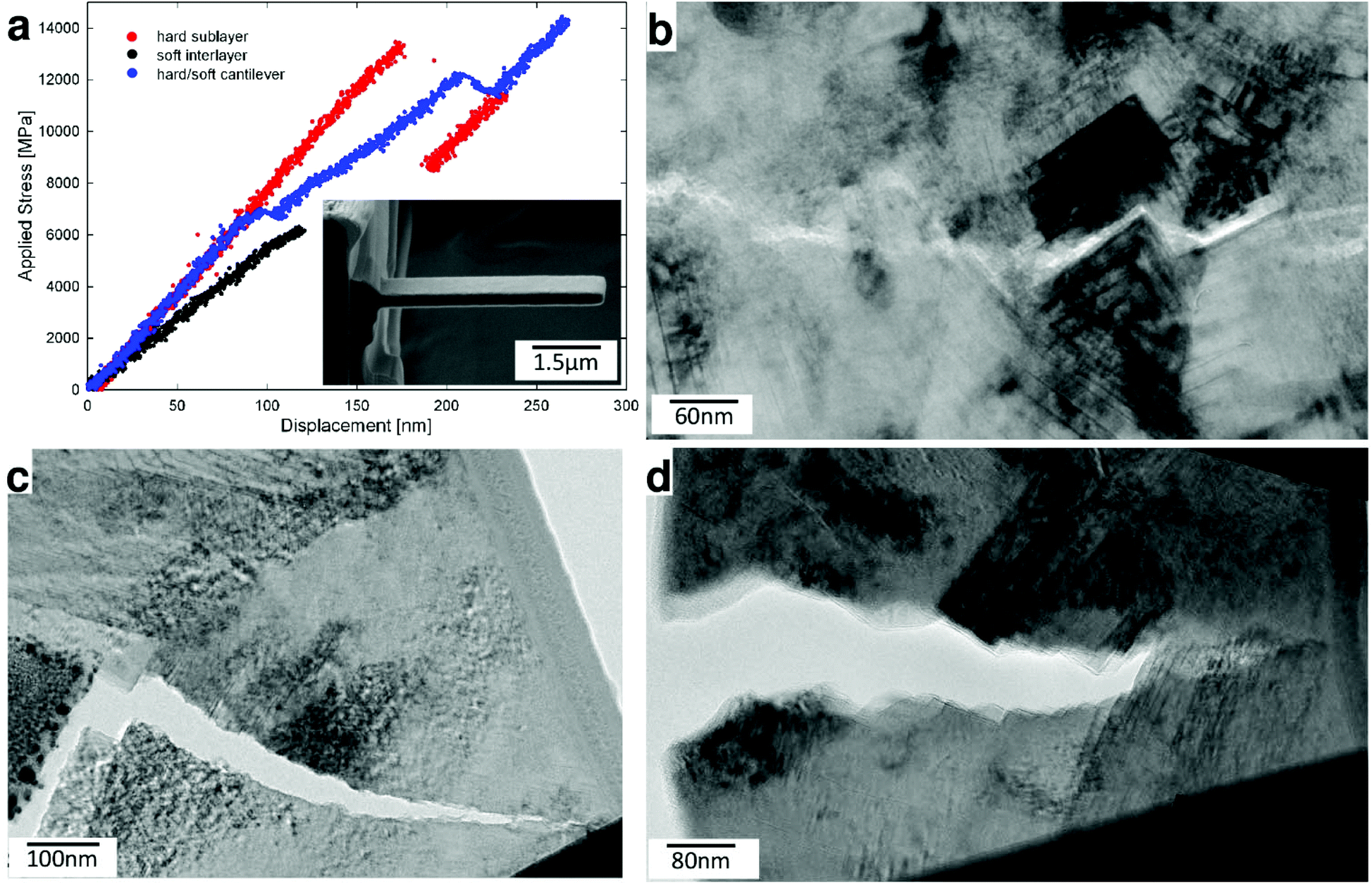
In order to evaluate mechanical properties of the hierarchical thin film, we performed nanoindentation tests and in situ micro- and nanocantilever bending experiments in SEM and TEM.37 The cantilevers were fabricated using focused ion beam (FIB) milling. In addition to the hierarchical thin film, we synthesized also two reference monolithic thin films using constant AlCl3 and TiCl4 precursor partial gas pressures of 0.404 and 0.0909 as well as 0.368 and 0.022, which we further term hard and soft thin films, respectively (cf. Fig. S4†).All three thin films were mechanically tested in order to evaluate the role of the hierarchical architecture on overall mechanical properties and crack propagation behaviour. The hardness of the hierarchical thin film lies between that of the soft and hard monolithic thin films, as this property is mainly given by the intrinsic strength and stiffness of individual constituents (cf.Table 1). Bending experiments on unnotched and notched (Fig. 3a) microcantilevers in SEM (cf. Video S1 of ESI†) were used to determine the respective Young's modulus E, fracture stress σF and fracture toughness KIC of each thin film (Table 1).38,39
 | ||
| Fig. 3 Results from mechanical tests on micro-cantilevers in SEM. (a) An example of a notched cantilever used for toughness characterization. (b) Experimental load-deflection curves from two cantilevers each, fabricated from the hierarchical thin film and from two reference soft and hard thin films. (c–e) Fracture surfaces of reference soft (c), hard (d) films and of the hierarchical films (e). | ||
| Thin film type | Young's modulus E [GPa] | Hardness [GPa] | Fracture stress σF [GPa] | Fracture toughness KIC [MPa m0.5] |
|---|---|---|---|---|
| Soft film | 224 ± 4 | 26 ± 1 | 4.9 ± 0.5 | 3.1 ± 0.2 |
| Hard film | 383 ± 19 | 36 ± 1 | 5.7 ± 0.5 | 4.7 ± 1.0 |
| Hierarchical film | 355 ± 7 | 31 ± 4 | 7.9 ± 0.2 | 4.7 ± 0.4 |
Representative load-deflection curves recorded for six unnotched microcantilevers (two for each thin film type) presented in Fig. 3b indicate dominant linear-elastic response without plastic deformation, as expected for brittle ceramic materials. The evaluated elastic moduli, which are proportional to the slope of the stress-displacement curves in Fig. 3b, approximately follow the rule of mixture and are, similar to hardness, determined by the volume fraction of either elastic or stiff constituents. The evaluated fracture stress and fracture toughness values clearly demonstrate the importance of thin film architecture for the fracture behaviour. Although the fracture toughness of the hierarchical and hard thin films is comparable and significantly higher than that of the soft thin film (Table 1), there is a significant difference in fracture stress. The resistance of the thin films to fracture evidently depends on their architecture, as the fracture stress is by far highest for the hierarchical thin film, reaching a value of 7.9 GPa.
In order to understand this effect, fracture surface (FS) morphologies of the tested microcantilevers were analysed in the SEM. FSs obtained from the soft thin film (Fig. 3c) indicate relatively smooth brittle fracture with a significant fraction of cleaved grains (transgranular fracture, TGF), whereas FSs from the hard thin film (Fig. 3d) show mainly intergranular fracture (IGF) along the boundaries of the large columnar herringbone grains (Fig. 1c). The specific arrangement of the herringbone grains resulted in an increased FS area due to multiple crack deflection events, resulting in a high fracture toughness value (Table 1). Remarkably, FSs of the hierarchical thin film (Fig. 3e) again show relatively smooth brittle fracture with only few micro- and nanoscopic protruding features, very similar to the FSs of the soft thin film, albeit with less TGF.
At the microscopic scale, there are two dominant competing effects which lead to excellent fracture toughness in our films, namely, (i) crack growth and deflection at the grain boundaries of the herringbone crystallites (Fig. 3d) and (ii) crack arrest and deflection at the microscopic interfaces between hard and tough sublayers (Fig. 1a). The fracture stress enhancement in the hierarchical film is caused by the presence of the multi-layered morphology (Fig. 1a), which limits the size of herringbone crystallites (Fig. 1c) and restrains the crack length (Fig. 3e). The equal fracture toughness of the hierarchical film, compared to the hard film, is however a result of the balance between the less pronounced crack deflection at morphologically smaller herringbone crystallites and multiple crack arrests as well as deflections at the interfaces between tough and hard sublayers, which also results in significantly different fracture surface morphologies (cf.Fig. 3d and e).
In order to obtain more insights into the fracture behaviour of our hierarchical thin film at the nanoscale, we fabricated nanocantilevers from various regions of the hierarchical thin film (Fig. 4a, inset), loaded them in TEM using a pico-indentation device and observed the crack propagation in situ, while load-deflection data were simultaneously recorded (cf. Fig. S5†). In Fig. 4a, load-deflection curves from three representative nanocantilevers are shown. Depending on their internal nanostructure, the cantilevers exhibited distinctly different fracture behaviour. The load-deflection curve of a cantilever fabricated (mainly) from a tough interlayer indicates relatively low elastic modulus and fracture stress values, which is in line with the behaviour of the monolithic soft thin film (cf.Fig. 3b).
 | ||
| Fig. 4 Nanomechanical behaviour of the hierarchical thin film. (a) Load-deflection curves from nanocantilevers machined using FIB from soft, hard and soft–hard hierarchical film regions, respectively, and the corresponding cantilever geometry (inset). (b–d) Representative zigzag-like crack patterns showing cleavage (b), transgranular (c) and intergranular/mixed (d) fracture. | ||
On the other hand, the cantilever fabricated from the thin film region consisting of both hard and tough sublayers (containing a significant portion of herringbone crystallites) broke in a stepwise fashion, which is reflected in the jagged load-deflection curve (Fig. 4a). This behaviour is caused by intermittent crack extension, as there are multiple crack deflection and crack arrest events during the cantilever's fracture.
A similar behaviour can be observed in the case of the hard sublayer, however, to a lower extent, which can be explained by the lower level of hierarchy with respect to the specimen containing both hard and soft sublayers. Different fracture mechanisms, occurring during bending of the individual pre-selected regions of the thin films, were revealed by a detailed analysis of the FSs and by studying in situ fracture processes in TEM (cf. Videos S2–S6†). Besides protruding herringbone nano- and micrograins, also mixed IGF, TGF and cleavage fracture (CF) modes occur at various levels of the thin film's hierarchical architecture. IGF takes place along the grain boundaries of the herringbone micrograins and between globular nanograins (Fig. 4d) in hard and tough sublayers, respectively. TGF is found in soft globular nanograins and is equivalent to a combination of IGF between h-Al(Ti)N nanocrystals, CF along the nanolamellar interfaces and CF across c-Ti(Al)N lamellae (Fig. 4c). Additionally, we observed that IGF along the grain boundaries of herringbone crystallites was drawn into and interrupted at the tough interlayers, an effect which is known as the shielding/anti-shielding effect and which is typical for nacre-like microstructures.14,39 CF was further observed mainly along {100} planes of the cubic phases, coinciding with the interfaces of c-Ti(Al)N/c-Al(Ti)N nanolamellae inside the herringbone micrograins (Fig. 4b). Finally, CF infrequently also progressed perpendicular to these interfaces (Fig. 4c), similar to TGF in soft globular nanograins. These latter modes of CF are associated with a high energy release rate, due to the necessity of breaking the strong chemical bonds along coherent interfaces or across single-crystalline cubic platelets, which significantly contribute to an increase of the overall macroscopic fracture toughness. A TEM micrograph in Fig. S5† and in situ TEM videos of ESI† further document the crack propagation behaviour through different regions of the hierarchical thin film, as discussed above.
Based on the SEM and TEM observations, we suggest that the remarkably high fracture stress of the hierarchical nanostructured ceramic thin film (Table 1) originates mainly from (i) the high volume fraction of hard cubic phases and (ii) the shielding/anti-shielding effects across multiple length scales associated with the multiscale alternation of hard/soft phases within the hard/tough thin film sublayers, within micrograins and nanograins as well as hard/tough c-Ti(Al)N/h-Al(Ti)N nanolamellae (cf.Fig. 2).14,39 On the other hand, the high fracture toughness of the complex hierarchical structure is evidently given by a combination of all the described toughening mechanisms and most decisively supported by the latter one.11,14,40
In general, the extraordinary fracture resistance originates from an interplay of various intrinsic toughening mechanisms at multiple length scales and multiple crack deflection events associated with the complex hierarchical nanostructure, despite the brittle nature of the individual ceramic platelets.10,11,41 The importance of the hierarchical nanostructure in the fracture toughness behaviour is also indirectly supported by the quantitative KIC data recently reported from a conventional monolithic TiAlN thin film, which was prepared using magnetron sputtering and which exhibited smaller KIC values even after age hardening.42
High-temperature stability
In addition to mechanical properties, we also investigated thermal stability of our hierarchical nanostructures. Thermal stability up to peak temperatures of ∼1000 °C, reached within ms, is a general requirement in the contact region between coated cutting tool and work piece in the metal cutting industry. Grazing incidence laboratory and cross-sectional synchrotron X-ray diffraction (XRD) analyses validated the phase compositions of the soft, hard and hierarchical thin films as summarized in Fig. 2 (cf. also Fig. S6†). XRD analysis of the hard film with the prevailing c-TiAlN phase was performed in order to investigate the thermal stability of the metastable cubic TiAlN phase and the corresponding nanolamellar microstructure. The film was exposed to temperatures up to ∼1100 °C at a heating rate of 1 K s−1 during in situ high-energy high-temperature grazing-incidence transmission synchrotron XRD with photon energy of 87.1 keV. As shown in Fig. 5 and Fig. S7,† the heating results in the shift of c-TiAlN 111 and 200 reflections (along with a substrate 200 reflection) to smaller diffraction angles due to the crystal lattice expansion up to ∼950 °C. Above this temperature, an onset of cubic phase decomposition and accompanying thin film softening is manifested by an increase in the intensity of the h-TiAlN 100 reflection (Fig. 5e). Additionally, the small-angle X-ray scattering (SAXS) signal (Fig. 5) from the nanolamellae's 2nd order reflection indicates that the cubic nanolamellae start to lose their ordered microstructure above a critical temperature of ∼900 °C as indicated by the SAXS reflection shift to small diffraction angles in Fig. 5f. In comparable conventional TiAlN thin films prepared by magnetron sputtering, the phase decomposition starts usually already at temperatures above ∼800 °C.42–45 In Fig. S7,† corresponding two dimensional X-ray diffraction patterns are presented. We suggest that the high temperature stability of our hierarchical nanostructure in terms of both phase composition and microstructure can be understood in light of their mutually stabilizing interplay. It is supposed that the interfaces between the nanolamellae lower the diffusion rates needed for the formation of the stable soft hexagonal phase, which is observed in polycrystalline TiAlN thin films prepared by magnetron sputtering already from ∼800 °C.42 | ||
| Fig. 5 Thermal stability of the monolithic hard film studied by XRD. (a, b) Debye–Scherrer rings from the film show the presence of hexagonal phase at 1080 °C, as indicated by the arrow. (c, d) Four small-angle X-ray scattering (SAXS) maxima from the herringbone crystallites in c disappear at high temperatures. (e) The evolution of 111 and 200 reflections during heating indicates thermal stability of the c-TiAlN phase up to ∼950 °C and (f) SAXS data show the evolution of the nanolamellae's 2nd order peak (cf. a, c) and the stability of the nanolamellar nanostructure up to ∼900 °C (cf. Fig. S7†). | ||
Discussion and conclusions
In the field of hard thin films, and especially of transition metal nitrides, during the last decades research focused primarily on the understanding of the impact of deposition conditions, multi-layered microstructures, structural defects and various alloying constituents on the thin films’ overall functional behaviour.26,46–48 First-principle calculations were extensively used to predict improved mechanical properties like hardness and toughness in alloyed thin films, but failed to yield significantly improved functionality.26,48 The biomimetic self-assembly approach presented here demonstrates that the application of a hierarchically nanostructured thin film architecture can serve as a very effective concept for the enhancement of toughness, while preserving hardness and thermal stability.11 By using only a simple time-dependent variation of the composition of reactant gases, it is possible to deposit protective bionic thin films with a sequence of nanostructured hierarchical hard/tough sublayers, whereupon synergistic properties can be realized, which are not found in the monolithic structures.The self-assembly mechanism responsible for the formation of the nanolamellar microstructure in CVD TiAlN films is still in dispute.29,31,49 Recent reports suggested that the nanolamellae formation could be a result of a phase separation at the deposition temperature via surface diffusion or kinetically-controlled oscillating reactions at the film surface.30,50,51 The regular morphology of the herringbone crystallites with well-developed {100} interfaces between platelets (Fig. 2) as well as the geometrical and compositional matching at nanolamellar boundaries reported by Zalesak et al.30 in monolithic epitaxial TiAlN films suggest, however, that the nanolamellae's self-assembly is most likely a consequence of kinetically controlled oscillatory reactions at the growing film's surface described already by Bartsch et al.34 In other words, the nanolamellae are formed as a result of a sequential epitaxial overgrowth of {100} facets by individual Al- and Ti-rich sub-layers.30 Depending on the ratio of AlCl3 and TiCl4 precursor gases, however, hard and tough nanostructures are formed with respective coherent c-Ti(Al)N/c-Al(Ti)N and incoherent c-Ti(Al)N/h-Al(Ti)N nanolamellae.
Our six-hierarchy level film self-assembled during ∼15 minutes of deposition time shows simultaneously high hardness, fracture stress and toughness of ∼31 and ∼7.9 GPa and ∼4.7 MPa m0.5, respectively, as well as excellent phase/microstructural stability at high temperatures up to ∼950/900 °C. The experimental jagged load-deflection curves10,11,41 from Fig. 4a clearly demonstrate that the thin film's six-level structural hierarchy induces multiscale crack deflections events (Fig. 4b–d), which result in fracture stress enhancement. The additional level of hierarchy obtained by combining the hard and soft sublayers significantly increases the fracture stress to values 40 and 60% beyond that of the individual constituents, respectively, while fracture toughness remains at least as good as that of the better-performing constituent sublayer. Additional strengthening and toughening mechanisms, induced by this structural enhancement, are responsible for this superior functional performance.11
Biomineralized materials like nacre, bone and enamel represent a typical example of many-level hierarchical materials with a remarkable combination of high fracture toughness and strength up to ∼7 MPa m0.5 and several hundred MPa, respectively.32,52–55 Similarly, biomimetic artificial nacres, bones and teeth were reported with amazing microstructures and mechanical properties18–25 like fracture toughness of 30 MPa m0.5 and yield strengths of 200 MPa in the case of nacre-like poly(methyl methacrylate)-alumina materials.40,56 Since all biomineralized and also most of the biomimetic microstructures include proteins or polymers, however, their application is usually limited to a restricted temperature range.24 Moreover, most of the reported nacre-like microstructures were produced only at the laboratory scale and/or during laborious long-term assembly.18–20,56 In comparison, our hierarchical film can be used at temperatures up to ∼900 °C and the self-assembly process takes just several minutes.
Also in the field of protective thin films, there have been numerous reports on synthetic microstructures with alternating phases and relatively high toughness, which were produced mainly by magnetron sputtering from two or more targets.57–61 Our biomimetic film (Fig. 1) introduces however a novel approach based on multiple hierarchy levels and fast and economic self-assembly in an industrial scale deposition system.
In order to synthesize the hierarchical film with the remarkable hierarchical microstructure from Fig. 1, however, the relatively high deposition temperature of ∼810 °C is needed, which may restrict or limit the use of some substrates (like high speed steel). Therefore, further effort is needed to decrease the temperature of the self-assembly process.
Finally, the employed CVD recipe attracts especially by its high deposition rate of ∼10 μm per hour, simplicity and the ability to produce an applicable industrial material. Therefore, we suggest that further exploration of CVD processes featuring self-assembly reactions holds much promise for incorporation of truly hierarchical biomimetic design into novel application-relevant materials.
Methods
Thin film synthesis
Hierarchical as well as hard and soft monolithic thin films studied in this work were grown with a thickness of ∼2.7, ∼4 and ∼3.8 μm in a commercial Bernex MT-CVD-300 medium temperature reactor at a temperature of ∼810 °C, resulting in a deposition rate of ∼10 μm per hour. The partial pressures of precursors AlCl3, TiCl4, NH3, HCl, N2 as process gases and H2 as the carrier gas were 0.404, 0.09, 0.331, 0.110, 1.653, 22.413 kPa for the thick hard sublayers and 0.368, 0.022, 0.332, 0.113, 1.66, 22.505 kPa for thin tough interlayers, respectively, at a total pressure of 25 kPa. These two sets of parameters were used to prepare also the respective hard and soft monolithic films.Electron microscopy characterization
Zeiss AURIGA CrossBeam and Tescan GAIA3 workstations were used to collect scanning electron microscopy (SEM) micrographs from thin film cross-sections prepared using focused ion beam (FIB) milling. The micro- and nanocantilever fabrication was performed by FIB using an acceleration voltage of 30 kV and currents in the range from 20 nA to 50 pA. Special care was taken to avoid sample damage by Ga ions by using low FIB cutting currents as well as Pt protective layers. High-resolution transmission electron microscopy (TEM) analysis, energy-dispersive X-ray and electron energy loss spectroscopies were performed using a Cs-corrected JEOL JEM-2100F system operated at 200 kV. Conventional TEM was performed using a Philips CM12 system operated at 120 kV.Bending experiments on microcantilevers of 2 × 2 × 10 μm3 in size were performed in a SEM (LEO 982, Zeiss) equipped with an indentation system (PicoIndenter 85, Hysitron). Bending tests on nanocantilevers with a cross-section of ∼1.0 × 0.3 μm2/∼1.0 × 0.5 μm2 and a length of ∼3.5 μm were performed using a Hysitron PI-95 TEM Pico-indenter in a JEOL JEM-2100F microscope operated in conventional (CTEM) mode.
Hardness characterization
Nanoindentation measurements were carried out using a UMIS II (UltraMicro Indentation System) Nanoindenter from Fischer-Cripps Laboratories, equipped with a Berkovich tip and data were evaluated using the Oliver–Pharr method. This particular setup was chosen due to the samples’ high surface roughness, necessitating higher indentation forces and indentation depths.Synchrotron analysis
In situ high-energy high-temperature grazing incidence transmission X-ray diffraction HE-HT-GIT-XRD in the temperature range of 25–1100 °C was performed at the German Synchrotron (DESY) at PETRA III, (beamline P07B side hutch) in transmission geometry with a pencil beam with a size of 400 μm × 100 μm, an incidence angle of 1 degree and a photon energy of 87.1 keV. The samples were mounted on the sample stage of a dilatometer Bähr DIL 805 and heated with a heating rate of 1 K s−1 in high vacuum. Cross-sectional X-ray nanodiffraction experiments were performed at the ID13 beamline of ESRF in Grenoble (F) using an X-ray beam of 100 nm in diameter and an energy of 12.7 keV.Author contributions
J.K., R.P. and J.T. designed the project. M.M. performed micromechanical tests and SEM characterization, high-temperature and cross-sectional synchrotron X-ray diffraction characterization and evaluation. J.Z. performed FIB machining of in situ TEM samples, in situ TEM micromechanical tests and TEM characterisation. R.P. performed coating deposition. B.S. performed FIB machining. M.B., A.S. and N.S. contributed to the synchrotron characterization in Grenoble (ESRF) and in Hamburg (DESY). R.D. contributed to the data interpretation and manuscript preparation. J.F.K. performed conventional TEM characterization. M.L., A.K. and R.W. contributed to the development of CVD process recipes. M.M., J.T. and J.K. wrote the manuscript and coordinated contributions by other authors.Conflicts of interest
The authors declare no conflicts of interest.Acknowledgements
This work was supported by Österreichische Forschungsförderungsgesellschaft mbH (FFG), Project No. 864828, “Tough_TiAlN”. Financial support by the Austrian Federal Government (in particular from Bundesministerium für Verkehr, Innovation und Technologie and Bundesministerium für Wissenschaft, Forschung und Wirtschaft) represented by Österreichische Forschungsförderungsgesellschaft mbH and the Styrian and the Tyrolean Provincial Government, represented by Steirische Wirtschaftsförderungsgesellschaft mbH and Standortagentur Tirol, within the framework of the COMET Funding Programme is gratefully acknowledged. A part of this work was carried out with the support of CEITEC Nano Research Infrastructure (ID LM2015041, MEYS CR, 2016–2019), CEITEC Brno University of Technology.References
- J. W. C. Dunlop and P. Fratzl, Annu. Rev. Mater. Res., 2010, 40, 1–24 CrossRef CAS.
- M. A. Meyers, P.-Y. Chen, A. Y.-M. Lin and Y. Seki, Prog. Mater. Sci., 2008, 53, 1–206 CrossRef CAS.
- P. Fratzl, H. S. Gupta, E. P. Paschalis and P. Roschger, J. Mater. Chem., 2004, 14, 2115–2123 RSC.
- M. Suzuki, K. Saruwatari, T. Kogure, Y. Yamamoto, T. Nishimura, T. Kato and H. Nagasawa, Science, 2009, 325, 1388–1390 CrossRef CAS PubMed.
- M. J. Harrington, A. Masic, N. Holten-Andersen, J. H. Waite and P. Fratzl, Science, 2010, 328, 216–220 CrossRef CAS PubMed.
- N. Kröger, Science, 2009, 325, 1351–1352 CrossRef PubMed.
- Z. Liu, M. A. Meyers, Z. Zhang and R. O. Ritchie, Prog. Mater. Sci., 2017, 88, 467–498 CrossRef CAS.
- P. Fratzl and R. Weinkamer, Prog. Mater. Sci., 2007, 52, 1263–1334 CrossRef CAS.
- J. Sun and B. Bhushan, RSC Adv., 2012, 2, 7617 RSC.
- W. J. Clegg, K. Kendall, N. M. Alford, T. W. Button and J. D. Birchall, Nature, 1990, 347, 455–457 CrossRef CAS.
- R. O. Ritchie, Nat. Mater., 2011, 10, 817–822 CrossRef CAS PubMed.
- B. J. F. Bruet, J. Song, M. C. Boyce and C. Ortiz, Nat. Mater., 2008, 7, 748–756 CrossRef CAS PubMed.
- H. Gao, Int. J. Fract., 2006, 138, 101–137 CrossRef.
- O. Kolednik, J. Predan, F. D. Fischer and P. Fratzl, Adv. Funct. Mater., 2011, 21, 3634–3641 CrossRef CAS.
- B. L. Smith, T. E. Schäffer, M. Viani, J. B. Thompson, N. A. Frederick, J. Kindt, A. Belcher, G. D. Stucky, D. E. Morse and P. K. Hansma, Nature, 1999, 399, 761–763 CrossRef CAS.
- H. Gao, B. Ji, I. L. Jager, E. Arzt and P. Fratzl, Proc. Natl. Acad. Sci. U. S. A., 2003, 100, 5597–5600 CrossRef CAS PubMed.
- P. Fratzl, O. Kolednik, F. D. Fischer and M. N. Dean, Chem. Soc. Rev., 2016, 45, 252–267 RSC.
- Z. Tang, N. A. Kotov, S. Magonov and B. Ozturk, Nat. Mater., 2003, 2, 413–418 CrossRef CAS PubMed.
- S. Elsharkawy, M. Al-Jawad, M. F. Pantano, E. Tejeda-Montes, K. Mehta, H. Jamal, S. Agarwal, K. Shuturminska, A. Rice, N. V. Tarakina, R. M. Wilson, A. J. Bushby, M. Alonso, J. C. Rodriguez-Cabello, E. Barbieri, A. del Río Hernández, M. M. Stevens, N. M. Pugno, P. Anderson and A. Mata, Nat. Commun., 2018, 9, 2145 CrossRef PubMed.
- B. Yeom, T. Sain, N. Lacevic, D. Bukharina, S.-H. Cha, A. M. Waas, E. M. Arruda and N. A. Kotov, Nature, 2017, 543, 95–98 CrossRef CAS PubMed.
- L.-B. Mao, H.-L. Gao, H.-B. Yao, L. Liu, H. Colfen, G. Liu, S.-M. Chen, S.-K. Li, Y.-X. Yan, Y.-Y. Liu and S.-H. Yu, Science, 2016, 354, 107–110 CrossRef CAS PubMed.
- H. L. Gao, S. M. Chen, L. B. Mao, Z. Q. Song, H. Bin Yao, H. Cölfen, X. S. Luo, F. Zhang, Z. Pan, Y. F. Meng, Y. Ni and S. H. Yu, Nat. Commun., 2017, 8, 287 CrossRef PubMed.
- X. F. Pan, H. L. Gao, Y. Lu, C. Y. Wu, Y. D. Wu, X. Y. Wang, Z. Q. Pan, L. Dong, Y. H. Song, H. P. Cong and S. H. Yu, Nat. Commun., 2018, 9, 1–8 CrossRef PubMed.
- U. G. K. Wegst, H. Bai, E. Saiz, A. P. Tomsia and R. O. Ritchie, Nat. Mater., 2015, 14, 23–36 CrossRef CAS PubMed.
- X. Wang, S. Xu, S. Zhou, W. Xu, M. Leary, P. Choong, M. Qian, M. Brandt and Y. M. Xie, Biomaterials, 2016, 83, 127–141 CrossRef CAS PubMed.
- P. H. Mayrhofer, R. Rachbauer, D. Holec, F. Rovere and J. M. Schneider, in Comprehensive Materials Processing, 2014, vol. 4, pp. 355–388 Search PubMed.
- K. Choy, Prog. Mater. Sci., 2003, 48, 57–170 CrossRef CAS.
- J. Todt, R. Pitonak, A. Köpf, R. Weißenbacher, B. Sartory, M. Burghammer, R. Daniel, T. Schöberl and J. Keckes, Surf. Coat. Technol., 2014, 258, 1119–1127 CrossRef CAS.
- J. Todt, J. Zalesak, R. Daniel, R. Pitonak, A. Köpf, R. Weißenbacher, B. Sartory, C. Mitterer and J. Keckes, Surf. Coat. Technol., 2016, 291, 89–93 CrossRef CAS.
- J. Zalesak, D. Holec, I. Matko, M. Petrenec, B. Sartory, N. Koutná, R. Daniel, R. Pitonak and J. Keckes, Acta Mater., 2017, 131, 391–399 CrossRef CAS.
- A. Paseuth, K. Yamagata, A. Miura, M. Higuchi and K. Tadanaga, J. Am. Ceram. Soc., 2017, 100, 343–353 CrossRef CAS.
- R. Z. Wang, Z. Suo, A. G. Evans, N. Yao and I. A. Aksay, J. Mater. Res., 2001, 16, 2485–2493 CrossRef CAS.
- H. Gao, B. Ji, I. L. Jager, E. Arzt and P. Fratzl, Proc. Natl. Acad. Sci. U. S. A., 2003, 100, 5597–5600 CrossRef CAS PubMed.
- K. Bartsch, A. Leonhardt and E. Wolf, Metall. Coatings Thin Film, 1992, vol. 1992, pp. 193–197 Search PubMed.
- I. Petrov, P. B. Barna, L. Hultman and J. E. Greene, J. Vac. Sci. Technol., A, 2003, 21, S117–S128 CrossRef CAS.
- A. Madan, I. W. Kim, S. C. Cheng, P. Yashar, V. P. Dravid and S. A. Barnett, Phys. Rev. Lett., 1997, 78, 1743–1746 CrossRef CAS.
- G. Dehm, B. N. Jaya, R. Raghavan and C. Kirchlechner, Acta Mater., 2018, 142, 248–282 CrossRef CAS.
- K. Matoy, H. Schönherr, T. Detzel, T. Schöberl, R. Pippan, C. Motz and G. Dehm, Thin Solid Films, 2009, 518, 247–256 CrossRef CAS.
- B. J. F. Bruet, H. J. Qi, M. C. Boyce, R. Panas, K. Tai, L. Frick and C. Ortiz, J. Mater. Res., 2005, 20, 2400–2419 CrossRef CAS.
- E. Munch, M. E. Launey, D. H. Alsem, E. Saiz, A. P. Tomsia and R. O. Ritchie, Science, 2008, 322, 1516–1520 CrossRef CAS PubMed.
- D. Sen and M. J. Buehler, Sci. Rep., 2011, 1, 35 CrossRef CAS PubMed.
- M. Bartosik, C. Rumeau, R. Hahn, Z. L. Zhang and P. H. Mayrhofer, Sci. Rep., 2017, 7, 16476 CrossRef CAS PubMed.
- S. PalDey and S. Deevi, Mater. Sci. Eng., A, 2003, 342, 58–79 CrossRef.
- P. H. Mayrhofer, A. Hörling, L. Karlsson, J. Sjölén, T. Larsson, C. Mitterer and L. Hultman, Appl. Phys. Lett., 2003, 83, 2049–2051 CrossRef CAS.
- M. Bartosik, R. Daniel, Z. Zhang, M. Deluca, W. Ecker, M. Stefenelli, M. Klaus, C. Genzel, C. Mitterer and J. Keckes, Surf. Coat. Technol., 2012, 206, 4502–4510 CrossRef CAS PubMed.
- G. Greczynski, J. Lu, J. Jensen, I. Petrov, J. E. Greene, S. Bolz, W. Kölker, C. Schiffers, O. Lemmer and L. Hultman, Thin Solid Films, 2014, 556, 87–98 CrossRef CAS.
- H. Kindlund, D. G. Sangiovanni, L. Martínez-de-Olcoz, J. Lu, J. Jensen, J. Birch, I. Petrov, J. E. Greene, V. Chirita and L. Hultman, APL Mater., 2013, 1, 042104 CrossRef.
- P. H. Mayrhofer, C. Mitterer, L. Hultman and H. Clemens, Prog. Mater. Sci., 2006, 51, 1032–1114 CrossRef CAS.
- J. Keckes, R. Daniel, C. Mitterer, I. Matko, B. Sartory, A. Koepf, R. Weißenbacher and R. Pitonak, Thin Solid Films, 2013, 545, 29–32 CrossRef CAS.
- F. Uny, S. Achache, S. Lamri, J. Ghanbaja, E. Fischer, M. Pons, E. Blanquet, F. Schuster and F. Sanchette, Surf. Coat. Technol., 2019, 358, 923–933 CrossRef CAS.
- F. Pacher, P. H. Mayrhofer and D. Holec, Surf. Coat. Technol., 2017, 326, 37–44 CrossRef CAS.
- F. Barthelat, C.-M. Li, C. Comi and H. D. Espinosa, J. Mater. Res., 2006, 21, 1977–1986 CrossRef CAS.
- L. H. He and M. V. Swain, J. Mech. Behav. Biomed. Mater., 2008, 1, 18–29 CrossRef PubMed.
- K. J. Koester, J. W. Ager and R. O. Ritchie, Nat. Mater., 2008, 7, 672–677 CrossRef CAS PubMed.
- S. Bechtle, S. F. Ang and G. A. Schneider, Biomaterials, 2010, 31, 6378–6385 CrossRef CAS PubMed.
- S. Deville, E. Saiz, R. K. Nalla and A. P. Tomsia, Science, 2006, 311, 515–518 CrossRef CAS PubMed.
- J. M. Lackner, W. Waldhauser, B. Major, L. Major and M. Kot, Thin Solid Films, 2013, 534, 417–425 CrossRef CAS.
- J. Xu, X. Zhao, P. Munroe and Z. Xie, Sci. Rep., 2014, 4, 1–8 Search PubMed.
- M. Schlögl, C. Kirchlechner, J. Paulitsch, J. Keckes and P. H. Mayrhofer, Scr. Mater., 2016, 68, 917–920 CrossRef.
- P. C. Wo, X. L. Zhao, P. R. Munroe, Z. F. Zhou, K. Y. Li, D. Habibi and Z. H. Xie, Acta Mater., 2013, 61, 193–204 CrossRef CAS.
- R. Hahn, M. Bartosik, R. Soler, C. Kirchlechner, G. Dehm and P. H. Mayrhofer, Scr. Mater., 2016, 124, 67–70 CrossRef CAS.
Footnote |
| † Electronic supplementary information (ESI) available: SEM, TEM, CSnanoXRD and HT-XRD. See DOI: 10.1039/c8nr10339a |
| This journal is © The Royal Society of Chemistry 2019 |