DOI:
10.1039/C8NR10332A
(Paper)
Nanoscale, 2019,
11, 4959-4969
On the decay time of upconversion luminescence†
Received
21st December 2018
, Accepted 18th February 2019
First published on 19th February 2019
Abstract
In this study, we systematically investigate the decay characteristics of upconversion luminescence (UCL) under anti-Stokes excitation through numerical simulations based on rate-equation models. We find that a UCL decay profile generally involves contributions from the sensitizer's excited-state lifetime, energy transfer and cross-relaxation processes. It should thus be regarded as the overall temporal response of the whole upconversion system to the excitation function rather than the intrinsic lifetime of the luminescence emitting state. Only under certain conditions, such as when the effective lifetime of the sensitizer's excited state is significantly shorter than that of the UCL emitting state and of the absence of cross-relaxation processes involving the emitting energy level, the UCL decay time approaches the intrinsic lifetime of the emitting state. Subsequently, Stokes excitation is generally preferred in order to accurately quantify the intrinsic lifetime of the emitting state. However, possible cross-relaxation between doped ions at high doping levels can complicate the decay characteristics of the luminescence and even make the Stokes-excitation approach fail. A strong cross-relaxation process can also account for the power dependence of the decay characteristics of UCL.
Introduction
Lanthanide-doped upconversion nanoparticles (UCNPs), as unique spectral converters, that convert low-energy excitation photons into high-energy emitted photons at relatively low excitation intensity,1 have attracted considerable interest in the areas of biotechnology, information technology, photonics and energy.2–7 The last two decades have witnessed tremendous advances in upconversion nanochemistry, which have led to easy synthetic access to UCNPs with a well-controlled size and phase, sophisticated core–shell structures, and surface properties.8 In particular, the studies of modulating upconversion luminescence (UCL) using chemical methods have reached the sub-nanometer level, represented by attempts of manipulating energy transfer between lanthanide dopants in delicate core–shell structures and even on a sub-lattice scale.9–13 Each UCNP contains commonly multiple optically active trivalent rare-earth ions with manyfolds of accessible long-lived energy states. The mutual interactions (mainly non-radiative Förster-type energy transfer processes) between these optically active centers make them operate as an integrated unit, leading to the complex luminescence kinetics of each nanoparticle.14,15 The decay kinetics of UCL is one of the most important aspects of its temporal characteristics, and a deep understanding of this property is of great significance, not only for characterizing and optimizing UCNPs, but also for extending their applications.15–17
Despite the importance of both the material development and applications, there is still a lack of a comprehensive understanding and an elucidation of the UCL decay characteristics. In the studies of UCL decay characteristics, an anti-Stokes excitation approach, i.e., excitation at longer wavelengths/lower energies in comparison with the emission, is often utilized. In a typical measurement, UCNPs are excited by a short-pulse or a square-wave near infrared (NIR) laser beam, e.g., λexc = 980 nm, and the decay profile of the generated UCL band is recorded. After the exponential fitting of the decay profile data, the decay time constant is extracted. This decay time is often interpreted/regarded as the intrinsic lifetime of the UCL emitting state,17,18 although it is known that the recorded UCL decay profile typically involves contributions from the lifetimes of the intermediate states,19,20e.g., the sensitizer's excited-state lifetime and the energy migration between the different sensitizer ions. The preconditions and extent of the influence of these processes have not been investigated and clarified in detail. In addition, there is a lack of a clear understanding of other phenomena like the excitation-intensity independence or dependence of the UCL lifetime observed in different upconversion nanosystems.17,21,22
In this study, we use numerical simulations based on rate-equation models to systematically investigate how the radiative properties of intermediate states affect the decay profile of UCL under varying conditions, aiming at evaluating to which extent the experimentally extracted decay time represents the intrinsic lifetime of the UCL emitting state. In addition, experimental studies on the UCL decay of a series of upconversion nanorods are carried out to examine the validity of the conclusions obtained from our simulations. Our work provides a deep understanding of UCL decay characteristics and will have ramifications in many relevant applications, e.g., in UCNP-based Förster resonant energy transfer (FRET) biosensing, where determination of the luminescence lifetime of the UCNP donor is critical in order to quantify the FRET efficiency.23
Model and methods
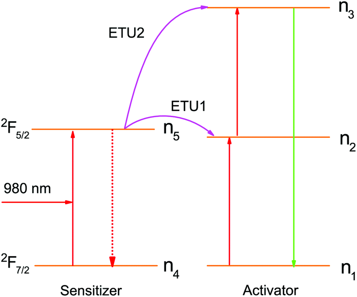
A standard two-photon upconversion mechanism is considered in our simulation studies (Fig. 1) in order to provide general insights into the decay properties of UCL. In this upconversion system, the sensitizer has a two energy-level structure, which can represent the most extensively used sensitizer, namely Yb3+, while the activator has a simplified three-level structure. Energy transfer upconversion (ETU), from the sensitizer to the activator, is considered as the primary upconversion mechanism. In this typical two-photon upconversion process, the activator ion in the ground state (state 1) is first excited to state 2 through an ETU process (ETU1), and further excited to state 3 through a second ETU process (ETU2). The upconversion luminescence is generated from the transition 3 → 1. The time-dependent populations of different energy states can be described by the following rate equations:24| |  | (1) |
| |  | (2) |
| |  | (3) |
| |  | (4) |
| |  | (5) |
where ni (i = 1–5) denotes the population of ions at different states, nA(S) is the number density of the activator (sensitizer) ions, τi (j = 2, 3, 5) is the lifetime of the excited energy state, and σ is the absorption cross-section of the sensitizer ions for the transition 4 → 5, respectively. ρ(t) is the time-dependent excitation intensity function, h is the Planck's constant, v is the frequency of the excitation light, resonant with the transition 4 → 5, and W1 and W2 represent the rate constants of the energy transfer processes, ETU1 and ETU2, respectively. Note that transition 3 → 2 is neglected in this model.
 |
| | Fig. 1 Energy transfer upconversion (ETU) mechanism for the standard two-photon upconversion luminescence. | |
The response of the upconversion system to a low repetition-rate nanosecond pulse excitation function (a rectangular shape, 10 Hz, 100 ns) resonant with transition 4 → 5 was subsequently simulated. The induced temporal evolution of the UCL originating from the transition 3 → 1 was then compared with the decay profile of the luminescence solely determined by the intrinsic lifetime of the emitting state (τ3). These time-resolved rate equations were solved numerically using the commercially available software Matlab. In the simulations, parameter values were selected or estimated based on the reported values in the literature and were varied on purpose to imitate different upconversion systems, in order to investigate their influence on the decay time of the UCL.
Experimental
Syntheses of NaYF4:Yb3+/Er3+ nanorods
In a typical synthesis, stoichiometric stock solutions (0.2 M) of Y(NO3)3, Yb(NO3)3, and Er(NO3)3 were added into a mixture of an aqueous solution of NaOH (1.875 mL, 5 M), oleic acid (6.25 mL) and ethanol (6.25 mL) in a 50 mL centrifuge tube. The mixture was then heated up to 50 °C and thoroughly stirred for 20 min. An aqueous solution of NH4F (1.25 mL, 2 M) was subsequently added, and the mixture was stirred for 20 min. Subsequently, the milky colloidal solution was transferred to a 50 mL Teflon-lined autoclave and heated to 220 °C and remained for 12 h. The product was allowed to cool down to room temperature. The nanorods were precipitated by the addition of ethanol, followed by centrifugation at 7500 rpm for 5 min. The obtained nanorods were washed several times using ethanol and cyclohexane and were finally re-dispersed in cyclohexane for subsequent use.
Luminescence kinetics measurements
Luminescence measurements were performed with a commercially available Edinburgh Instruments setup (FLS980) with multichannel scaling equipped with a 980 nm (8 W) laser diode for measurements of the upconversion luminescence (ETU from Yb3+ to Er3+) and the downconversion emission of Yb3+ and with a 485 nm pulsed laser for direct excitation of the downconversion Er3+ emission. A F-G03 R2658P photomultiplier in a cooled housing with an extended spectral range was used for signal detection.
TEM
TEM images were taken on an electron microscope (JEM-2100HR, JEOL).
Results and discussion
Influence of the lifetimes of intermediary states
We investigated how the radiative properties of the intermediate states, i.e. the excited state of the sensitizer (state 5) and the intermediate state of the activator (state 2), affect the decay profile of the UCL under varying conditions.
The influence of the sensitizer's excited-state lifetime (τ5) was first studied. The average excitation power density of the nanosecond pulse excitation function (a rectangular shape, 10 Hz, 100 ns) was kept at 1 W cm−2, corresponding to a peak power density of 1 MW cm−2. This excitation function was used throughout this work unless otherwise specified. Table 1 summarizes the constant parameters used in the simulations.
Table 1 Summary of the constant parameters used in the simulations of studying the effect of the sensitizer's excited-state lifetime
|
σ (cm2) |
n
S (cm−3) |
n
A (cm−3) |
τ
2 (ms) |
τ
3 (ms) |
W
1 (cm3 s−1) |
W
2 (cm3 s−1) |
|
Modified from Liu et al.25
Estimated from Liu et al.25
Modified from Villanueva-Delgado et al.26
Modified from Jung et al.27
Modified from Liu et al.25 and Bansal et al.28
|
1.5 × 10⁻²⁰![[thin space (1/6-em)]](https://www.rsc.org/images/entities/char_2009.gif) a a |
1.5 × 10²¹a |
1.5 × 10²⁰b |
1.32c |
0.2d |
2.5 × 10⁻¹⁸e |
5 × 10⁻¹⁷e |
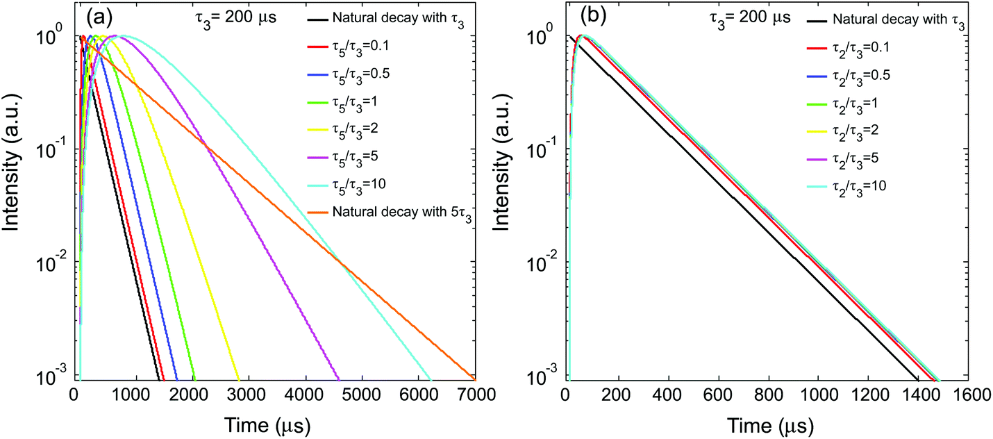
Fig. 2a shows the simulated temporal evolutions of the UCL under conditions of different τ5/τ3 ratios, benchmarked with the natural decay curve solely determined by the intrinsic lifetime of the emitting state (τ3), i.e., e−t/τ3. In the simulations, τ3 was fixed at 200 μs, a typical lifetime value for the two-photon UCL band of Er3+ at 540 nm.27 The sensitizer's excited-state lifetime (τ5) was varied over a large range (0.1τ3–10τ3) to cover as many values reported in the literature.29,30 As shown in Fig. 2a, when the sensitizer's excited-state lifetime (τ5) is significantly smaller than τ3, the decay behavior of UCL can be well represented by its natural decay characterized by τ3 (Fig. 2a). With increasing τ5, the induced UCL decay starts to gradually deviate from its natural decay (Fig. 2a). When τ5/τ3 ≥ 2, the UCL decay becomes apparently slower than its natural decay. When τ5/τ3 reaches 10, the UCL decay profile can approach an exponential decay curve characterized by a time constant of τ5/2 (or 5τ3) (Fig. 2a). These results reveal that the kinetics of the UCL from the upper excited state of the activator is latently influenced by the sensitizer's excited-state lifetime to a varying extent under different conditions. This could make the anti-Stokes excitation approach for the UCL intrinsic lifetime measurement invalid.
 |
| | Fig. 2 (a) Simulated UCL (from state 3) decay profiles under short-pulse upconversion excitation with different τ5/τ3. (b) UCL decay profiles under short-pulse upconversion excitation with different τ2/τ3. | |
Next, we studied the influence of the lifetime of the intermediate state of the activator (τ2) on the decay behavior of the UCL. In the simulations, the parameter values in Table 1 were otherwise used, except that τ2 was varied and that τ5 was set to a significantly smaller value (0.02 ms) than τ3 to eliminate its influence on the extraction of τ3. Here, τ2 was also varied in a relatively large range (0.1τ3–10τ3). In a previous study by Gamelin et al. on singly doped two-photon upconversion systems, where the chemically identical lanthanide ions act as both sensitizers and activators,19 it was found that the decay of the transient n3 population lasts substantially longer than its natural decay and has a time constant of half of the intermediate-state lifetime (τ2) when the upper state has a significantly shorter lifetime than the intermediate state. Here, we examined if the same conclusion holds true in the current upconversion system. Fig. 2b presents the simulated decay profiles of the UCL with varying τ2, benchmarked with the natural decay curve solely determined by the intrinsic lifetime of the emitting state (τ3), i.e., e−t/τ3. Interestingly, when τ5 was set to 0.02 ms, τ2, even if varying in a large range, no noticeable change was observed in the UCL decay behavior. With increasing τ5, the variation of τ2 starts to cause a non-negligible change in the UCL decay curve, as shown in Fig. S1,† but the change is much less significant than that caused by the variation of the sensitizer's excited-state lifetime, τ5. This result is quite different from that found in singly doped two-photon upconversion systems,19 indicating that the sensitizer's excited state is the key time-limiting intermediate state for the upconversion system depicted in Fig. 1.
Influence of energy transfer
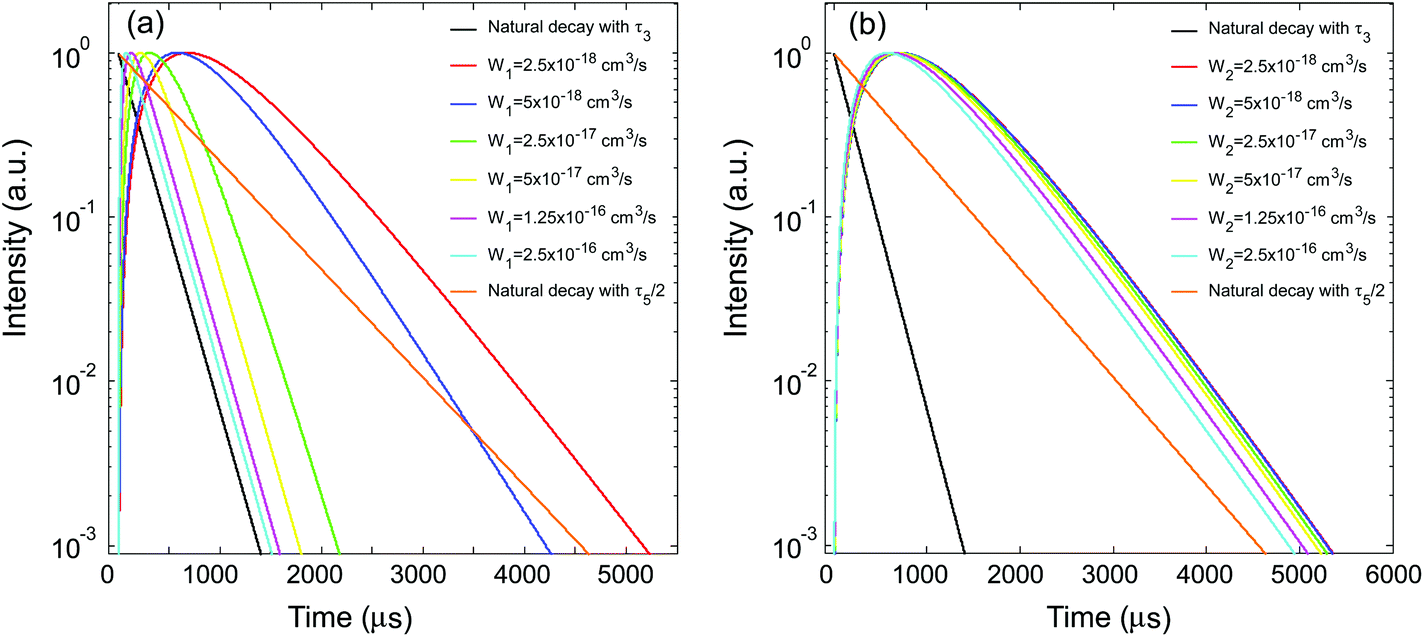
Subsequently, the influence of the energy transfer coefficient of ETU1, W1, was investigated. During the simulations, W1 was varied to span two orders of magnitude (2.5 × 10⁻¹⁸–2.5 × 10⁻¹⁶ cm3 s−1) based on previously reported values,28,30–32 while the other parameters remained constant as in Table 1, and with τ5 set to a value (1.32 ms) significantly longer than τ3. According to the result shown in Fig. 2a, this long τ5 was supposed to retard the decay of the UCL, making it remarkably slower than its natural decay. Fig. 3a presents the simulated decay profiles of the UCL with varied W1, benchmarked with the natural decay profile determined from the intrinsic lifetime of the emitting state (τ3), i.e., e−t/τ3. Interestingly, due to energy transfer, the excitation energy can apparently propagate throughout the network of interacting lanthanide ions and regulate the influence of the sensitizer's excited-state lifetime. When the energy transfer was weak (i.e., a small W1 value), the overall decay profile of the UCL could not be represented by the natural decay profile of the emitting state, approaching an exponential decay curve described by a time constant of τ5/2 instead (Fig. 3a). With gradually increasing W1, the overall decay behavior was asymptotic to the natural decay profile of state 3, with the influence of the long excited-state lifetime of the sensitizer fading out (Fig. 3a). Note that in real upconversion systems an increased energy transfer rate could be related to a decreased distance between the two participants, thus dependent on the dopant concentrations.
 |
| | Fig. 3 (a) Simulated UCL (from state 3) decay profiles under short pulse excitation with different W1. (b) UCL (from state 3) decay profiles under short pulse excitation with different W2. | |
The influence of the energy transfer coefficient of ETU2, W2, was also investigated using constant parameters as in Table 1, with τ5 = τ2 and now varying W2. In marked contrast to the effect of W1, the overall decay behavior was relatively insensitive to the variation of W2, where the influence of the long excited-state lifetime of the sensitizer (τ5) indicated in Fig. 2a was always present and thus the decay time of the UCL could not be represented by its intrinsic lifetime (Fig. 3b).
Correlation with the analytical expression
We find that the decay behavior of the UCL can be well correlated to our results from a previous work, where the response of the standard two-photon upconversion system to a short excitation pulse was theoretically studied.15 With some assumptions, the impulse response function (IRF) of the standard two-photon UCL was obtained (ESI text 1 in ref. 15):| |  | (8) |
with τ′5 given by| |  | (9) |
which can be regarded as the effective decay lifetime of the sensitizer excited state, containing contributions of both radiative decay and nonradiative energy transfer; n5(0) is the population of state 5 immediately after the end of the short excitation pulse. As indicated by eqn (8), the UCL decay profile could be fitted by bi-exponential relaxation with contributions of the decay terms e−t/τ3 and e−2t/τ′5, characterized by the time constants of τ3 and τ′5/2, respectively. The limiting time constant especially in the long-time limit is affected by the relative magnitudes of τ3 and τ′5/2 (regulated by the weights of the corresponding decay components), with the larger one standing out. Under weak energy transfer conditions (namely, small W1), τ′5 can be well approximated by τ5 according to eqn (9). In this regime, if τ5/2 is significantly smaller than τ3, τ3 will be the dominant decay time constant for the long-time range, otherwise, τ5/2 will be the limiting time constant. This analysis is in line with the simulated results shown in Fig. 2a. In many Yb3+-sensitized UCNPs, the lifetime of the Yb3+ excited state (corresponding to τ5) is often found to be a few times longer than those of two-photon UCL emitting states.30,33 Thus, the half of the Yb3+ excited state lifetime (a few hundreds of microseconds to milliseconds30,33) would be often the limiting time constant for the UCL decay. Note, this does not completely exclude the other possibility that the half of the (effective) Yb3+ excited state lifetime is smaller than the intrinsic lifetime of the UCL emitting state in certain systems so that the latter becomes dominant in the UCL decay.
Under elevated energy transfer conditions (increasing W1), the energy transfer process would start to regulate the effect of τ5 and lead to a decreasing limit of the decay time constant τ′5/2. It can be speculated that when the energy transfer is efficient enough τ′5/2 becomes smaller than τ3, and the latter becomes the dominant decay time constant for the long-time range (even if when τ5 is significantly larger than τ3). This prediction correlates well with the data shown in Fig. 3a. In addition, it should be noted that the ground state population of the activator, n1, is in the same position as the ETU1 rate constant (W1) in determining τ′5 by eqn (9). Thus, it is supposed to play a similar role in regulating the influence of τ5 on the decay behavior of the UCL. This is confirmed by further simulated results obtained with varying activator doping concentrations (nA) (Table S1 and Fig. S2†), considering n1 ≈ nA.15
The numerically simulated results and theoretical analyses jointly disclose that (the half of) the effective decay lifetime of the sensitizer excited state and the intrinsic decay lifetime of the UCL emitting state co-determine the UCL decay behavior and compete to be the limiting time constant, with the larger one winning out. In addition, the energy transfer from the sensitizer to the activator, providing a deactivation channel for the sensitizer, leads to a decreased effective decay lifetime of the sensitizer excited state, in favor of the win of the intrinsic decay lifetime of the UCL emitting state.
Influence of cross-relaxation between activator ions
In the above calculations, the radiative transition (3 → 1) is the only depopulation channel for state 3. In real upconversion systems, other depopulation channels could exist due to interionic interactions, e.g., cross-relaxation between activator ions, especially when the doping level is high.34 Therefore, we investigated the influence of possible cross-relaxation between the activator ions on the decay behavior of the UCL. The two-photon upconversion model used is illustrated in Fig. 4, where a cross-relaxation process marked with CR is included in the standard two-photon upconversion model shown in Fig. 1.
 |
| | Fig. 4 Energy transfer upconversion (ETU) mechanism for two-photon upconversion luminescence with the presence of a cross-relaxation process. | |
By including the CR process, the rate eqn (1)–(3) describing the population kinetics of states 1, 2 and 3 can be modified into:
| |  | (10) |
| |  | (11) |
| |  | (12) |
where
C denotes the rate constant for the CR process. During the simulations,
C was varied in a large range, and
W1 was set to 2.5 × 10
−16 cm
3 s
−1, while other parameters remained constant as in
Table 1. Here,
W1 was set in the strong energy transfer regime to be able to filter out the influence of the sensitizer's excited-state lifetime (
τ5) on the decay properties of the UCL (
Fig. 3a).
Fig. 5a presents the simulated decay profiles of the UCL with varied
C, benchmarked with the natural decay curve solely determined by the intrinsic lifetime of the emitting state (
τ3),
i.e.,
e−t/τ3. Apparently, an increasing CR coefficient induces a decay behavior that is faster than its natural decay. This trend is expected considering that the CR process introduces an additional depopulation channel for state 3 with a rate scaled with
Cn1 as indicated in
eqn (12), analogous to the natural decay pathway. The occurrence of a CR process depopulating the UCL emitting state will thus undoubtedly affect the intrinsic lifetime measurement of the emitting state under upconversion excitation conditions.
 |
| | Fig. 5 Decay profiles of UCL from state 3 under short pulse excitation with different cross-relaxation coefficients. | |
Excitation power density effect
Previous experimental work has shown that the UCNP lifetimes are roughly independent of the excitation power density for some UCNPs especially at low powers,17,18 but become pronouncedly dependent on the excitation power density for UCNPs at higher excitation power densities, particularly at values required for single-nanocrystal measurements.21,22 This encouraged us to subsequently examine the effect of the excitation power density.
The model shown in Fig. 1 and the corresponding rate equations (eqn (1)–(7)) were first studied. During the simulations, the peak power density of the excitation pulse (a rectangular shape, 10 Hz, 100 ns) was varied over a very large range (102–109 W cm−2). Here, the minimum excitation intensity (100 W cm−2) can be easily achieved under spectroscopic measurement conditions using spectrofluorometers,24 while the maximum excitation intensity (1 GW cm−2) is even several orders of magnitude higher than that achieved on a confocal microscope.34 Other parameters remained constant as in Table 1, with τ5 = τ2. Also, the rate constant for the ETU1 process, W1, was set to 2.5 × 10⁻¹⁶ cm3 s−1, which is in the strong energy transfer regime, in which the influence of the long lifetime of the sensitizer excited state on the UCL decay behavior can be eliminated through efficient energy transfer. Fig. 6a presents the simulated decay profiles of the UCL with varied excitation peak power density. As seen, the UCL decay profiles are nearly independent of the excitation power density in the long-time limit, having a similar time constant to the natural decay (Fig. 6a), which is consistent with previous reports.17,18 Only peak power densities higher than 100 MW cm−2 could cause a noticeable delay in the onset of the fast decay behavior of the UCL, but without leading to a noticeable change in the decay profile itself in the long-time limit (Fig. 6a).
 |
| | Fig. 6 UCL (from state 3) decay profiles under short pulse excitation with different peak power densities: (a) without cross-relaxation and (b) with cross-relaxation. | |
Cross-relaxation processes prevail in upconversion systems, especially in those doped with high-concentration activator ions. Next, we used the same fixed parameter values as in achieving Fig. 6a but included a relatively strong cross-relaxation process, with a coefficient of C = 2.5 × 10⁻¹⁶ cm3 s−1,28 to investigate how the excitation power-density affects the decay behavior in such a system. Eqn (4)–(7) and (10)–(12) were used to calculate the decay behavior of the UCL under pulsed excitation (a rectangular shape, 10 Hz, 100 ns) with different peak intensities. Fig. 6b presents the simulated decay profiles of the UCL. As can be seen, the influence of the excitation peak power density is negligible at irradiation level below 1 × 10⁶ W cm−2. With further increasing the excitation peak power density, the UCL decay becomes noticeably slower in the long-time limit (Fig. 6b). This is understandable according to eqn (12). The CR process introduces an additional depopulation channel to the emitting state described by the term −Cn1n3, where the rate is given by the product of the CR coefficient (C) and the population density of the ground state of the activator (n1). With increasing excitation intensity, the activator ground state population would decrease, because more ions are pumped to excited states. This would lead to a smaller coefficient for this CR-induced depopulation channel, resulting in slower decays. It can be inferred that if another CR-induced depopulation channel exists (between the UCL emitting state and another excited state, nx, if present), the decay of the UCL would become faster with increasing excitation power densities, as the rate for this additional depopulation channel increases due to a probable increase of nx. In addition, a higher peak power density above 1 × 10⁸ W cm−2 in this case causes an even more noticeable delay in the onset of the fast decay behavior (Fig. 6b) than in the absence of the CR process.
Based on these results and reasoning, it is reasonable to argue that the lifetime dependence of the UCL on the excitation intensity can to a large extent be attributed to the presence of CR processes involving the upconversion emitting state, because the contribution of these CR processes to the depopulation of the UCL emitting state depends on the population of the other participating energy state, which is generally dependent on the excitation intensity.
Direct excitation conditions
The above studies reveal that the decay of the UCL under anti-Stokes excitation conditions often involves the contribution of the sensitizer's excited-state lifetime, except in the strong energy transfer regime. This suggests that the widely used Stokes excitation approach, i.e., direct excitation to the target emitting state, should be preferred to measure the decay profile and extract the intrinsic lifetime of the target state, as illustrated in Fig. 7a.
 |
| | Fig. 7 (a) Luminescence kinetics under Stokes excitation without the presence of cross-relaxation and (b) with the presence of cross-relaxation. | |
Under Stokes excitation, the population kinetics of the involved energy states can be described by the following rate equations:
| |  | (13) |
| |  | (14) |
where
σd is the absorption cross-section of activator ions for transition 1 → 3;
ρd(
t) is the time-dependent excitation intensity function of the Stokes-excitation laser beam;
vd is the frequency of the Stokes-excitation light. Indicated by
eqn (13) and (14), the decay profile obtained in this situation would be solely determined by the intrinsic lifetime of state 3. However, this Stokes excitation approach may only be valid for upconversion systems with low doping levels. With increased concentration of the dopants, the effect of lanthanide ion–lanthanide ion interactions,
e.g., the cross-relaxation between activator ions as shown in
Fig. 7b, has to be taken into account. This complicates the decay behavior of state 3 and makes it deviate from its natural decay.
The decay profile of the UCL under Stokes excitation with the presence of a cross-relaxation process was modeled using the following rate equations:
| |  | (16) |
| |  | (17) |
| |  | (18) |
During the simulations, the cross-relaxation coefficient C was varied in a large range of 2.5 × 10⁻¹⁸–2.5 × 10⁻¹⁶ cm3 s−1, based on the previously reported coefficient values.30,31,34,35 The other parameters remained constant as listed in Table 1, and with σd = 1.5 × 10⁻²¹ cm2. The average excitation power density of the nanosecond pulse excitation function (a rectangular shape, 10 Hz, 100 ns) was kept as 1 W cm−2, corresponding to a peak power density of 1 MW cm−2.
Fig. 8 presents the simulated decay profiles of the UCL with varied C, benchmarked with the natural decay curve solely determined by the intrinsic lifetime of the emitting state (τ3), i.e., e−t/τ3. As can be clearly seen, similarly an increasing CR coefficient induces a faster decay behavior than its natural decay, as observed in those UC-excitation cases. This reveals that the presence of a CR process, typically prevailing in high-doping upconversion systems, makes the intrinsic lifetime measurement for the UCL emitting state troublesome even for a Stokes-excitation approach.
 |
| | Fig. 8 UCL decay profiles under short-pulse Stokes excitation with different cross-relaxation coefficients C. | |
Experimental examples
Influence of the Yb3+ sensitized-state lifetime on the UCL decay time.
Although the standard two-photon ETU UCL scheme shown in Fig. 1 is simple, it can represent and model many Yb3+ sensitized two-photon UC emission bands, including the green emissions of Er3+ ions (2H11/2/4S3/2 → 4I15/2) in Yb3+/Er3+ codoped nanoparticles, the green emissions of Ho3+ ions (5S2/5F4 → 5I8) in Yb3+/Ho3+ codoped nanoparticles, and the NIR emission of the Tm3+ ions (3H4 → 3H6) in Yb3+/Tm3+ codoped nanoparticles, referring to the detailed rate-equation analysis based on more sophisticated models in sections S1–S3 in the ESI of ref. 24. For instance, when describing the green UC emissions of Er3+ ions (2H11/2/4S3/2 → 4I15/2) in Yb3+/Er3+ codoped nanoparticles, states 1, 2 and 3 in Fig. 1 would represent the Er3+ 4I15/2 state (ground state), the 4I11/2 state (intermediate state) and the coupled states 4F7/2/2H11/2/4S3/2, respectively.24 In these systems, the lifetime of the sensitizer excited state (the Yb3+ 2F5/2 state) would exert an influence on the decay behavior of the UC luminescence. Our above theoretical analysis predicts that only when the half of the effective lifetime of the Yb3+ 2F5/2 state is significantly smaller than that of the UCL emitting state, the same luminescence decay time could be expected under UC and Stokes excitation conditions, both approaching the intrinsic lifetime of the emitting state.
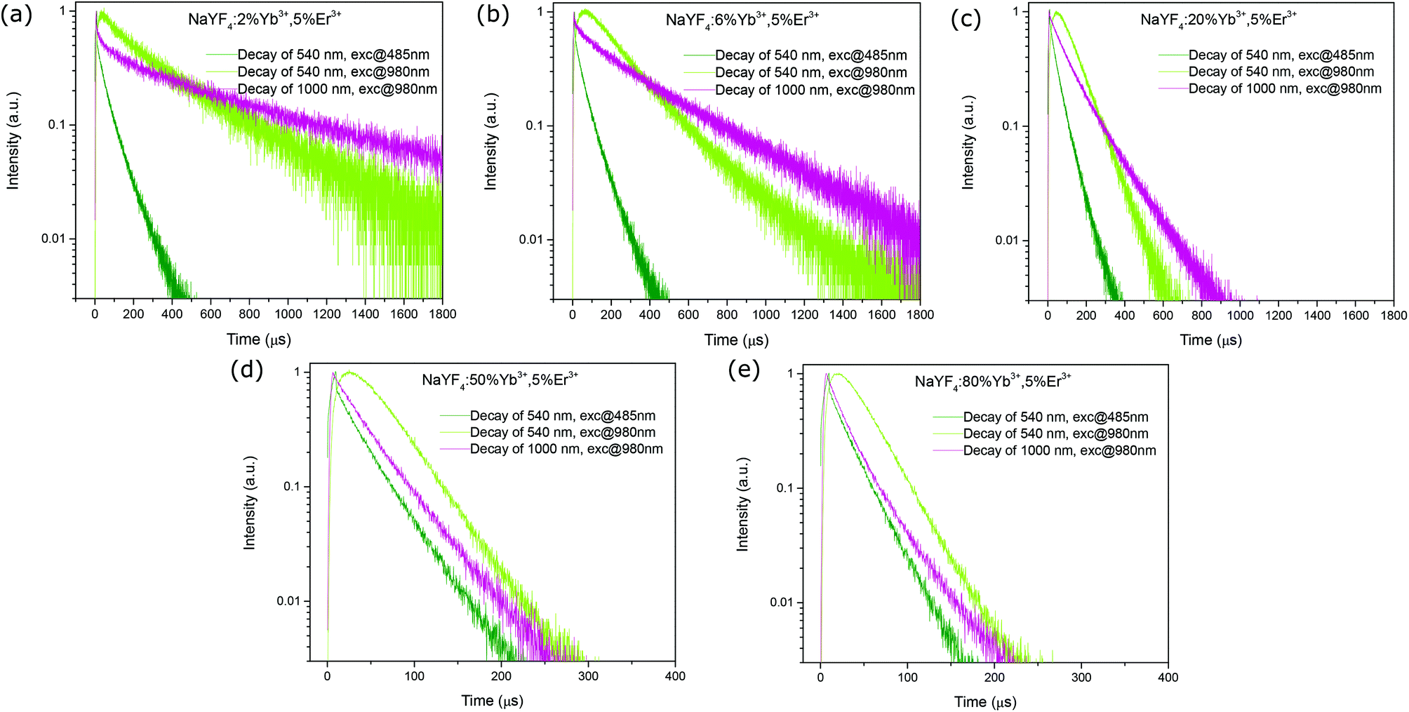
In order to test our prediction, a series of NaYF4:x% Yb3+,5% Er3+ (x = 2, 6, 20, 50, 80) nanorods were synthesized using a hydrothermal method (TEM images shown in Fig. S3†),36 and the decay profiles of the green emission band of Er3+ at around 540 nm (4S3/2 → 4I15/2) were measured under short-pulse UC excitation (@980 nm) and Stokes excitation (@485 nm). The intention of varying the Yb3+ concentration while fixing the Er3+ concentration was to change the effective lifetime of the Yb3+ excited state and thus to regulate its influence on the UCL decay time. Fig. 9 presents the decay profiles of the Er3+ green emission (4S3/2 → 4I15/2) of different samples under UC and Stokes excitations. As seen, for samples with the Yb3+ doping concentration no more than 20% (Fig. 9a and b), the measured Yb3+ excited state lifetime (emission at 1000 nm, excited at 980 nm) is much longer than that of the Er3+ 4S3/2 state (emission at 540 nm, excited at 485 nm). This leads to a significantly slower luminescence decay under UC excitation than that under Stokes excitation, revealing the influence of the Yb3+ excited-state lifetime. With the increasing Yb3+ doping concentration, the contrast between the Yb3+ excited state lifetime and the Er3+ 4S3/2 state lifetime becomes less prominent, evidenced by their decay trends (Fig. 9c), and the UCL decay accordingly becomes closer to the downconversion luminescence decay (Fig. 9c). At very high Yb3+ concentrations, the Yb3+ excited state lifetime approaches that of the Er3+ 4S3/2 state (Fig. 9d and e). As a result, the UCL decay becomes asymptotic to the downconversion luminescence decay. These observations support well our theoretical predictions. Here, the decreasing Yb3+ excited state effective lifetime with the increasing Yb3+ concentration can be ascribed to two factors: (1) the increasing energy-transfer strength from Yb3+ to Er3+, given that the Yb3+ → Er3+ energy transfer rate is highly dependent on the distance between the two participants and thus the dopant concentrations; (2) the increasing surface quenching effect assisted by the Yb3+ network.20,37,38
 |
| | Fig. 9 Measured room-temperature luminescence decay profiles of the Er3+ green emission (4S3/2 → 4I15/2) of different upconversion nanorod samples, (a) NaYF4:2% Yb3+, 5% Er3+, (b) NaYF4:6% Yb3+, 5% Er3+, (c) NaYF4:20% Yb3+, 5% Er3+, (d) NaYF4:50% Yb3+, 5% Er3+, and (e) NaYF4:80% Yb3+, 5% Er3+, under UC (exc@980 nm, 5 μs, 500 Hz) and direct (exc@485 nm, 5 μs, 500 Hz) short-pulse excitations, as well as the decay profiles of the Yb3+ 1000 nm emission (2F5/2 → 2F7/2) under 980 nm excitation (5 μs, 500 Hz). | |
Influence of activator → sensitizer energy back transfer on the emission decay under Stokes excitation.
Our above simulations reveal that cross-relaxation processes between activator ions at high doping concentrations make the intrinsic lifetime measurement for the target emitting state troublesome even for a Stokes-excitation approach. In a similar way, another mechanism could also disturb the intrinsic lifetime measurement of the target emitting state, i.e., energy back transfer from the sensitizer in the UCL emitting state to the sensitizer in the ground state,39,40 which introduces an additional depopulating channel to the target emitting state. We measured the decay profiles of the green emission band of Er3+ at around 540 nm (4S3/2 → 4I15/2) under short-pulse Stokes excitation (@485 nm) for a series of NaYF4:x% Yb3+, 5% Er3+ (x = 2, 6, 20, 50, 80) nanorod samples, as shown in Fig. 10. As can be seen, with an Yb3+ concentration exceeding 6%, the Er3+ 540 nm emission exhibits a decreasing decay lifetime, indicating the effect of Er3+ → Yb3+ energy back transfer, i.e., 4S3/2 (Er3+) + 2F7/2 (Yb3+) → 4I15/2 (Er3+) + 2F5/2 (Yb3+).24 Otherwise, a similar Er3+ emission lifetime is expected for these samples due to the same doping concentration of Er3+ ions (indicating a similar extent of Er3+–Er3+ interactions) and similar morphologies of these nanorods (Fig. S3†).
 |
| | Fig. 10 Measured room-temperature decay profiles of the Er3+ green emission (4S3/2 → 4I15/2) of different upconversion nanorod samples (NaYF4:x% Yb3+, 5% Er3+, x = 2, 6, 20, 50, 80) under Stokes short-pulse excitation (exc@485 nm, 5 μs, 500 Hz). | |
Based on this study, we can argue that the decay time of the UCL extracted from the emission temporal evolution measurement, should in general be interpreted as the overall temporal response of the upconversion system to the excitation function, instead of the intrinsic lifetime of the emitting state. The extent to which the measured decay time reflects the intrinsic lifetime of the emitting state is highly dependent on the upconversion mechanism, and thus the composition of the nanoparticles. In order to accurately extract the intrinsic lifetime of UCL, thorough measurements are generally required than merely using decay profile measurements, to firstly identify the upconversion pathway, and then quantify the contributions of different relaxation channels of the emitting state.
It is found that the half of the Yb3+ excited state lifetime could often be the limiting time constant for UCL decay due to its large value, typically ranging from a few hundreds of microseconds to milliseconds. This particularly has ramifications in UCNP-based FRET biosensing, where UCNPs are mainly used as FRET donors. In such applications, the change of the apparent decay time of the UCL, measured under upconversion excitation conditions, was often found to be very insignificant with the presence of acceptors. Indicated by the present study, it was quite probable that in these circumstances the time constant of the Yb3+ excited state was being measured instead of the lifetime of the UCL emitting state. This calls for a better approach to quantify the FRET efficiency other than measuring the UCL decay time under 980 nm excitation.
Conclusions
In conclusion, the decay time extracted from the upconversion luminescence (UCL) decay profile generally cannot be interpreted as the intrinsic lifetime of the UCL emitting state. Instead, it is an overall temporal response of the whole upconversion system to the excitation function, influenced by the sensitizer's excited-state lifetime and the effects of energy transfer and cross-relaxation. Only when the half of the lifetime of the sensitizer's excited state is significantly shorter than that of the UCL emitting state, the UCL decay time can well represent the emitting-state intrinsic lifetime. Stokes excitation is generally desired when measuring the intrinsic lifetimes of lanthanide energy states. However, cross-relaxation between doped ions complicates the decay properties of the luminescence originating from the target state even under Stokes excitation, something that needs to be carefully addressed. Strong cross-relaxation processes can also explain the occurrence of an excitation power density dependence of UCL decay.
Conflicts of interest
There are no conflicts to declare.
Acknowledgements
H.L. acknowledges a Starting Grant (2016-03804) provided by the Swedish Research Council (Vetenskapsrådet). H.Å. acknowledges a grant (2016-03619) from the Swedish Research Council (Vetenskapsrådet). Part of this work was supported by the COST Action CM1403 The European Upconversion Network From the Design of Photon-Upconverting Nanomaterials to Biomedical Applications. This work was supported by the National Natural Science Foundation of China (61675071), the Guangdong Provincial Science Fund for Distinguished Young Scholars (2018B030306015), the Pearl River S and T Nova Program of Guangzhou (201710010010), and the open fund of the State Key Laboratory of Modern Optical Instrumentation of Zhejiang University (No. MOIKF201801).
References
- F. Auzel, Chem. Rev., 2004, 104, 139–173 CrossRef CAS PubMed.
- K.-C. Liu, Z.-Y. Zhang, C.-X. Shan, Z.-Q. Feng, J.-S. Li, C.-L. Song, Y.-N. Bao, X.-H. Qi and B. Dong, Light: Sci. Appl., 2016, 5, e16136–e16136 CrossRef CAS PubMed.
- R. Deng, F. Qin, R. Chen, W. Huang, M. Hong and X. Liu, Nat. Nanotechnol., 2015, 10, 237–242 CrossRef CAS PubMed.
- X. Liu, R. Deng, Y. Zhang, Y. Wang, H. Chang, L. Huang and X. Liu, Chem. Soc. Rev., 2015, 44, 1479–1508 RSC.
- J. He, W. Zheng, F. Ligmajer, C.-F. Chan, Z. Bao, K.-L. Wong, X. Chen, J. Hao, J. Dai, S.-F. Yu and D. Y. Lei, Light: Sci. Appl., 2017, 6, e16217–e16217 CrossRef CAS PubMed.
- F. Wang, S. Wen, H. He, B. Wang, Z. Zhou, O. Shimoni and D. Jin, Light: Sci. Appl., 2018, 7, 18007 CrossRef CAS.
- Q. Zhan, J. Qian, H. Liang, G. Somesfalean, D. Wang, S. He, Z. Zhang and S. Andersson-Engels, ACS Nano, 2011, 5, 3744–3757 CrossRef CAS PubMed.
- G. Chen, H. Ågren, T. Y. Ohulchanskyy and P. N. Prasad, Chem. Soc. Rev., 2015, 44, 1680–1713 RSC.
- X. Chen, L. Jin, W. Kong, T. Sun, W. Zhang, X. Liu, J. Fan, S. F. Yu and F. Wang, Nat. Commun., 2016, 7, 10304–10304 CrossRef CAS PubMed.
- J. Wang, R. R. Deng, M. A. MacDonald, B. L. Chen, J. K. Yuan, F. Wang, D. Z. Chi, T. S. A. Hor, P. Zhang, G. K. Liu, Y. Han and X. Liu, Nat. Mater., 2014, 13, 157–162 CrossRef CAS PubMed.
- Y. Zhong, I. Rostami, Z. Wang, H. Dai and Z. Hu, Adv. Mater., 2015, 27, 6418–6422 CrossRef CAS PubMed.
- B. Zhou, L. Tao, Y. Chai, S. P. Lau, Q. Zhang and Y. H. Tsang, Angew. Chem., Int. Ed., 2016, 55, 12356–12360 CrossRef CAS PubMed.
- Q. Chen, X. Xie, B. Huang, L. Liang, S. Han, Z. Yi, Y. Wang, Y. Li, D. Fan, L. Huang and X. Liu, Angew. Chem., Int. Ed., 2017, 56, 7605–7609 CrossRef CAS PubMed.
- H. Liu, K. Huang, R. R. Valiev, Q. Zhan, Y. Zhang and H. Ågren, Laser Photonics Rev., 2017, 12, 1700144 CrossRef.
- H. Liu, M. K. G. Jayakumar, K. Huang, Z. Wang, X. Zheng, H. Ågren and Y. Zhang, Nanoscale, 2017, 9, 1676–1686 RSC.
- J. Pichaandi, J. C. Boyer, K. R. Delaney and F. C. J. M. van Veggel, J. Phys. Chem. C, 2011, 115, 19054–19064 CrossRef CAS.
- Y. Lu, J. Zhao, R. Zhang, Y. Liu, D. Liu, E. M. Goldys, X. Yang, P. Xi, A. Sunna, J. Lu, Y. Shi, R. C. Leif, Y. Huo, J. Shen, J. A. Piper, J. P. Robinson and D. Jin, Nat. Photonics, 2014, 8, 32–36 CrossRef CAS.
- J. Zhao, Z. Lu, Y. Yin, C. McRae, J. A. Piper, J. M. Dawes, D. Jin and E. M. Goldys, Nanoscale, 2013, 5, 944–952 RSC.
-
D. Gamelin and H. Gudel, in Transition Metal and Rare Earth Compounds, ed. H. Yersin, Springer Berlin/Heidelberg, 2001, vol. 214, pp. 1–56 Search PubMed.
- K. Huang, H. Liu, M. Kraft, S. Shikha, X. Zheng, H. Ågren, C. Würth, U. Resch-Genger and Y. Zhang, Nanoscale, 2018, 10, 250–259 RSC.
- D. J. Gargas, E. M. Chan, A. D. Ostrowski, S. Aloni, M. V. P. Altoe, E. S. Barnard, B. Sanii, J. J. Urban, D. J. Milliron, B. E. Cohen and P. J. Schuck, Nat. Nanotechnol., 2014, 9, 300–305 CrossRef CAS PubMed.
- B. Chen, Y. Liu, Y. Xiao, X. Chen, Y. Li, M. Li, X. Qiao, X. Fan and F. Wang, J. Phys. Chem. Lett., 2016, 7, 4916–4921 CrossRef CAS PubMed.
- D. Geißler, S. Linden, K. Liermann, K. D. Wegner, L. J. Charbonnière and N. Hildebrandt, Inorg. Chem., 2014, 53, 1824–1838 CrossRef PubMed.
- H. Liu, C. T. Xu, D. Lindgren, H. Xie, D. Thomas, C. Gundlach and S. Andersson-Engels, Nanoscale, 2013, 5, 4770–4775 RSC.
- H. Liu, C. T. Xu, G. Dumlupinar, O. B. Jensen, P. E. Andersen and S. Andersson-Engels, Nanoscale, 2013, 5, 10034–10040 RSC.
- P. Villanueva-Delgado, D. Biner and K. W. Krämer, J. Lumin., 2016, 189, 84–90 CrossRef.
- T. Jung, H. L. Jo, S. H. Nam, B. Yoo, Y. Cho, J. Kim, H. M. Kim, T. Hyeon, Y. D. Suh, H. Lee and K. T. Lee, Phys. Chem. Chem. Phys., 2015, 17, 13201–13205 RSC.
- A. Bansal, H. Liu, M. K. G. Jayakumar, S. Andersson-Engels and Y. Zhang, Small, 2016, 12, 1732–1743 CrossRef CAS PubMed.
- Z. Wang and A. Meijerink, J. Phys. Chem. C, 2018, 122, 26298–26306 CrossRef CAS PubMed.
- R. B. Anderson, S. Smith, P. S. May and M. T. Berry, J. Phys. Chem. Lett., 2014, 5, 36–42 CrossRef CAS PubMed.
- S. E. Ivanova, A. M. Tkachuk, A. Mirzaeva and F. Pelle, Opt. Spectrosc., 2008, 105, 228–241 CrossRef CAS.
- A. Braud, S. Girard, J. L. Doualan, M. Thuau, R. Moncorg'e and A. M. Tkachuk, Phys. Rev. B: Condens. Matter Mater. Phys., 2000, 61, 5280–5292 CrossRef CAS.
- M. Y. Hossan, A. Hor, Q. Luu, S. J. Smith, P. S. May and M. T. Berry, J. Phys. Chem. C, 2017, 121, 16592–16606 CrossRef CAS.
- Q. Zhan, H. Liu, B. Wang, Q. Wu, R. Pu, C. Zhou, B. Huang, X. Peng, H. Ågren and S. He, Nat. Commun., 2017, 8, 1058–1058 CrossRef PubMed.
- A. M. Tkachuk, S. E. Ivanova, M. F. Joubert and Y. Guyot, Opt. Spectrosc., 2005, 99, 932–949 CrossRef CAS.
- F. Wang, J. Wang and X. Liu, Angew. Chem., Int. Ed., 2010, 49, 7456–7460 CrossRef CAS PubMed.
- B. Huang, J. Bergstrand, S. Duan, Q. Zhan, J. Widengren, H. Ågren and H. Liu, ACS Nano, 2018, 12, 10572–10575 CrossRef CAS PubMed.
- C. Würth, S. Fischer, B. Grauel, A. P. Alivisatos and U. Resch-Genger, J. Am. Chem. Soc., 2018, 140, 4922–4928 CrossRef PubMed.
- G. Chen, G. Somesfalean, Y. Liu, Z. Zhang, Q. Sun and F. Wang, Phys. Rev. B: Condens. Matter Mater. Phys., 2007, 75, 195204–195204 CrossRef.
- J. Zhang, Z. Hao, J. Li, X. Zhang, Y. Luo and G. Pan, Light: Sci. Appl., 2015, 4, e239–e239 CrossRef CAS.
Footnote |
| † Electronic supplementary information (ESI) available. See DOI: 10.1039/c8nr10332a |
|
| This journal is © The Royal Society of Chemistry 2019 |
Click here to see how this site uses Cookies. View our privacy policy here. 
 Open Access Article
 This Open Access Article is licensed under a Creative Commons Attribution-Non Commercial 3.0 Unported Licence
 d,
Ute
Resch-Genger
d,
Ute
Resch-Genger