 Open Access Article
Creative Commons Attribution 3.0 Unported Licence
Thermoelectric properties of oligoglycine molecular wires†
Songjun
Hou
,
Qingqing
Wu
*,
Hatef
Sadeghi
 and
Colin J.
Lambert
 *
*
Quantum Technology Centre, Department of Physics, Lancaster University, LA1 4YB Lancaster, UK. E-mail: c.lambert@lancaster.ac.uk; q.wu6@lancaster.ac.uk
First published on 2nd January 2019
Abstract
We have investigated the electrical and thermoelectrical properties of glycine chains with and without cysteine terminal groups. The electrical conductance of (Gly)n, (Gly)nCys and Cys(Gly)nCys molecules (where Gly, Cys represent glycine and cysteine and n = 1–3) was found to decay exponentially with length l as e−βl. Our results show that connecting the molecules to gold electrodes via the sulphur atom of the cysteine moiety leads to higher β factors of 1.57 Å−1 and 1.22 Å−1 for (Gly)nCys and Cys(Gly)nCys respectively, while β = 0.92 Å−1 for (Gly)n. We also find that replacing the peptide bond with a methylene group (–CH2–) increases the conductance of (Gly)3Cys. Furthermore, we find the (Gly)1Cys and Cys(Gly)1Cys systems show good thermoelectrical performance, because of their high Seebeck coefficients (∼0.2 mV K−1) induced by the sulphur of the cysteine(s). With the contributions of both electrons and phonons taken into consideration, a high figure of merit ZT = 0.8 is obtained for (Gly)1Cys at room temperature, which increases further with increasing temperature, suggesting that peptide-based SAM junctions are promising candidates for thermoelectric energy harvesting.
Introduction
Understanding electron transport through biomolecules is important, because they play central roles in cellular respiration, photosynthesis and enzymatic reactions.1–7 Although much effort has been devoted to transport in peptides,8,9 the exact mechanism of charge transport through peptides and proteins is still under debate. Generally, it is accepted that quantum tunnelling through molecular orbitals is the dominant mechanism for short peptide chains10,11 and consequently their electrical conductance G decays exponentially with length as G = Ae−βl,12,13 where the prefactor A is a constant reflecting the molecule-electrode coupling strength, l is the separation between two electrodes and β is an attenuation constant. In an early work, it was reported that the attenuation factor β of cysteamine–(glycine)n–cysteine β (1.1 ± 0.1 per atom or 0.87 ± 0.7 Å−1) is nearly the same with that of alkanedithiol (1.0 ± 0.01 per atom) in a single-molecule measurement.14 On the other hand, in self-assembly monolayers (SAMs) of cysteine–(glycine)n it was demonstrated that oligoglycines have a smaller β factor (0.50 ± 0.02 per atom) and are more conductive than alkanedithiols (0.94 ± 0.02 per atom).10 After excluding the effect of the interactions between different peptide chains (e.g. hydrogen bonds) in the SAM, it was concluded that the interaction between the highest occupied amide orbitals in the single strand is the origin of the lower β factor. In contrast, scanning tunnelling microscope-based break-junction (STM-BJ) measurements15 revealed that the peptides of (alanine)n and (glycine)n without external anchors have greater β factors (0.93 ± 0.04 Å−1 and 0.97 ± 0.01 Å−1) and are less conductive than the corresponding alkane chain (0.75 ± 0.02 Å−1), due to the presence of tightly bound electronic states located at the peptide bond, which reduce the energy of orbitals relative to Fermi energy and the coupling to leads.In the above measurements, although the main constituent is (glycine)n, different moieties (cysteamine (HS(CH2)2NH2), cysteine (HS(CH2)2(COOH)NH2), amine group (–NH2), carboxylate group (–COO–)) are adopted as anchors, with the thiol group in cysteamine and cysteine used to connect the backbone to electrode. Anchors are expected have significant influence on the charge transport properties in molecular device,16–19 because the couplings between the molecule and the electrodes and alignment of molecular energy levels and the Fermi level of electrodes will change as anchors are modified. For example conducting atomic force microscope (AFM) measurements of anchor–(CH2)n–anchor chains19 demonstrate that the anchor groups have weak influence on the decay constant β. However, in oligoacene conducting probe atomic force microscopy (CP-AFM) measurements, the β factor of oligoacenedithiol (0.2 Å−1) is half that of oligoacenemonothiol (0.5 Å−1).18 Recently, it was demonstrated that additional electronic states due to thiol anchor groups can significantly decrease the value of β in alkane–phenyl molecular junctions.20 Consequently, the effect of anchors on conductance and tunnelling attenuation factor β for different molecule systems should be investigated.
In this letter, to understand the origin of the high attenuation factor shown in Tao's work,14 we report the effect of anchor groups on the transport properties of single-molecule oligoglycine junctions. Furthermore, since high-β-factor molecules are known to have high Seebeck coefficients,21–23 the thermoelectric properties of oligoglycine are investigated, to assess their potential to harness waste energy and generate electricity via the Seebeck effect. Inorganic thermoelectric materials such as Pb, Bi, Co, Sb are toxic and expensive due to limited global sources, which make them unattractive for a wide use.24 Therefore, in recent years, different strategies have been proposed to exploit the thermoelectric properties of nanostructured organic materials or organic molecules.25–28 Single-molecule devices provide a possible building block for constructing high-efficiency thermoelectric power generators.29 However, to our knowledge, there are few reports about the thermoelectric properties of peptides. In the present work, we find that connecting to electrodes via sulphur anchor groups leads to higher β factors of 1.57 Å−1, 1.22 Å−1 and 0.92 Å−1 for (Gly)nCys, Cys(Gly)nCys and (Gly)n respectively. It is also found that replacing the peptide bond with a methylene group could increase the conductance of single-(G)3C molecular junctions. In addition, we find the (Gly)nCys and Cys(Gly)nCys systems show good thermoelectrical properties with high Seebeck coefficients (∼0.2 mV K−1) induced by the sulphur in cysteine. Furthermore, after considering both the phonon and electron contributions, for (Gly)1Cys a high figure of merit ZT ≈ 0.8 could be obtained at room temperature, which increases further as the temperature increases.
Results and discussion
Usually, three ways are used to bind peptide molecules to gold electrode: through alkyl thiols,30,31 through thiol-contained amino acids (cysteines)10,14,32 or through the “N-terminal” and “C-terminal” residues.15 Here, we adopt the latter two methods, since they allow investigation of charge transport properties without introducing external groups. Fig. 1 shows the junction conformations investigated below. In Fig. 1(a), oligoglycine (Gly)n (n = 1–3) is connected to gold electrodes directly, where one end is –COO−, which could be achieved when the solution pH is 7 or higher,33 and the other is –NH2. Based on the molecules in Fig. 1(a), in Fig. 1(b) oligoglycine (Gly)n is connected to gold electrodes through the thiol group incorporated in cysteine–peptide residues. For Fig. 1(c), two cysteines are attached to the oligoglycine (Gly)n system at both ends, where the thiol groups serve as anchors.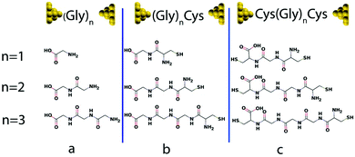 | ||
| Fig. 1 Au–molecule–Au junctions of oligoglycine system with three different anchors. Gly and Cys stand for glycine and cysteine separately and n = 1–3. (a) Oligoglycine connected to gold electrodes directly. (b) Oligoglycine connected to gold electrodes by cysteine–peptide molecule where sulphur is the anchor atom. (c) Oligoglycine with two ends of cysteine connected to gold electrodes. For each series, the molecular structures (n = 1–3) are shown below (for detailed structures used in simulations see Fig. S1†). | ||
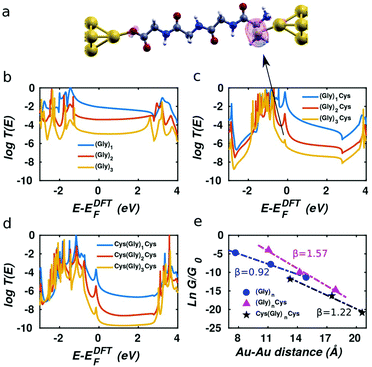
After computing the electron transmission functions T(E) of these junctions (see methods), the low temperature electrical conductance G is given by G = G0T(EF), where G0 is the conductance quantum and EF is the Fermi energy of the electrodes (see methods for the room-temperature formula). The computed transmission curves T(E) of the junctions in Fig. 1 are presented in Fig. 2. The DFT-predicted Fermi energy EDFTF of (Gly)n is close to middle of the gap between the highest occupied molecular orbital (HOMO) and the lowest unoccupied molecular orbital (LUMO), while the Fermi energies of (Gly)nCys and Cys(Gly)nCys systems are located close to HOMO, because of the influence of the sulphur.34 Since the Fermi energy of glycine–peptide-based junctions lies close to the HOMO, this means that charge transport in glycine–peptide-based junctions is hole-mediated, in agreement with the literature.15,30,35
This phenomenon is demonstrated by the local density of states (LDOS) near the resonance of between −0.5 eV and 0 shown in Fig. 2a for molecule (Gly)3Cys. The magenta surface shows that the weight of the LDOS corresponding to the peak indicated by the arrow in Fig. 2(c) is mainly located on the sulphur atom. Similar features are observed in Fig. 2(c) and (d), where sulphur atoms are also present.
As the number of glycines increases from one to three for the three short peptide series with different anchor groups shown in Fig. 1, the distance between the two gold-apex atoms in the pyramids of electrodes increases and the conductance of the junctions decreases. Since the Fermi energy is located within the HOMO–LUMO gap, charge transfer takes place via off resonant tunnelling36 and as shown in Fig. 2e, the conductance decays exponentially with distance is expected. After fitting the logarithm of the room-temperature conductance to a linear function and extracting the β factor for each series, we find that the β parameter for (Gly)n system is the smallest at 0.92 Å−1, which agrees quite well with the result reported in literature,15 while the (Gly)nCys system has β = 1.57 Å−1 and the Cys(Gly)nCys has β = 1.22 Å−1, both of which are higher than the β factor of (Gly)n system. This difference between the β factors of junctions with thiol and dithiol anchor groups has been reported in oligoacene systems.18 We also note that the three calculated β factors are all greater than that of the oligoglycine-based SAM conductance measurements of Baghbanzadeh et al.10 For each series, we obtain lower β factors after replacing the peptide bond in the middle of the molecules with –CH2– group, indicating the peptide chain is less conductive than the saturated alkane chain (see Fig. S2 and S3† for more information).
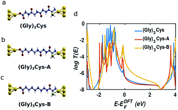
In order to obtain further insight into the mechanism of charge transport through peptide backbones, we investigated the effect of substituting the peptide bonds with methylene groups, as shown on the top of Fig. 3. These molecules were investigated experimentally in ref. 10. In Fig. 3a–c, the molecules sandwiched in junctions are: (Gly)3Cys, (Gly)3Cys with one peptide substituted by two –CH2– groups (denoted (Gly)3Cys-A) and (Gly)3Cys with two peptides substituted by four –CH2– groups (denoted (Gly)3Cys-B). Their corresponding transmissions are plotted in Fig. 3d. We find that the transmission does not change significantly when replacing one peptide with two methylene groups, while the transmission increases rapidly when two peptide bonds are substituted. This shows that the lone pairs of electrons in oxygen and nitrogen atoms in oligopeptides do not enhance the single-molecule conductance compared with fully saturated alkane chains, which is consistent with literature results for oligoglycines without external sulphur anchors.15 The similar phenomena of heteroatom substitution is found in oligoethers, where the conductance of alkanedithiols decreases after substituting every third –CH2– group with O or S,37,38 although different results and mechanisms were also reported.39,40 This feature can be understood by examining the LDOS as shown in Table 1, where an energy window from −0.5 to 0 eV has been chosen, which includes the peak dominating the transport (as shown in Fig. 3). For (Gly)3Cys and (Gly)3Cys-A, the weights of states in the centers of the molecules is small, while the states are extended across several carbon atoms in the middle of (Gly)3Cys-B chain, indicating a better ability to transport electrons. These differences in LDOS originate from quantum interference among the different molecular paths27,41 and variations in the coupling between the molecules and electrodes.42
Studies of transport through peptides have mainly focused the effect of side groups,30 the effect of the PH value of the solution14 and the effect of secondary structure.8 However, their thermoelectric properties have not been investigated extensively. Since many varieties of biomolecules can be assembled on metal surfaces to form SAM-based junctions,10,30 peptide-based thermoelectric materials could be a promising future target, provided that the thermoelectric properties of single molecules are sufficiently attractive. When the Fermi energy is located close to a HOMO resonance, a large Seebeck coefficient S is expected, because according to the Mott formula, S is proportional to the slope of the transmission coefficient T(E) at the Fermi energy.43–45
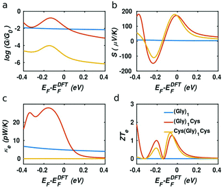
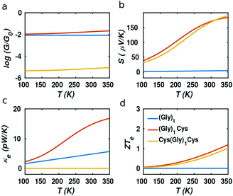
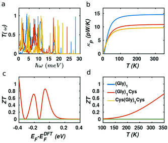
In our case, the high slopes of the transmission curves around Fermi energy for (Gly)nCys and Cys(Gly)nCys systems indicate that oligoglycines might be promising candidates for thermoelectric energy-harvesting materials. Fig. 4 shows the thermoelectric properties of (Gly)1, (Gly)1Cys and Cys(Gly)1Cys molecules containing a single glycine group (see ESI† for other series). In a large energy window within the HOMO–LUMO gap, the conductance decreases due to the increase of molecular length when one or two cysteines are added. However, near the Fermi energy, the electrical conductance of glycine with one cysteine is comparable or even higher than the one without cysteine, due to the peak caused by the sulphur anchor. For Cys(Gly)1Cys, the electrical conductance is approximately three orders of magnitude lower than the (Gly)1Cys and (Gly)1 devices. Similarly, the thermal conductance due to electrons of Cys(Gly)1Cys is much lower than those of other two structures. For glycine with cysteine(s), the Seebeck coefficients both reach to 0.2 mV K−1 at the vicinity of Fermi energy. Consequently, a higher electronic figure of merit ZTe of ∼1.5 could be obtained when oligoglycine is terminated by cysteines, as shown in Fig. 4d around −0.05 eV. In addition, the Seebeck coefficients and thermoelectric figures of merit are quite similar for the two molecules with cysteines. Fig. 5 shows the effect of temperature on the thermoelectric performance and reveals that the electronic thermoelectric figure of merit ZTe could increase further with increasing temperature.
It should be noted that the electronic figure of merit ZTe = ZTe = S2GT/κe in Fig. 4 and 5 includes the thermal conductance κe due to electrons, but excludes the thermal concuctance κp due to phonons. When phonons are included, the experimentally-measured full ZT = S2GT/(κe + κp) will certainly be lower than ZTe, as discussed in literature.24,46 Therefore, we now compute the phonon contribution κp to the thermal conductance (see Theoretical methods). Since the highest ZT occurs when κp is less than or comparable with κe, we focus on the highest conductance molecules, (Gly)1, (Gly)1Cys and Cys(Gly)1Cys, whose phonon transmissions and corresponding phononic thermal conductances are shown in Fig. 6a and b. The room-temperature thermal conductance due to phonons decreases from 14.6 pW K−1 to 10.8 pW K−1, and then to 9.7 pW K−1 as the molecular lengths increase from (Gly)1 to (Gly)1Cys and then to Cys(Gly)1Cys junctions. Their room-temperature figures of merit ZT versus Fermi energy are plotted in Fig. 6c. In contrast with the electronic figure of merit ZTe, the ZT of Cys(Gly)1Cys is reduced to nearly 0, since its phononic thermal conductance (∼9.7 pW K−1) plays a dominant role compared to the electronic part (∼0.01 pW K−1) as shown in Fig. 5c and 6b. In contrast for (Gly)1Cys, since its phononic thermal conductance (about 10.8 pW K−1) is comparable to its electronic counterpart (about 15 pW K−1), ZT is approximately reduced by only half compared with ZTe. Consequently, for (Gly)1Cys, a high ZT = 0.8 is obtained around −0.05 eV, as shown in Fig. 6c. Fig. 6d shows the variation of ZT with temperature at the DFT-estimated Fermi energy and reveals that the ZT of (Gly)1Cys increases to 0.7 when the temperature reaches 350 K.
Theoretical methods
The DFT code SIESTA47 was utilized to obtain the optimized geometry with the generalised gradient approximation (GGA) and PBE functional48 exchange and correlation. We also chose a double-ζ (DZ) for Au and double plus polarized (DZP) basis set for other elements. The resulting mean-field Hamiltonian and overlap matrices were then extracted to be used for computing the electrical properties of the devices with transport code Gollum.49 The transmission coefficient T(E) as a function of energy is calculated through the equation:| T(E) = Tr[ΓL(E)GF(E)ΓR(E)G†F(E)] | (1) |
| G = G0L0 | (2) |
 | (3) |
 | (4) |
 | (5) |
 | (6) |
The electronoic figure of merit ignores the thermal conductance κp due to phonons, whereas the figure of merit ZT experimentally is defined by ZT = S2GT/(κe + κp), which includes the thermal conductance due to both phonons and electrons in the denominator.
To calculate the thermal conductance κp due to phonons, the force constant matrix, K, is obtained by finite differences:
 | (7) |
 , where mi (mj) is the mass of atom i(j). Then the dynamical matrix is used to compute the transmission probability of phonons using Gollum transport code with eqn (1). The corresponding phononic thermal conductance is given by
 | (8) |
Conclusions
Combining density functional theory and Green's function scattering techniques, we have calculated the electrical conductance as a function of energy for (Gly)n, (Gly)nC and Cys(Gly)nCys systems. Our results show that anchors containing sulphur have significant influence on their transport properties and lead to higher β factors. In particular, we find β factors of 1.57 Å−1 and 1.22 Å−1 for (Gly)nCys and Cys(Gys)nCys respectively while β = 0.92 Å−1 for (Gly)n. Furthermore, it is also found that replacing the peptide bond with a methylene group increases the conductance of single-(Gly)3Cys molecular junctions. This demonstrates that the lone pairs of electrons in oxygen and nitrogen atoms in oligopeptide do not enhance the single-molecule conductance in comparison with fully saturated alkane chains. We find the (Gly)nCys and Cys(Gly)nCys systems show good thermoelectrical properties with high Seebeck coefficients (∼0.2 mV K−1) induced by the sulphur in cysteine. After taking both phonons and electrons contributions into account, we find the (Gly)1Cys shows good thermoelectrical properties where a high figure of merit ZT = 0.8 could be achieved at room temperature and the ZT shows an increasing trend with the rise of temperature. This high ZT implies that peptide-based SAM junctions are promising candidates for thermoelectric energy harvesting.Conflicts of interest
There are no conflicts to declare.Acknowledgements
H. S. acknowledges the Leverhulme Trust for Early Career Fellowship no. ECF-2017-186. This work was supported by EPSRC grants EP/P027156/1, EP/N03337X/1, EP/N017188/1 and the EU H2020 FET Open project 767187 “QuIET” and the EU project Bac-to-Fuel.Notes and references
- H. B. Gray and J. R. Winkler, Q. Rev. Biophys., 2003, 36, 341–372 CrossRef CAS PubMed.
- B. Giese, M. Graber and M. Cordes, Curr. Opin. Chem. Biol., 2008, 12, 755–759 CrossRef CAS PubMed.
- P. G. Falkowski, T. Fenchel and E. F. Delong, Science, 2008, 320, 1034–1039 CrossRef CAS PubMed.
- J. Juhaniewicz, J. Pawlowski and S. Sek, Isr. J. Chem., 2015, 55, 645–660 CrossRef CAS.
- S. Sek, Biopolymers, 2013, 100, 71–81 CrossRef CAS PubMed.
- N. Amdursky, ChemPlusChem, 2015, 80, 1075–1095 CrossRef CAS.
- N. Amdursky, D. Marchak, L. Sepunaru, I. Pecht, M. Sheves and D. Cahen, Adv. Mater., 2014, 26, 7142–7161 CrossRef CAS PubMed.
- Y. K. Shin, M. D. Newton and S. S. Isied, J. Am. Chem. Soc., 2003, 125, 3722–3732 CrossRef CAS PubMed.
- J. Gao, P. Müller, M. Wang, S. Eckhardt, M. Lauz, K. M. Fromm and B. Giese, Angew. Chem, Int. Ed., 2011, 50, 1926–1930 CrossRef CAS PubMed.
- M. Baghbanzadeh, C. M. Bowers, D. Rappoport, T. Zaba, M. Gonidec, M. H. Al-Sayah, P. Cyganik, A. Aspuru-Guzik and G. M. Whitesides, Angew. Chem, Int. Ed., 2015, 54, 14743–14747 CrossRef CAS PubMed.
- R. A. Malak, Z. Gao, J. F. Wishart and S. S. Isied, J. Am. Chem. Soc., 2004, 126, 13888–13889 CrossRef CAS PubMed.
- R. A. Marcus and N. Sutin, Biochim. Biophys. Acta, Rev. Bioenerg., 1985, 811, 265–322 CrossRef CAS.
- M. Magoga and C. Joachim, Phys. Rev. B: Condens. Matter Mater. Phys., 1997, 56, 4722–4729 CrossRef CAS.
- X. Xiao, B. Xu and N. Tao, J. Am. Chem. Soc., 2004, 126, 5370–5371 CrossRef CAS PubMed.
- J. M. Brisendine, S. Refaely-Abramson, Z. F. Liu, J. Cui, F. Ng, J. B. Neaton, R. L. Koder and L. Venkataraman, J. Phys. Chem. Lett., 2018, 9, 763–767 CrossRef CAS PubMed.
- E. Lörtscher, C. J. Cho, M. Mayor, M. Tschudy, C. Rettner and H. Riel, ChemPhysChem, 2011, 12, 1677–1682 CrossRef PubMed.
- V. Obersteiner, D. A. Egger and E. Zojer, J. Phys. Chem. C, 2015, 119, 21198–21208 CrossRef CAS PubMed.
- B. Kim, S. H. Choi, X. Y. Zhu and C. D. Frisbie, J. Am. Chem. Soc., 2011, 133, 19864–19877 CrossRef CAS PubMed.
- F. Chen, X. Li, J. Hihath, Z. Huang and N. Tao, J. Am. Chem. Soc., 2006, 128, 15874–15881 CrossRef CAS PubMed.
- S. Sangtarash, A. Vezzoli, H. Sadeghi, N. Ferri, H. M. O'Brien, I. Grace, L. Bouffier, S. J. Higgins, R. J. Nichols and C. J. Lambert, Nanoscale, 2018, 10, 3060–3067 RSC.
- P. Reddy and S. Jang, Science, 2007, 315, 1568–1571 CrossRef CAS PubMed.
- J. A. Malen, P. Doak, K. Baheti, T. D. Tilley, A. Majumdar and R. A. Segalman, Nano Lett., 2009, 9, 3406–3412 CrossRef CAS PubMed.
- W. B. Chang, C. K. Mai, M. Kotiuga, J. B. Neaton, G. C. Bazan and R. A. Segalman, Chem. Mater., 2014, 26, 7229–7235 CrossRef CAS.
- Q. Zhang, Y. Sun, W. Xu and D. Zhu, Adv. Mater., 2014, 26, 6829–6851 CrossRef CAS PubMed.
- H. Karamitaheri, M. Pourfath, R. Faez and H. Kosina, J. Appl. Phys., 2011, 110, 054506 CrossRef.
- V. M. Garcia-Suarez, R. Ferrads and J. Ferrer, Phys. Rev. B: Condens. Matter Mater. Phys., 2013, 88, 235417 CrossRef.
- Q. Wu, H. Sadeghi, V. M. García-Suárez, J. Ferrer and C. J. Lambert, Sci. Rep., 2017, 7, 11680 CrossRef PubMed.
- Q. Wu, H. Sadeghi and C. Lambert, Nanoscale, 2018, 10, 7575–7580 RSC.
- R. Venkatasubramanian, E. Siivola, T. Colpitts and B. O'Quinn, Nature, 2001, 413, 597–602 CrossRef CAS PubMed.
- L. Sepunaru, S. Refaely-Abramson, R. Lovrinčić, Y. Gavrilov, P. Agrawal, Y. Levy, L. Kronik, I. Pecht, M. Sheves and D. Cahen, J. Am. Chem. Soc., 2015, 137, 9617–9626 CrossRef CAS PubMed.
- H. Uji, T. Morita and S. Kimura, Phys. Chem. Chem. Phys., 2013, 15, 757–760 RSC.
- J. Juhaniewicz and S. Sek, Bioelectrochemistry, 2012, 87, 21–27 CrossRef CAS PubMed.
- X. Roy, M. L. Steigerwald and L. Venkataraman, Phys. Chem. Chem. Phys., 2012, 14, 13841–13845 RSC.
- E. Leary, H. Höbenreich, S. J. Higgins, H. Van Zalinge, W. Haiss, R. J. Nichols, C. M. Finch, I. Grace, C. J. Lambert, R. McGrath and J. Smerdon, Phys. Rev. Lett., 2009, 102, 1–4 CrossRef PubMed.
- C. Guo, X. Yu, S. Refaely-Abramson, L. Sepunaru, T. Bendikov, I. Pecht, L. Kronik, A. Vilan, M. Sheves and D. Cahen, Proc. Natl. Acad. Sci. U. S. A., 2016, 113, 10785–10790 CrossRef CAS PubMed.
- D. N. B. Tatiana, R. Prytkova and I. V. Kurnikov, Science, 2007, 315, 622–626 CrossRef PubMed.
- M. Wang, H. Wang, G. Zhang, Y. Wang, S. Sanvito and S. Hou, J. Chem. Phys., 2018, 148, 184703 CrossRef PubMed.
- Z. Xie, I. Bâldea, S. Oram, C. E. Smith and C. D. Frisbie, ACS Nano, 2017, 11, 569–578 CrossRef CAS PubMed.
- M. Baghbanzadeh, C. M. Bowers, D. Rappoport, T. Żaba, L. Yuan, K. Kang, K. C. Liao, M. Gonidec, P. Rothemund, P. Cyganik, A. Aspuru-Guzik and G. M. Whitesides, J. Am. Chem. Soc., 2017, 139, 7624–7631 CrossRef CAS PubMed.
- L. E. Scullion, E. Leary, S. J. Higgins and R. J. Nichols, J. Phys.: Condens. Matter, 2012, 24, 164211 CrossRef PubMed.
- M. G. Reuter, M. C. Hersam, T. Seideman and M. A. Ratner, Nano Lett., 2012, 12, 2243–2248 CrossRef CAS PubMed.
- C. S. S. Sangeeth, L. Jiang and C. A. Nijhuis, RSC Adv., 2018, 8, 19939–19949 RSC.
- J. P. Small, K. M. Perez and P. Kim, Phys. Rev. Lett., 2003, 91, 1–4 CrossRef PubMed.
- M. Jonson and G. D. Mahan, Phys. Rev. B: Condens. Matter Mater. Phys., 1980, 21, 4223–4229 CrossRef CAS.
- A. M. Lunde and K. Flensberg, J. Phys.: Condens. Matter, 2005, 17, 3879–3884 CrossRef CAS PubMed.
- O. Bubnova and X. Crispin, Energy Environ. Sci., 2012, 5, 9345–9362 RSC.
- J. M. Soler, E. Artacho, J. D. Gale, A. Garcìa, J. Junquera, P. Ordejòn and D. Sànchez-Portal, J. Phys.: Condens. Matter, 2002, 14, 2745–2779 CrossRef CAS.
- J. P. Perdew, K. Burke and M. Ernzerhof, Phys. Rev. Lett., 1996, 77, 3865–3868 CrossRef CAS PubMed.
- J. Ferrer, C. J. Lambert, V. M. García-Suárez, D. Z. Manrique, D. Visontai, L. Oroszlany, R. Rodríguez-Ferradás, I. Grace, S. W. D. Bailey, K. Gillemot, H. Sadeghi and L. A. Algharagholy, New J. Phys., 2014, 16, 093029 CrossRef.
Footnote |
| † Electronic supplementary information (ESI) available. See DOI: 10.1039/c8nr08878k |
| This journal is © The Royal Society of Chemistry 2019 |

