
One-step synthesis of Fe–Au core–shell magnetic-plasmonic nanoparticles driven by interface energy minimization†
Anna
Tymoczko
a,
Marius
Kamp
 b,
Christoph
Rehbock
a,
Lorenz
Kienle
b,
Elti
Cattaruzza
c,
Stephan
Barcikowski
*a and
Vincenzo
Amendola
*d
b,
Christoph
Rehbock
a,
Lorenz
Kienle
b,
Elti
Cattaruzza
c,
Stephan
Barcikowski
*a and
Vincenzo
Amendola
*d
aTechnical Chemistry I and Center for Nanointegration Duisburg-Essen (CENIDE), University Duisburg-Essen, Universitätstr. 7, 45141 Essen, Germany. E-mail: stephan.barcikowski@uni-due.de
bInstitute for Materials Science, Synthesis and Real Structure, Kiel University, Kaiserstraße 2, 24143 Kiel, Germany
cDepartment of Molecular Sciences and Nanosystems, Università Ca’ Foscari Venezia, via Torino 155/b, I-30172 Venezia-Mestre, Italy
dDepartment of Chemical Sciences, University of Padova, via Marzolo 1, I-35131 Padova, Italy. E-mail: vincenzo.amendola@unipd.it
First published on 17th July 2019
Abstract
Directing the assembly of atoms into core–shell particles generally requires elegant but sophisticated procedures. Here we show how the thermodynamic driving force to minimization of surface and interface energy can be exploited to produce colloidal Fe–Au core–shell nanoparticles in one step and with a yield approaching 99.7% in mass. This is obtained by laser ablation with nanosecond pulses of thin bimetallic films immersed in acetone. The Fe–Au core–shell nanoparticles show magnetic and plasmonic properties, and a surface available to bioconjugation and analytical assays. This laser assisted synthetic method represents a step forward in the facile preparation of core–shell nanospheres with multiple appealing functionalities.
New conceptsCore–shell nanoparticles always fascinated scientists because of their symmetric architecture, which allows the combination of different functionalities simultaneously in the same nanomaterial. However, their unique magnetic, optical, electronic and chemical properties come at the price of a difficult synthesis, usually requiring elegant yet sophisticated procedures. We report for the first time the laser synthesis of colloidal Fe–Au core–shell magnetic-plasmonic nanoparticles, with yield approaching 99.7% in mass. The procedure requires little effort and takes advantage of thermodynamic driving forces to energy minimization at the nano-interfaces, giving nanospheres with a gold shell which covers and protects the metal iron core. The key for this unprecedented result is in the understanding of multiple aspects related to the laser synthesis approach: the thermodynamic landscape which drives to the organization of different elements into core–shell nanostructures; the use of laser pulses with appropriate duration (nanoseconds); the use of a target with appropriate structure and composition (alloy thin film on glass); the use of the organic solvent with suitable characteristics (acetone). These findings illuminate how the elemental composition and synthesis conditions determine the architecture of multicomponent nanoparticles, thus providing new horizons for the large-scale realization of core–shell nanostructures for catalysis, nanomedicine, sensing, data-storage and electronics. |
One of the main challenges in nanochemistry is represented by the control of atomic assembly into bimetallic heterogeneous nanocrystals with complex structure, such as core–shell (CS) nanoparticles (NPs).1,2 CS are of particular applicative interest because they allow the combination of different properties simultaneously in the same nanomaterial,3–5 or the construction of new structures with appealing functions.6 CS NPs are especially desirable for avoiding core degradation in a reactive environment, or for preventing leaching of harmful elements from the core to the surroundings.7 Besides, organic molecules are easily grafted on transition metals or oxide NPs when these are coated with a noble metal shell.8
The unique magnetic, optical, electronic and chemical properties displayed by CS NPs, in comparison to single phase NPs, come at the price of a more difficult synthesis.1 To date, CS nanocrystals have been obtained with extraordinary precision in the composition, size and morphology through elegant procedures,8–10 especially based on stepwise seed-mediated growth in solution.11 However, these examples often require multiple or complex steps, involving toxic or pollutant compounds, which can introduce impurities due to the many solutions and reagents involved, or require surface capping agents that limit surface availability of CS NPs.11,12
An alternative approach to achieve bimetallic crystals with the CS morphology relies on element segregation from a supersaturated solution, because of the minimization of surface and interface energy. In conditions close to thermodynamic equilibrium, this is possible when the CS structure is energetically favored compared to, either the mixed element (e.g. alloy) state in case of miscible elements, or to the segregated heterostructure in case of two immiscible components.12 The transition from a state where elements are homogeneously distributed, like a solid solution (SS), to a system where elements are segregated, like a CS, requires atomic diffusion,1,13 which is typically achieved by physical processes such as heating of thin films and consequent solid-state dewetting,12 or by laser ablation of bulk alloys in liquid environment.14,15 However, in solid state dewetting, CS NPs are obtained on a solid substrate and can be collected only by stripping procedures,12 unless irreversibly embedded in a solid matrix.7 This greatly limits the general exploitability of CS NPs such as surface conjugation with functional molecules.
In particular, element segregation from a supersaturated solution was demonstrated for Fe–Au CS, that possess intriguing magnetic and plasmonic properties valuable for applications in data storage,12 magneto-optics,8 catalysis,16 sensing,17 and biomedical fields.18 Notably, Fe–Au CS are rarely achieved in liquid environment because of the easy oxidation of metallic Fe into iron oxides with lower magnetization and non-metallic band structure.1,12 In case of laser ablation in liquid, Fe–Au NPs are obtained as a colloid, but yet with low CS yield compared to other synthetic methods, due to the production of an unavoidable fraction of SS alloy NPs.14 Recently, laser melting in liquid (LML) was also applied to the generation of CS submicron spheres by irradiation of a mixture of gold and iron oxide NPs.19 Although LML has high potential in the control of particle polydispersity,20 in case of the Fe–Au CS the procedure was limited to a size range of several hundreds of nm and to iron oxide cores. Consequently, it is of great interest to obtain CS NPs by a simple, scalable and possibly green approach.
Here we show that laser ablation synthesis in solution (LASiS) allows the production of colloidal CS NPs in one step, and without addition of toxic, pollutant or expensive chemicals, simply starting from an equimolar Au–Fe alloy thin film supported on a soda-lime glass slide. Although LASiS is usually performed with bulk targets, the use of thin films can provide several advantages for laser ablation synthesis of bimetallic nanocrystals. Due to constant progress of Physical Vapour Deposition (PVD) techniques, in terms of quality and deposition rate, as required to meet the increasing demand of the industry, the surface area that can be deposited by a commercial PVD apparatus is usually 2 m2 at a deposition rate of 10 nm per minute.21,22 Besides, the focal distance of the laser beam does not require continuous adjustment during LASiS with thin film targets, contrary to what is required by bulk targets due to their consumption.23
Here, following the typical LASiS procedure, the metallic film was immersed in acetone, and 1064 nm (6 ns) laser pulses at 22.6 mJ per pulse (3.1 J cm−2) were used to transform the solid material into a colloidal solution of Fe–Au NPs (Fig. 1A). Acetone was selected as the most favorable liquid environment for the formation of Fe–Au CS NPs, according to our previous reports.15,24,25 Besides, the colloids obtained in acetone exhibited an excellent stability for several days, with only a slow tendency to sedimentation over several weeks (see ESI† for further details). In the second part of this study, the results are compared to complementary experiments conducted in the same liquid environment and with the same wavelength of 1064 nm, but with 10 ps pulses at 0.08 mJ per pulse (4 J cm−2).
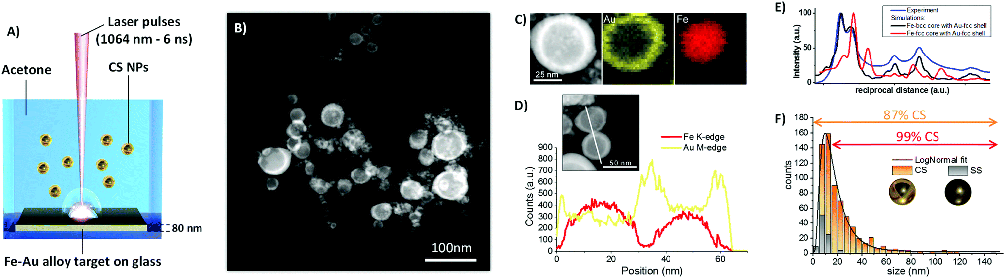 | ||
| Fig. 1 (A) Sketch of the synthetic approach based on laser ablation in liquid: laser pulses are focused on a Fe–Au alloy thin film supported on soda-lime glass and dipped in pure acetone, and NPs resulting from metal film ablation are collected as a colloid. (B) Representative Z-contrast STEM image of NPs, showing core–shell structure. (C) Bidimensional EDXS elemental maps of a representative CS NP, with Au shell in yellow (M-edge) and Fe core in red (K-edge). (D) EDXS elemental line scan analysis on a couple of CS NPs further demonstrates Fe segregation in the core (red line) and formation of the Au shell (yellow line). (E) Rotational average intensity profiles of the experiment (blue line) and the simulations for a CS NP with Au fcc shell and Fe-bcc (black line) or Fe-fcc (red line) core. The presence of Fe-fcc can be excluded by comparing the simulated diffraction intensities, overall indicating that the SAED pattern is compatible with a nanostructure containing Au-fcc and Fe-bcc. (F) The size histogram of NPs is well fitted with a LogNormal function (black line), and is composed by 87% of CS NPs and 13% of SS NPs. The fraction of CS is 99% in the size range above 15 nm. | ||
The colloid obtained by ns LASiS of the equimolar Fe–Au film in acetone was analyzed by scanning transmission electron microscopy (STEM) with a high-angle annular dark field (HAADF) detector (Fig. 1B) to investigate element distribution in the NPs by Z-contrast imaging. The Fe–Au system is favorable for the investigation of CS owing to the large difference between the atomic numbers of the two constituting elements.26 From the dark-core/bright-shell NPs layout observed from Z-contrast STEM images, it is immediately evident that the sample is composed of CS NPs where the low Z element segregated in the core and the high Z element accumulated in the shell. In rare cases, multiple cores are embedded in the same shell. The CS morphology is robust enough to remain stable in the liquid as well as after deposition on the TEM grid, without the need for a protecting layer as in other reports.7 The chemical composition of the NPs was analyzed by STEM with energy dispersive X-ray spectroscopy (EDXS) and resulted to be Fe 50 ± 5 at% and Au 50 ± 5 at%, i.e. unchanged compared to the alloy target composition. EDXS unambiguously identified the distribution of Fe and Au atoms within individual CS (Fig. 1C). The EDXS line scan on a couple of CS NPs (Fig. 1D) further substantiated element segregation into the CS architecture.
Although the reflections of body centered cubic (bcc) Fe and face centered cubic (fcc) Au overlap, the selected area electron diffraction (SAED) pattern taken from CS NPs (Fig. S2 in ESI†) shows that the lattice spacing of the respective phases agree with those expected for bcc Fe and fcc Au. Besides, the comparison of the SAED pattern with simulated patterns reported in Fig. 1E allows to exclude the presence of fcc Fe phases. Joined with the CS structure evidenced by the Z-contrast images and EDXS analysis, this allows the conclusion that the CS NPs should be two components with different crystal structure Fe-bcc (core) and Au-fcc (shell). Besides, the optical absorption spectrum of the CS colloid (Fig. S3, ESI†) exhibits an absorption edge in agreement with previous reports about LASiS of CS Fe–Au NPs in acetone.15
The size distribution measured by TEM (Fig. 1F) has the well-known LogNormal structure expected with LASiS, whose origin has been recently explained by molecular dynamics simulations of the ablation process.27 From a detailed analysis of STEM images, it is found that a minority of homogeneous solid solution (SS) NPs exists, and that this population is limited to relatively small sizes below 15 nm. Overall, in number-weighted particle size characterization, the fraction of CS accounts to the 87% of total, that reaches a remarkable value of 99% for sizes above 15 nm. It is worth to emphasize that a conservative approach was adopted for these statistics, because all NPs with size below 5 nm were counted as SS, due to the difficulty of a precise discrimination between the two morphologies in this size range from Z-contrast STEM images. However, for those applications where the surface is the reference parameter, such as catalysis28 or realization of smart self-assembled plasmonic nanosystems coated with functional molecules,6,29 the CS NPs account for the 99% of the total available surface. The overwhelming weight of the CS population becomes nearly unity (99.7%) when the volume-weighted distribution is considered. Despite the unavoidable fraction of small SS NPs, these values point to laser ablation in liquid as a highly efficient route to the generation of CS NPs relevant for surface or mass-weighted applications such as in magnetism, plasmonics and nanomedicine.
The Fe–Au CS NPs show a ready response to the external magnetic field, and can be easily aligned on a substrate such as a glass microscope slide by approaching a permanent magnet (see Fig. 2A). This is relevant for the realization of transparent coatings with improved conductivity.30 Besides, given the presence of a plasmonic gold shell, these nanoparticles can be conjugated with thiolated molecules, purified by magnetic attraction, and exploited for surface enhanced Raman scattering (SERS) detection of compounds adsorbed on their surface, as demonstrated with an aromatic thiol (nitrothiophenol, Fig. 2B). Effective surface functionalization is the key to improve sample monodispersity after LASiS, that typically requires the addition of stabilizing ligands after the synthesis, followed by post-synthesis selective centrifugation approaches,31 although this procedure is sometimes difficult in case of ferromagnetic NPs.
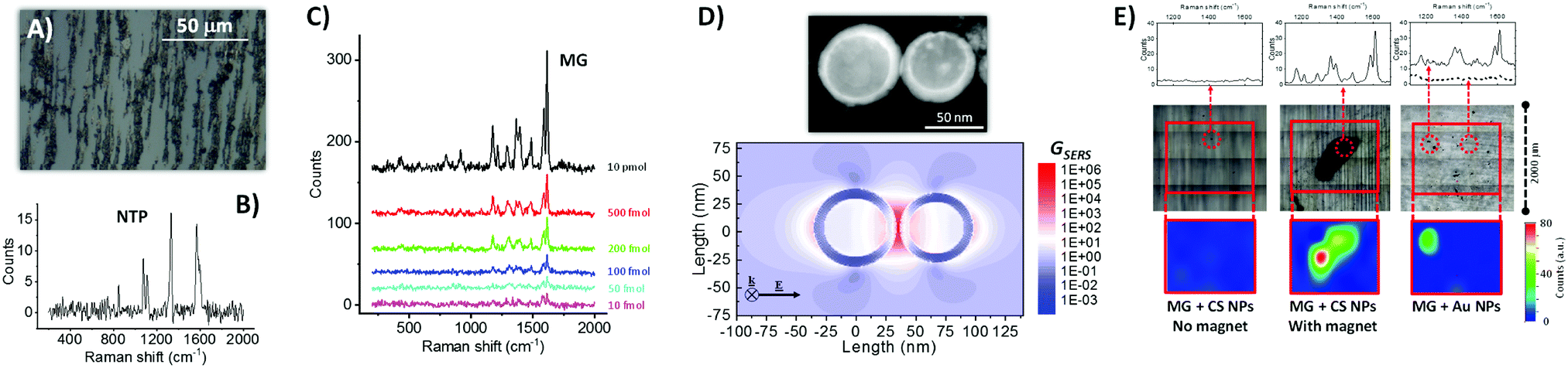 | ||
| Fig. 2 (A) Optical microscope image of Fe–Au NPs dried on a microscope glass slide in the presence of an external magnetic field, which provoked NPs alignment along the field direction because of the magnetic properties of the Fe cores. (B) Raman spectrum (532 nm excitation) of Fe–Au NPs coated with nitrothiophenol (NTP), showing all the peaks characteristics of the ligand. (C) Raman spectra of malachite green (MG) drop casted on Fe–Au NPs at different concentrations, allowing detection of the analyte down to only 10 fmol of compound added on the substrate. (D) Bidimensional map of the SERS enhancement factor (GSERS) for 532 nm excitation, calculated for a dimer of CS NPs like that shown in the STEM figure above. The result indicates that the Raman signal can be enhanced of up to 106 times at the junction between CS NPs (electromagnetic hot spot), thus confirming the plasmonic properties of the Au shell in CS NPs. (E) Comparison of Raman spectra in selected points (upper part), substrate morphology after liquid evaporation (central part), and bidimensional Raman intensity map at 1615 cm−1 (lower part) for three cases: CS NPs mixed with MG and dried on glass without a permanent magnet (left); CS NPs mixed with MG and dried on glass with a permanent magnet below the substrate (center, a black deposit of CS NPs is visible); commercial 50 nm Au NPs mixed with MG and dried on glass (right). For experimental details see ESI.† | ||
The ability of the CS NPs to act as nanoantennas was demonstrated further by SERS detection of a benchmark Raman reporter such as malachite green (4-[(4-dimethylaminophenyl)phenyl-methyl]-N,N-dimethylaniline), even at a concentration as low as 10−8 M, equivalent to 10 fmol of analyte added (Fig. 2C). These values are comparable to those typically achieved with magnetic-plasmonic nanosystems, which spans from 10−6 to 10−15 M depending on analyte type, volume of solution added, excitation wavelength and acquisition time.32,33 In fact, local electromagnetic field enhancement of up to a factor of 30 was estimated at a wavelength of 532 nm by numerical calculations on a representative dimer of coupled Fe–Au CS NPs, which corresponds to a SERS enhancement factor of 106 at the electromagnetic hot spot between the two NPs (Fig. 2D). Local field enhancement is known to scale with the volume of the NPs,34 and it is therefore very favorable in the present CS NPs because of their size in the range of tens of nanometers. For this reason, the calculation in Fig. 2D refers to a dimer of CS NPs with a relatively large size, compared to the TEM measured size distribution, because the strongest contribution to SERS signals comes from the tail of NPs with larger size.34,35 However, also if we consider a dimer of CS NPs with the average size (22.4 nm) and shell thickness (4.4 nm) extracted from TEM analysis, a SERS enhancement factor of 106 at the electromagnetic hot spot between the two NPs is observed (see Fig. S4 in ESI†).
The synergy of magnetic and plasmonic properties can greatly facilitate the SERS experiments, in terms of time, signal intensity and amount of material used, because the CS NPs can be accumulated in a pre-determined point of the substrate prior to the analysis, by using a small permanent magnet.32,33 This is shown in Fig. 2E, where a tiny amount of either CS NPs (0.7 μg, 10 μg mL−1) or a SERS benchmark represented by commercial Au NPs (50 nm in diameter, 1.5 μg, 22 μg mL−1) were mixed with 7.5 pmol of MG in water and drop casted on a glass substrate. Due to the stability of CS NPs, solvent evaporation without the presence of magnetic field does not leave any appreciable agglomerate that can be used for SERS analysis (left side of Fig. 2E); in fact the Raman spectra recorded on the area of deposition do not contain the spectral signature of the analyte. When the same colloid is evaporated by placing a small (2 mm in diameter) permanent magnet below the glass substrate, the CS NPs are accumulated in a single point, that can be easily identified by the naked eye and emits bright Raman signals coming from the analyte (center of Fig. 2E). Even in case of the reference Au NPs sample, the deposit is rather homogeneously distributed on the glass substrate after solvent evaporation, but some aggregates can be observed thanks to the higher concentration and lower stability of the colloid (right side of Fig. 2E). In this case, the spectral signature of MG is observed in some of the aggregates, although not in all of them, which forces the operator to a time-consuming investigation of different points until reaching those with a detectable signal. These results showing the ability to collect all the NPs in a predetermined point are promising in perspective of the application of the CS NPs for magnetic-plasmonic analytical assays.32,33 NPs accumulation is the most frequent strategy to increase the sensitivity when analyte concentration is low and the NPs are endowed with functionalities capable of binding the analyte. In this way, also the quantity of NPs can be reduced, which is desirable when the cost of the nanomaterial is high due to conjugation with expensive biomolecules (for instance custom-made antibodies or peptides).
The CS yield achieved in this study is remarkably larger than the best value reported in literature to date by LASiS (48% referring number-weighted histogram).14 Indeed, the main factors determining the equilibrium structure of bimetallic nanocrystals obtained by LASiS are still largely unknown. To better understand what drives the improved efficiency of Fe–Au alloy film conversion into NPs with CS morphology, the LASiS procedure was applied to a series of metal films with constant total thickness (Fig. 3A) where the two elements are completely segregated in a bilayer (Fe/Au/glass or Au/Fe/glass) or in a quadrilayer (Au/Fe/Au/Fe/glass, that can be considered as an intermediate case between the bilayer and the single alloy layer). Previous experiments about laser ablation of Fe–Au multilayers in ethanol and water evidenced that the two elements are mixed during the process, resulting in bimetallic NPs.25 Indeed, also in this case CS yield is lower with multilayer targets than with the alloy film (Fig. 3B), although surface- or volume-weighted CS fractions with still good yield of 90% are measured in samples originated from laser ablation of the Fe/Au and the Au/Fe/Au/Fe films. The general trend suggests that the targets with a topmost layer of Au show the lowest CS yield, while the alloy film ablation provides the largest CS yield. This is a favorable point for CS synthesis, because the production of a single homogeneous Fe–Au alloy film by various well-established large scale thin film deposition technologies is more convenient compared to multilayers.36
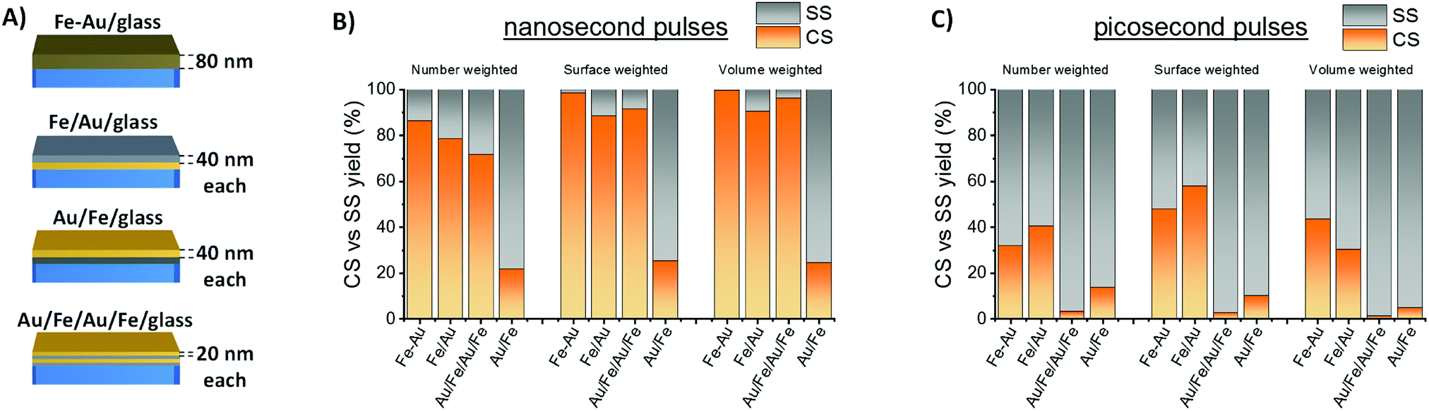 | ||
| Fig. 3 (A) Different types of Fe–Au films tested for LASiS of Fe–Au NPs in acetone. (B) CS versus SS yield measured for samples obtained by ns laser ablation of the different film types. (C) Same as (B) but for ps laser ablation. | ||
It should be noted that the best yield of CS by LASiS reported in literature to date (48% in number) was achieved with bulk Fe–Au alloy targets in acetone, using 1064 nm nanosecond laser pulses and 0.36 mJ per pulse (4 J cm−2).14 This motivated a further laser ablation experiment with a lower pulse energy of 0.08 mJ per pulse (4 J cm−2), using 10 ps pulses at 1064 nm. The resulting CS yield is markedly lower than with ns pulses (Fig. 3C), pointing to the importance of laser pulse parameters in the determination of NPs morphology.
In parallel, a difference in the size histograms of NPs is observed by changing film structure and laser pulse parameters (Fig. S5 and S6 in ESI†), with a prevalence of small particles in samples obtained with ps pulses. On the other hand, as shown in Fig. 4A, a clear correlation exists between average NPs size and CS yield, with higher CS yields found when the mean diameters of the particles are higher, which prevalently occurs in nanoparticles from ns-pulse ablation. The plot of Fig. 4A suggests that the fraction of CS NPs is negligible when the NPs average size extracted from the LogNormal size distribution is below ca. 10 nm. In addition, Fig. S6 (ESI†) shows that a high CS yield occurs when the CS fraction has a larger mean diameter than the corresponding SS fraction.
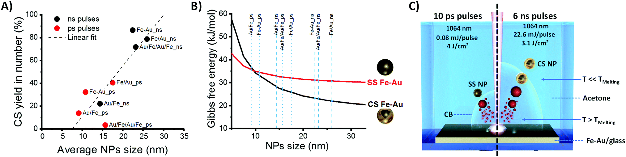 | ||
Fig. 4 (A) Plot of the average Fe–Au NPs size versus the CS yield for the samples obtained with ns (black dots) and ps (red dots) pulses from laser ablation of the four film types. Linear fit of experimental results is also reported (dashed line), indicating the absence of CS NPs for average size approaching ca. 10 nm. (B) Gibbs free energy calculated for SS (red line) and CS (black line) morphologies as a function of NPs size, for a composition of Fe![[thin space (1/6-em)]](https://www.rsc.org/images/entities/char_2009.gif) :Au 1:1. (C) Sketch of NPs formation during LASiS with the Au–Fe alloy target: with ns pulses (right), NPs form by cooling in conditions close to thermodynamic equilibrium, and with an average size exceeding the thermodynamic threshold for element segregation into CS morphology; with ps pulses (left), NPs form by quick cooling in conditions far from thermodynamic equilibrium, and with average size close to the thermodynamic threshold for element segregation into CS morphology, thus remaining in large part in a metastable SS phase. :Au 1:1. (C) Sketch of NPs formation during LASiS with the Au–Fe alloy target: with ns pulses (right), NPs form by cooling in conditions close to thermodynamic equilibrium, and with an average size exceeding the thermodynamic threshold for element segregation into CS morphology; with ps pulses (left), NPs form by quick cooling in conditions far from thermodynamic equilibrium, and with average size close to the thermodynamic threshold for element segregation into CS morphology, thus remaining in large part in a metastable SS phase. | ||
To understand the structural behavior of Fe–Au NPs, one should consider that the thermodynamic driving force for element segregation relies in the reduction of interface energy.2,13,37 It is known since the contribution of J. W. Gibbs in 1874,38 that the morphology of a given material is such that the total surface energy is minimal, and the Fe–Au systems is characterized by a large difference in surface energies between Fe and Au (1.500 J m−2 for (111) Au compared to 2.417 J m−2 for (100) Fe).26 Besides, the Fe–Au system supports several other features suitable for element segregation and formation of CS nanocrystals, which are the structural dissimilarity of body-centered cubic (bcc) iron and face-centered cubic (fcc) gold, and the large difference in lattice parameters (0.28665 nm for Fe cell and 0.40784 nm for Au cell).7,12,26,39 The different crystal structure of Fe and Au accounts also for the large miscibility gaps of the bimetallic system, with the solubility of Au in bcc Fe that is just 0.1 at% even at 500 °C.7,26
To illustrate how the balance between surface and interface energies determines the morphology of Fe–Au NPs, a thermodynamic model for interface segregation was applied (see ESI† for details). Consistently with previous findings about laser generated Fe–Au CS nanocrystals,14 the thermodynamic model clearly shows that smaller nanoparticles have a higher thermodynamic tendency to remain in a single phase (Fig. 4B), whereas above a size threshold of 10 nm for Fe(50)Au(50) nanocrystals, the thermodynamically stable phase is the CS structure. The reason is that quantities such as surface and interface energies scale with the fraction of interface atoms over the total, dominating the energetic balance for particles smaller than ca. 10 nm in diameter.37 In the SS structure, the fraction of surface Fe atoms increases with the total fraction of Fe, and Fe is characterized by the highest surface free energy contribution, therefore the size threshold for CS formation is lower for higher Fe content (see Fig. S7 in ESI†).
The results of Fig. 4B are compatible with the trend of Fig. 4A, when considering that NPs size distribution is LogNormal. In fact, the linear trend in Fig. 4A is the consequence of the progressive shift of the LogNormal size distribution to smaller sizes and the concomitant decrease of the fraction of NPs exceeding the thermodynamic threshold for CS formation.
Overall, the energetic difference between CS and SS helps understanding how surface and interfacial energies affect the geometry of Fe–Au NPs. However, the correspondence between the thermodynamic model and our experimental results is not complete, given the presence of SS NPs larger than 10 nm in several samples. In LASiS, CS formation occurs as a consequence of nanoparticle cooling in conditions close to thermodynamic equilibrium from the melted state, where element distribution is homogeneous, to the solid state, where a thermodynamic driving force to element segregation is observed in the bulk Au–Fe alloy phase diagram.14 At the nanoscale, the thermodynamic advantage in element segregation is partially balanced by the energy needed for the formation of new interfaces, that is larger for smaller nanoparticles, resulting in CS NPs only above a size threshold of ca. 10 nm for equimolar Fe–Au composition (Fig. 4B). In practice, it should be noted that thermodynamic equilibrium models are not applicable for kinetically trapped products,2,14,37 and Fe–Au alloys can exist in metastable state when atomic diffusivity is rapidly frozen.14,24,40 For instance, the cooling rate of ablated matter with ps pulses has been simulated by Zhigilei et al. to reach ∼7 × 10¹¹ K s−1.27
Here, we found that 99.7% in mass of CS nanoparticles are achieved by laser ablation with ns pulses of a 80 nm thick Fe–Au alloy film in acetone, while LASiS with ps pulses gives low CS yield. According to molecular dynamics simulations and plasma diagnostics experiments, the laser ablation mechanism is different when ns or ps pulses are used.27,41–43 In particular, with ns pulses, the laser beam partially overlaps in time with the plasma plume, and contributes to heating the plasma.42 With ps pulses, the overlap between laser beam and plasma plume only occurs for a negligible fraction of the plasma plume lifetime, that is on the timescale of hundreds of ns.42 Therefore, although the exact formation mechanism of CS NPs in LASiS deserves further investigation to be fully elucidated, we can hypothesize that, in LASiS with ns pulses and thin alloy films, the majority of nanoparticles passes from the hot liquid state to the solid state in a condition that is close to thermodynamic equilibrium, resulting in CS nanoparticles (as sketched on the right side of Fig. 4C). With ps pulses, the largest fraction of NPs forms far from thermodynamic equilibrium (as sketched on the left side of Fig. 4C). Another contributing factor is the size of NPs obtained with ns pulses, which was observed to exceed the size threshold for CS formation.
Besides, it is well known that a cavitation bubble (CB) occurs during later stages of NPs formation in LASiS, and that the CB lifetime can play a role on particle formation because, during this stage, the NPs are immersed in the CB gas phase.42,43 The CB lifetime increases with the laser pulse energy (in this case, it is 22.6 mJ for ns pulses and 0.08 mJ for ps pulses).42 Because cooling rates in the gas phase are much lower than in the liquid phase, the particles formed in a longer lasting CB have more time to reach thermodynamic equilibrium by element segregation, as required for CS formation. On the other hand, shorter CB lifetimes would mean the NPs are more quickly exposed to the cooling liquid, forming metastable structures before that element segregation occurs, as required for SS formation.
Therefore, both the differences in pulse duration and pulse energy are compatible with the experimental observation that, with ps pulses: (i) nanoparticles have a smaller average size, and (ii) the nanoparticles prevalently consist in the metastable solid solution also when the size is above the thermodynamic threshold for element segregation into the CS structure.
In case of LASiS with ns pulses, a further advantage is represented by the use of a thin film target instead of a bulk one. In fact, previous experiments of LASiS with thin Au films evidenced that the average size of nanoparticles continuously decreases by increasing the thickness of the target from <100 nm to >100 nm.44
In summary, we presented a facile synthetic strategy to produce colloidal Fe–Au magnetic plasmonic CS NPs in one step. The core–shell architecture, with Au atoms forming homogeneous layers around Fe cores, is achieved with a yield of 87% in number and 99.7% in mass by the equilibrium segregation phenomenon, because of the reduction of the total interfacial energy in the system. The procedure, based on laser ablation of an alloy thin film in acetone, is simple, green and does not introduce chemical contaminants. We further showed that core–shell NPs yield versus solid solution NPs is tunable by adjusting the thin film structure and laser pulse parameters. The potential of this method is large, considering that it exploits widely implemented thin film technologies and well-established laser ablation in liquid procedures to generate nanomaterials with a complex structure and multiple functionalities of interest for forefront applications in catalysis, nanomedicine, photonics and information technology.
Conflicts of interest
There are no conflicts to declare.Acknowledgements
A. Lucato is acknowledged for help with thin film preparation and G. Maggioni for help with Rutherford backscattering spectrometry measurements. We acknowledge financial support by the University of Padova STARS grant “4NANOMED”, the Italian Ministry of Foreign Affairs and International Cooperation (General Directorate for the Promotion of the Country System) “Great relevance project” with protocol number 0191594, DFG (BA 3580/18-1 and KI1263/15-1).References
- Y. Xia, K. D. Gilroy, H.-C. Peng and X. Xia, Angew. Chem., Int. Ed., 2017, 56, 60–95 CrossRef CAS PubMed.
- A. R. Tao, S. Habas and P. Yang, Small, 2008, 4, 310–325 CrossRef CAS.
- J. Joo, E. J. Kwon, J. Kang, M. Skalak, E. J. Anglin, A. P. Mann, E. Ruoslahti, S. N. Bhatia and M. J. Sailor, Nanoscale Horiz., 2016, 1, 407–414 RSC.
- J. Zhang, Y. Huang, X. Jin, A. Nazartchouk, M. Liu, X. Tong, Y. Jiang, L. Ni, S. Sun, Y. Sang, H. Liu, L. Razzari, F. Vetrone and J. Claverie, Nanoscale Horiz., 2019, 4, 907–917 RSC.
- D. H. Hasenöhrl, A. Saha, V. Strauss, L. Wibmer, S. Klein, D. M. Guldi and A. Hirsch, J. Mater. Chem. B, 2017, 5, 8591–8599 RSC.
- S. J. Tan, M. J. Campolongo, D. Luo and W. Cheng, Nat. Nanotechnol., 2011, 6, 268–276 CrossRef CAS PubMed.
- C. Langlois, P. Benzo, R. Arenal, M. Benoit, J. Nicolai, N. Combe, A. Ponchet and M. J. Casanove, Nano Lett., 2015, 15, 5075–5080 CrossRef CAS PubMed.
- D. Yang, X. Pang, Y. He, Y. Wang, G. Chen, W. Wang and Z. Lin, Angew. Chem., 2015, 127, 12259–12264 CrossRef.
- D. Dong, Q. Shi, D. Sikdar, Y. Zhao, Y. Liu, R. Fu, M. Premaratne and W. Cheng, Nanoscale Horiz., 2019, 4, 940–946 RSC.
- J. Park, S. Choi, A. Oh, H. Jin, J. Joo, H. Baik and K. Lee, Nanoscale Horiz., 2019, 4, 727–734 RSC.
- P.-C. Chen, J. S. Du, B. Meckes, L. Huang, Z. Xie, J. L. Hedrick, V. P. Dravid and C. A. Mirkin, J. Am. Chem. Soc., 2017, 139, 9876–9884 CrossRef CAS PubMed.
- D. Amram and E. Rabkin, ACS Nano, 2014, 8, 10687–10693 CrossRef CAS PubMed.
- J. Vernieres, S. Steinhauer, J. Zhao, P. Grammatikopoulos, R. Ferrando, K. Nordlund, F. Djurabekova and M. Sowwan, Adv. Sci., 2019, 1900447 CrossRef.
- A. Tymoczko, M. Kamp, O. Prymak, C. Rehbock, J. Jakobi, U. Schürmann, L. Kienle and S. Barcikowski, Nanoscale, 2018, 10, 16434–16437 RSC.
- P. Wagener, J. Jakobi, C. Rehbock, V. S. Chakravadhanula, C. Thede, U. Wiedwald, M. Bartsch, L. Kienle and S. Barcikowski, Sci. Rep., 2016, 6, 23352 CrossRef CAS PubMed.
- I. Vassalini, L. Borgese, M. Mariz, S. Polizzi, G. Aquilanti, P. Ghigna, A. Sartorel, V. Amendola and I. Alessandri, Angew. Chem., Int. Ed., 2017, 56, 6589–6593 CrossRef CAS PubMed.
- J. Canet-Ferrer, P. Albella, A. Ribera, J. V. Usagre and S. A. Maier, Nanoscale Horiz., 2017, 2, 205–216 RSC.
- J. Kim, S. Park, J. E. Lee, S. M. Jin, J. H. Lee, I. S. Lee, I. Yang, J.-S. Kim, S. K. Kim, M.-H. Cho and T. Hyeon, Angew. Chem., 2006, 118, 7918–7922 CrossRef.
- H. Fuse, N. Koshizaki, Y. Ishikawa, Z. Swiatkowska-Warkocka, H. Fuse, N. Koshizaki, Y. Ishikawa and Z. Swiatkowska-Warkocka, Nanomaterials, 2019, 9, 198 CrossRef CAS PubMed.
- H. Wang, A. Pyatenko, K. Kawaguchi, X. Li, Z. Swiatkowska-Warkocka and N. Koshizaki, Angew. Chem., Int. Ed., 2010, 49, 6361–6364 CrossRef CAS PubMed.
- A. Baptista, F. J. G. Silva, J. Porteiro, J. L. Míguez, G. Pinto and L. Fernandes, Procedia Manuf., 2018, 17, 746–757 CrossRef.
- U. Seyfert, U. Heisig, G. Teschner and J. Strümpfel, SVC Bull., 2015, 22–26 Search PubMed.
- S. Wirtz, A. Cunha, M. Labusch, G. Marzun, S. Barcikowski, D. Söffker, S. F. Wirtz, A. P. A. Cunha, M. Labusch, G. Marzun, S. Barcikowski and D. Söffker, Sensors, 2018, 18, 1775 CrossRef PubMed.
- V. Amendola, M. Meneghetti, O. M. Bakr, P. Riello, S. Polizzi, S. Fiameni, H. Dalaver, P. Arosio, T. Orlando, C. de Julian Fernandez, F. Pineider, C. Sangregorio and A. Lascialfari, Nanoscale, 2013, 5, 5611–5619 RSC.
- V. Amendola, S. Scaramuzza, F. Carraro and E. Cattaruzza, J. Colloid Interface Sci., 2017, 489, 18–27 CrossRef CAS PubMed.
- D. Amram, Y. Amouyal and E. Rabkin, Acta Mater., 2016, 102, 342–351 CrossRef CAS.
- C.-Y. Shih, R. Streubel, J. Heberle, A. Letzel, M. V. Shugaev, C. Wu, M. Schmidt, B. Gökce, S. Barcikowski and L. V. Zhigilei, Nanoscale, 2018, 10, 6900–6910 RSC.
- M. B. Gawande, A. Goswami, T. Asefa, H. Guo, A. V. Biradar, D.-L. Peng, R. Zboril and R. S. Varma, Chem. Soc. Rev., 2015, 44, 7540–7590 RSC.
- Z. Luo, J. Hou, L. Menin, Q. K. Ong and F. Stellacci, Angew. Chem., Int. Ed., 2017, 56, 13521–13525 CrossRef CAS PubMed.
- G. Beck, S. Barcikowski, V. S. K. Chakravadhanula, M. Comesaña-Hermo, M. Deng, M. Farle, M. Hilgendorff, J. Jakobi, J. Janek, L. Kienle, B. Mogwitz, T. Schubert and F. Stiemke, Thin Solid Films, 2015, 595, 96–107 CrossRef CAS.
- V. Amendola, S. Scaramuzza, S. Agnoli, S. Polizzi and M. Meneghetti, Nanoscale, 2014, 6, 1423–1433 RSC.
- H. Lai, F. Xu and L. Wang, J. Mater. Sci., 2018, 53, 8677–8698 CrossRef CAS.
- D. Song, R. Yang, F. Long and A. Zhu, J. Environ. Sci., 2019, 80, 14–34 CrossRef PubMed.
- V. Amendola and M. Meneghetti, Adv. Funct. Mater., 2012, 22, 353–360 CrossRef CAS.
- V. Amendola, R. Pilot, M. Frasconi, O. M. Maragò and M. A. Iatì, J. Phys.: Condens. Matter, 2017, 29, 203002 CrossRef PubMed.
- K. Seshan and D. Schepis, Handbook of Thin Film Deposition, Elsevier Ltd, 2018 Search PubMed.
- W. T. Osowiecki, X. Ye, P. Satish, K. C. Bustillo, E. L. Clark and A. P. Alivisatos, J. Am. Chem. Soc., 2018, 140, 8569–8577 CrossRef CAS PubMed.
- J. W. Gibbs, Trans. Conn. Acad. Arts Sci., 1876, 111, 108–248 Search PubMed.
- F. Calvo, N. Combe, J. Morillo and M. Benoit, J. Phys. Chem. C, 2017, 121, 4680–4691 CrossRef CAS.
- Y. P. Lee, Y. V. Kudryavtsev, V. V. Nemoshkalenko, R. Gontarz and J. Y. Rhee, Phys. Rev. B: Condens. Matter Mater. Phys., 2003, 67, 104424 CrossRef.
- C.-Y. Shih, C. Wu, M. V. Shugaev and L. V. Zhigilei, J. Colloid Interface Sci., 2017, 489, 3–17 CrossRef CAS PubMed.
- K. K. Kim, M. Roy, H. Kwon, J. K. Song and S. M. Park, J. Appl. Phys., 2015, 117, 074302 CrossRef.
- S. Barcikowski, A. Plech, K. S. Suslick and A. Vogel, MRS Bull., 2019, 44, 382–391 CrossRef.
- S. Scaramuzza, M. Zerbetto and V. Amendola, J. Phys. Chem. C, 2016, 120, 9453–9463 CrossRef CAS.
Footnote |
| † Electronic supplementary information (ESI) available: Experimental and theoretical methods; thermodynamic model; UV-vis spectra; experimental and simulated SAED patterns; additional SERS enhancement factor calculations; additional STEM images; histograms of size and CS fraction; Gibbs free energy for different compositions. See DOI: 10.1039/c9nh00332k |
| This journal is © The Royal Society of Chemistry 2019 |