
Fully integrated hierarchical double-shelled Co9S8@CNT nanostructures with unprecedented performance for Li–S batteries†
Jie
Zhou‡
,
Xiaojing
Liu‡
,
Jianbin
Zhou
 ,
Haoyu
Zhao
,
Ning
Lin
,
Linqin
Zhu
,
Yongchun
Zhu
*,
Gongming
Wang
* and
Yitai
Qian
*
,
Haoyu
Zhao
,
Ning
Lin
,
Linqin
Zhu
,
Yongchun
Zhu
*,
Gongming
Wang
* and
Yitai
Qian
*
Department of Applied Chemistry and National Laboratory for Physical Science at Microscale, University of Science & Technology of China, Hefei, Anhui 230026, P. R. China. E-mail: ychzhu@ustc.edu.cn; wanggm@ustc.edu.cn; ytqian@ustc.edu.cn
First published on 27th September 2018
Abstract
The insulating and dissoluble features of sulfur and polysulfide intermediates significantly hinder the cycling performance and coulombic efficiency of Li–S batteries. We herein design fully integrated hierarchical double-shelled Co9S8@CNT hollow nanospheres as a sulfur host, where each shell owns a tri-layer sandwich structure and six functional layers are constructed in total. Uniquely, the hierarchical structures integrate the beneficial functions of electrical conductivity, ion diffusion, polysulfide immobilization and polysulfide redox kinetics. The Co9S8@CNT/S delivers a reversible specific capacity of 1415 mA h g−1 at 0.2C, which is very close to the theoretical capacity of sulfur. Moreover, even at a high rate of 10C, an unprecedented capacity of 676.7 mA h g−1 can still be achieved, which represents the best rate capability among the ever-reported sulfur cathodes with similar sulfur content. More importantly, the Co9S8@CNT/S also displays a high coulombic efficiency of nearly 100% and an excellent cycling performance for up to 1000 cycles with a capacity fading rate of only 0.0448% per cycle. Even at the loading amount of 5.5 mg cm−2, the areal capacity can still reach 4.3 mA h cm−2. The concept to rationally integrate distinct components into fully functional units could provide valuable insights for the development of Li–S batteries and beyond.
Conceptual insightsRationally designing fully integrated hierarchical structures to resolve the polysulfide shuttling of sulfur cathodes by employing the synergistic effects between various components is always vital, but challenging due to the order of arrangements, feasibility of fabrication, interfacial contact and compatibility, as well as technically. Herein, novel carbon nanotube (CNT) wrapped double-shelled hollow Co9S8 hierarchical nanospheres (Co9S8@CNTs) with fully integrated functions are fabricated as a sulfur host, where each Co9S8 shell is sandwiched between two CNT layers. The fully integrated hierarchical structures can effectively inhibit the shuttling of polysulfides and improve the performance of Li–S batteries. This work offers a new vision for the design of fully functional sulfur cathodes. |
Introduction
Despite the fact that conventional lithium ion batteries gradually approach the physical limit of their energy densities, modern society still continuously imposes immense demand for even higher energy density batteries. The key to solving this puzzle undoubtedly lies in the development of new types of batteries.1 Lithium–sulfur (Li–S) batteries with a high theoretical energy density (2600 W h kg−1) hold great promise for the next-generation energy storage devices.2 However, the application of Li–S batteries is significantly restricted by the intrinsic properties of the electrode materials, such as the insulating nature of sulfur and lithium sulfides and the dissolution of polysulfides, which result in continuous capacity fading and low coulombic efficiency.3To this end, extensive efforts have been devoted and various strategies have been developed to solve the above-mentioned challenges.4–6 For example, encapsulating sulfur inside porous carbon hosts such as carbon spheres,7 carbon nanotubes,8 carbon nanofibers,9,10 graphene materials,11,12 and carbon hybrids13–15 has been proved to be effective in improving the performance of Li–S batteries by enhancing the electrode conductivity and employing a physical encapsulation of the dissoluble polysulfides to alleviate the “shuttle effect” to some extent.14,16 Zhang et al. reported graphene/single-walled carbon nanotube hybrids as the sulfur host, which exhibited a capacity of 650 mA h g−1 after 100 cycles at 5C.15 Since the interaction between the polar polysulfide and nonpolar carbon is weak, the introduction of polar absorbents could help to trap the polysulfides via chemical interactions.5,17–20 For instance, Liang et al. used manganese dioxide nanosheets as an efficient polysulfide mediator, achieving a capacity of ∼1300 mA h g−1 at C/20.21 Cheng et al. reported a capacity of 1252 mA h g−1 at 0.2C after 100 cycles by using porous vanadium nitride nanoribbon/graphene composites as the cathode of the Li–S battery.22 Even so, the overall reliability of Li–S batteries for practical application, especially long-term cycling performance, rate capability and safety issues, still need further improvement.
Additionally, structural engineering and reaction kinetics modulation is always crucial for electrochemical systems, including but not limited to Li–S batteries.23–29 For instance, hollow structures have been regarded as one of the ideal structures for sulfur cathodes, via accommodating the volume variation of sulfur and encapsulating the polysulfide intermediates during the charge/discharge process.30,31 On the other hand, surface modification to propel the redox reaction kinetics and shorten the diffusion time of the polysulfide intermediates is another strategy to improve the rate and cycling performance of Li–S batteries.32–36 For example, propelling polysulfide redox at sulfiphilic CoS2 promised a high initial capacity of 1368 mA h g−1 and a stable cycling performance.33 Therefore, we can foresee that rational design of a fully integrated system with distinct components and functions by employing the synergistic effects among the various components to efficiently resolve the issues of sulfur cathodes could provide new opportunities to further push the reliability of the Li–S battery towards practical applications. However, it is basically challenging to effectively couple the various components into a fully functional system, because the order of arrangements, feasibility of fabrication, interfacial contact and compatibility typically need to be seriously considered.
Herein, we design and fabricate novel carbon nanotube (CNT) wrapped double-shelled hollow Co9S8 hierarchical nanospheres (Co9S8@CNTs) with fully integrated functions (as shown in Fig. 1), where each Co9S8 shell is sandwiched between two CNT layers and a total of six functional layers with double tri-layers are uniquely created, to ideally achieve a maximized electrical conductivity, ion diffusion, polysulfide immobilization and polysulfide redox kinetics. The CNT layers function as electrically conducting layers and play interfacial contact roles, while the Co9S8 with multiple oxidation states of Co, works as a polysulfide adsorption surface and plays catalytic conversion roles. In addition, the porous and hollow features also endow the hierarchical structures with efficient ion diffusion and provide volume variation space. When used as the cathode of a Li–S battery, the Co9S8@CNTs/S deliver a high specific capacity of 1415 mA h g−1 at 0.2C, which is very close to the theoretical capacity of sulfur. Thanks to the hierarchical structural benefits, an unprecedented capacity of 676.7 mA h g−1 has been achieved at the high rate of 10C, which represents the best rate capability among the ever-reported sulfur cathodes with similar sulfur content. Moreover, it also presents an exceptional coulombic efficiency of ∼100% and an excellent cycling performance of up to 1000 cycles with a capacity fading rate of only 0.0448% per cycle. The capability to fabricate such an integrated system could offer a powerful platform to push the performance of Li–S batteries and beyond.
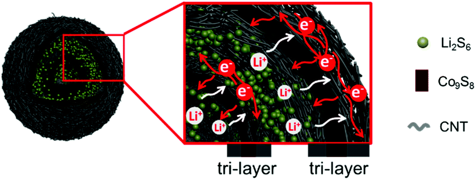 | ||
| Fig. 1 Schematic illustration of the structural advantages of the double-shelled hollow Co9S8@CNT nanospheres as a sulfur cathode, which displays a tri-layer feature in each shell and a total of six layers for the double-shelled hollow nanospheres. | ||
Results and discussion
Synthesis and characterization of Co9S8@CNTs as the sulfur host
The hierarchical Co9S8@CNTs were fabricated via a simple two-step process with Co-glycerate nanospheres, prepared by a conventional solution method, as the primary building blocks, as shown in Fig. 2a. First, the porous double-shelled hollow nanospheres were obtained by a facile sulfidation treatment of the Co-glycerate nanospheres. Then, the CNTs were grown in situ on the double-shelled hollow nanospheres to form the unique hierarchical double-shelled hollow Co9S8@CNT nanostructures (see details in experimental section). The hierarchical structures were further characterized by scanning electron microscopy (SEM) and transmission microscopy (TEM). Fig. 2b and e show that the initial Co-glycerate precursors are solid spheres with a diameter of ∼500 nm. After the sulfidation treatment, the solid nanospheres become hollow with double porous shells (Fig. 2c and f), which is attributed to the different diffusion rates of the cobalt ions and sulfur ions during the sulfidation process. The diameters of the outer shell and inner shell are about 500 nm and 200 nm, respectively. With further annealing under C2H2/Ar atmosphere, a large amount of intertwined carbon nanotubes with a diameter of less than 20 nm are uniformly anchored on the shells of the hollow nanospheres (Fig. 2d, g and Fig. S1, ESI†), because cobalt ions are typical growth catalysts for CNTs.37 The XRD analysis (Fig. S2a, ESI†) indicates that all Bragger peaks can be well indexed to the cubic Co9S8 (Fm![[3 with combining macron]](https://www.rsc.org/images/entities/char_0033_0304.gif) m), which confirms the successful preparation of a CNT wrapped double-shell Co9S8 structure. Interestingly, the TEM result reveals that the CNTs are grown on both the outer and inner shells of the double-shelled hollow nanospheres, which can be further proved by the SEM image of a broken hollow nanosphere in Fig. S2b (ESI†). This is because the porous feature can still endow the inner shells with access to the carbon sources of C2H2. Moreover, each shell is a tri-layer structure with the Co9S8 layer sandwiched between two CNT layers as shown in Fig. S2c and d (ESI†). Furthermore, in comparison to the typical point contacts between the Co9S8 hollow nanospheres, the CNTs grown on the outer shells of the Co9S8@CNTs could also enable an intimate interfacial contact between Co9S8@CNT nanospheres (Fig. 2d and g), suggesting a decreased interfacial contact resistance. Additionally, the HAADF-STEM EDS line scan profiles (Fig. S3, ESI†) also reveal the double-shelled Co9S8@CNT nanostructure, which is consistent with the TEM images. The nitrogen adsorption–desorption isotherms and the pore size distribution curves in Fig. S4 (ESI†) indicate that Co9S8@CNTs possess a surface area of 139.9 m2 g−1 and a hierarchical porous feature with micropores and mesopores. Taken together, the hierarchical hollow Co9S8@CNT nanospheres with double tri-layer shells and well improved interfacial electrical contacts have been successfully fabricated.
m), which confirms the successful preparation of a CNT wrapped double-shell Co9S8 structure. Interestingly, the TEM result reveals that the CNTs are grown on both the outer and inner shells of the double-shelled hollow nanospheres, which can be further proved by the SEM image of a broken hollow nanosphere in Fig. S2b (ESI†). This is because the porous feature can still endow the inner shells with access to the carbon sources of C2H2. Moreover, each shell is a tri-layer structure with the Co9S8 layer sandwiched between two CNT layers as shown in Fig. S2c and d (ESI†). Furthermore, in comparison to the typical point contacts between the Co9S8 hollow nanospheres, the CNTs grown on the outer shells of the Co9S8@CNTs could also enable an intimate interfacial contact between Co9S8@CNT nanospheres (Fig. 2d and g), suggesting a decreased interfacial contact resistance. Additionally, the HAADF-STEM EDS line scan profiles (Fig. S3, ESI†) also reveal the double-shelled Co9S8@CNT nanostructure, which is consistent with the TEM images. The nitrogen adsorption–desorption isotherms and the pore size distribution curves in Fig. S4 (ESI†) indicate that Co9S8@CNTs possess a surface area of 139.9 m2 g−1 and a hierarchical porous feature with micropores and mesopores. Taken together, the hierarchical hollow Co9S8@CNT nanospheres with double tri-layer shells and well improved interfacial electrical contacts have been successfully fabricated.
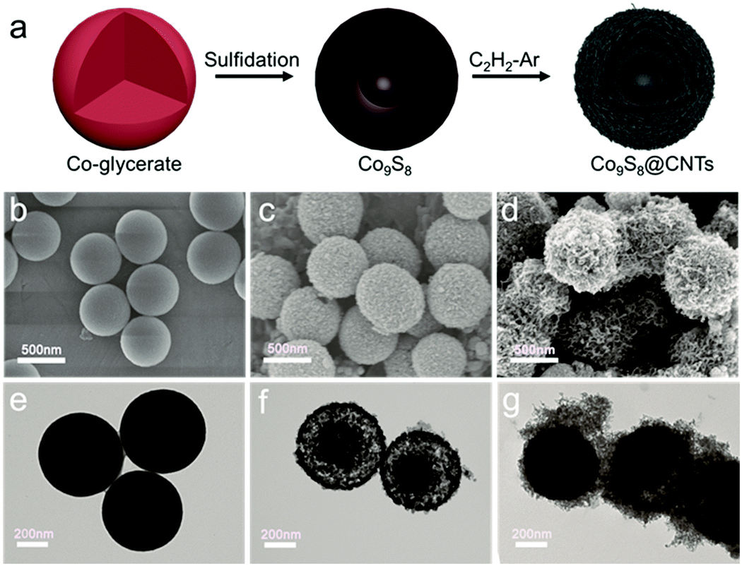 | ||
| Fig. 2 (a) Schematic illustration of the preparation process of Co9S8@CNTs. SEM images and TEM images of (b and e) the Co-glycerate nanospheres, (c and f) the double-shelled hollow Co9S8 nanospheres, and (d and g) the hierarchical double-shelled Co9S8@CNTs, respectively. | ||
Sulfur was further infiltrated in the hierarchical Co9S8@CNT nanospheres (denoted as Co9S8@CNTs/S) by a typical melt-diffusion strategy (see details in experimental section). SEM and TEM images of the Co9S8@CNTs/S (Fig. 3a and b) indicate that sulfur has been well-confined in the double-shelled structures. In addition, the high angle annular dark-field scanning TEM (HAADF-STEM) and element mapping images in Fig. 3c clearly reveal a homogeneous distribution of Co, S, and C on a single Co9S8@CNTs/S nanosphere. The XRD pattern of the Co9S8@CNTs/S shown in Fig. S5 (ESI†) exhibits the characteristic peaks of sulfur and Co9S8, further suggesting that sulfur has been successfully loaded in the Co9S8@CNTs. Besides the structural characterization, the content of sulfur and the surface chemical states of Co9S8@CNTs/S were also studied. Thermogravimetric analysis (TGA) was employed to evaluate the content of sulfur in Co9S8@CNTs/S and the weight loss in the range of 160–300 °C is attributed to the sublimation of sulfur (Fig. 3d). The weight content of sulfur in Co9S8@CNTs/S was determined to be around 68.67 wt%. The surface chemical states of Co9S8@CNTs/S were further probed using X-ray photoelectron spectroscopy (XPS). Fig. 3e shows the XPS core-level S 2p spectrum of Co9S8@CNTs/S, which can be well deconvoluted into two pairs of peaks. The peaks located at 163.5 and 164.7 eV correspond to the 2P3/2 and 2P1/2 of sulfur–sulfur bonds in elemental S, while the peaks at 161.4 and 162.5 eV are assigned to the 2P3/2 and 2P1/2 of metal–sulfur bonds in Co9S8.38,39 Additionally, the XPS core-level Co 2p of Co9S8@CNTs/S is displayed in Fig. 3f. The deconvoluted spectra suggest the existence of two kinds of chemical states of cobalt in Co9S8, which is consistent to the tetrahedral and octahedral lattice sites in Co9S8.38 The peaks located at 779.3 and 794.5 eV originate from the Co–Co bond, while the peaks at 781.6 eV and 797.1 eV are attributed to the Co–S bonds. The multiple chemical states and the polar surface of Co9S8 could enable high chemical affinity toward lithium polysulfides and possible catalytic activity for polysulfide redox conversion.40,41
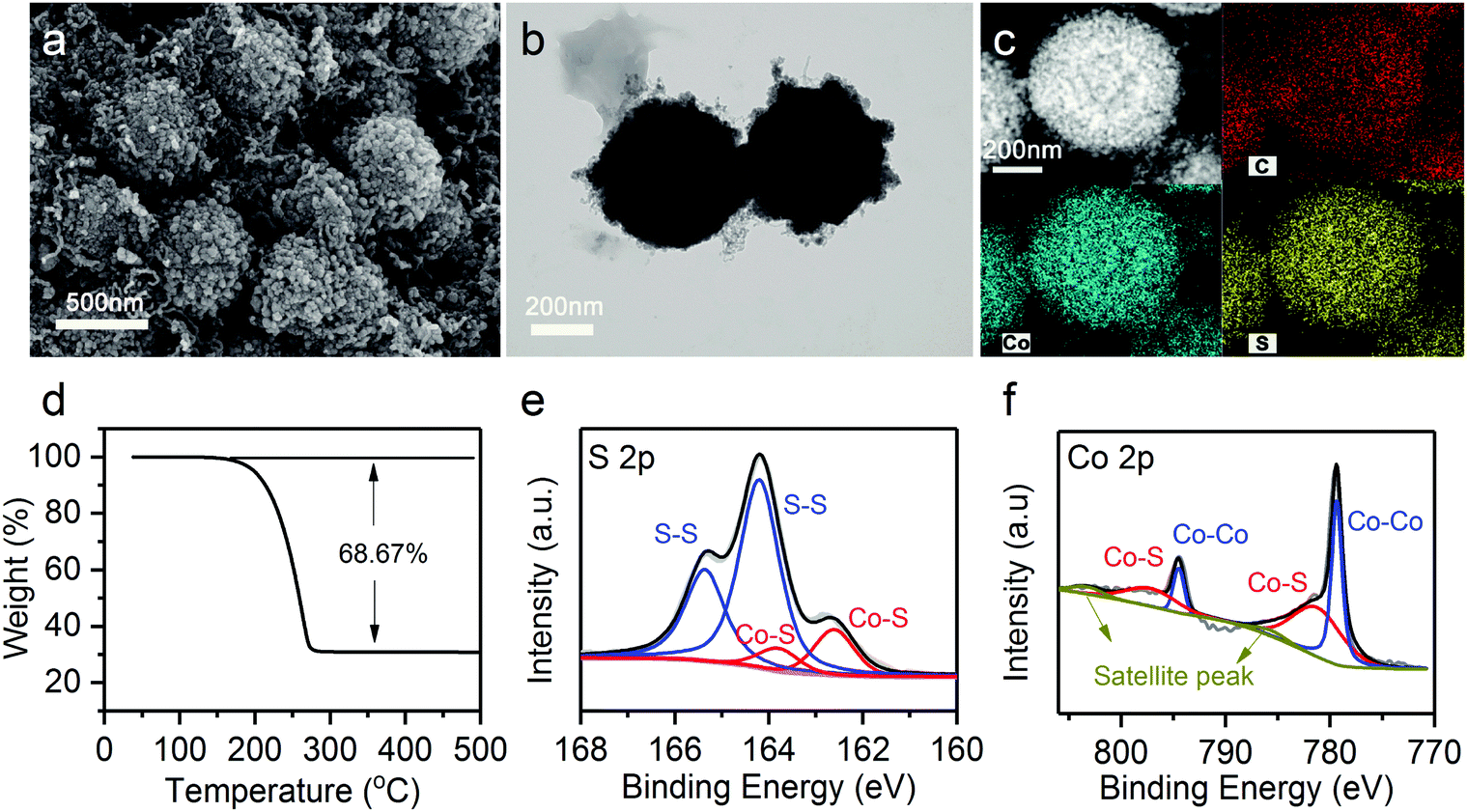 | ||
| Fig. 3 (a) SEM image, (b) TEM image, (c) HAADF-STEM and element images, and (d) TGA analysis of Co9S8@CNTs/S. (e) XPS core-level S 2p spectrum and (f) XPS core-level Co 2p spectrum of Co9S8@CNTs/S. | ||
Absorption and catalytic capability of Co9S8@CNTs for polysulfides
To study the effects of Co9S8@CNTs on the polysulfide redox kinetics, a symmetrical cell was assembled with Li2S6 as the electrolyte. Fig. 4a and Fig. S6 (ESI†) show the cyclic voltammetry (CV) curves of Co9S8@CNTs, Co9S8 and CNTs as the symmetric electrodes in the voltage window from −1.0 to 1.0 V. Without Li2S6, all the samples only exhibited typical capacitive behaviour without any obvious redox peaks (Fig. S6, ESI†). After adding Li2S6, two pairs of distinct peaks corresponding to the oxidation/reduction of polysulfides were observed in all the samples. As shown in Fig. 4a, the peaks labelled as a and b correspond to the reduction of Li2S8 to Li2S6 and finally to Li2S, while the peaks of c and d are attributed to the oxidation of Li2S to Li2S6 and finally to Li2S8.34 Interestingly, the peak positions and currents, which are the two key parameters to evaluate the redox kinetics, are quite different. Fig. 4b summarizes the peak potentials and current densities of the labelled four peaks in the CV studies (Fig. 4a). Clearly, the Co9S8@CNTs show the smallest overpotential and highest current density for the polysulfide redox reactions, indicating the superior catalytic effects of the Co9S8@CNTs on the lithiation and delithation reaction processes. It is worth noting that even at a high scan rate of 9 mV s−1, well resolved redox peaks (Fig. S7, ESI†) can still be observed for Co9S8@CNTs in the CV studies, which further proves the enhanced redox kinetics and ion diffusion properties. The optimal loading amount of Co9S8 in Co9S8@CNTs is ∼20 wt%, which has been systematically studied in Fig. S8 and S9 and the supplemental note (ESI†). Besides, the adsorption capability of Co9S8@CNTs was also evaluated. Fig. 4c shows the absorption test of CNTs, Co9S8, and Co9S8@CNTs, with Li2S6 as the adsorbate. Impressively, the electrolyte solution becomes colorless for both Co9S8 and Co9S8@CNTs, while the solution with only CNTs is still pale yellow. Moreover, the absorbance of Co9S8, CNTs and Co9S8@CNTs toward polysulfides was also verified by ex situ UV-vis spectroscopy (Fig. S10, ESI†). The absorption peaks at 300–500 nm originated from Li2S6 were significantly depressed with the addition of Co9S8 and Co9S8@CNTs, which clearly suggests that Co9S8 exhibits excellent adsorption capability for Li2S6.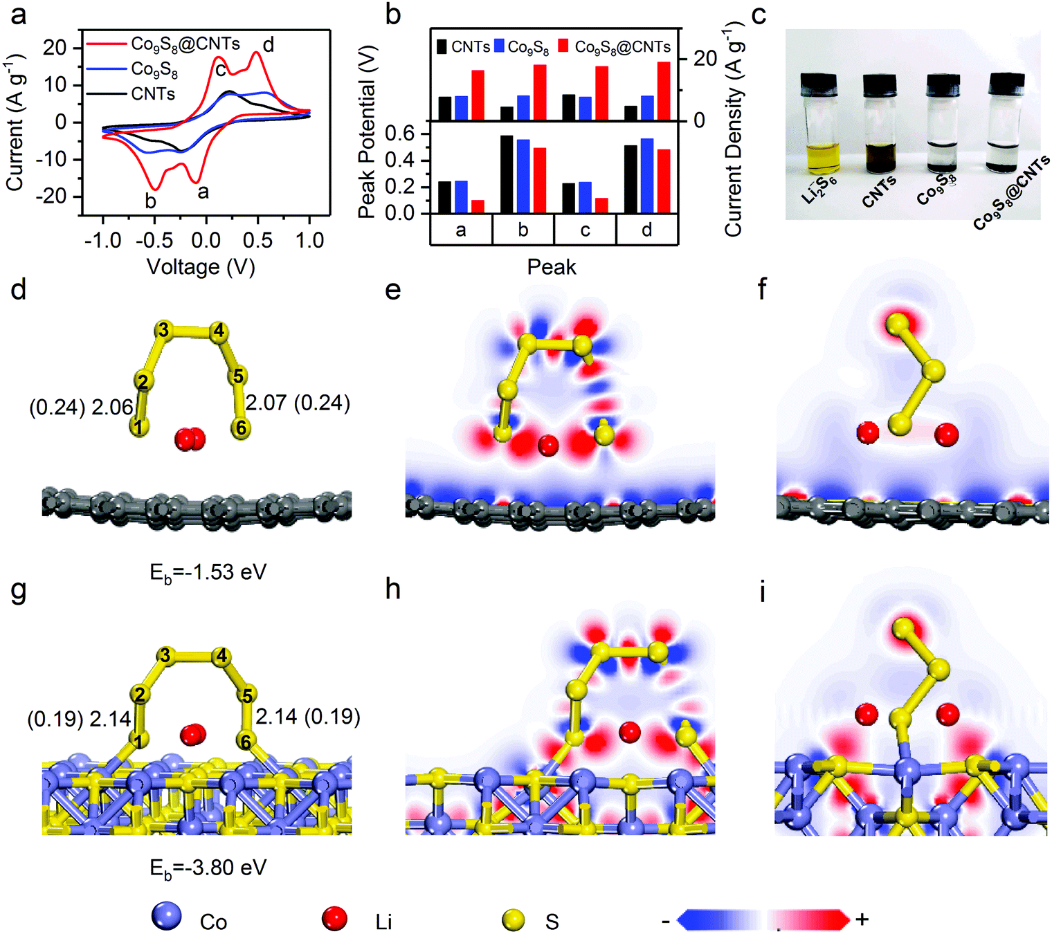 | ||
| Fig. 4 (a) Cyclic voltammograms of CNTs, Co9S8 and Co9S8@CNTs in a symmetrical cell with Li2S6 as the electrolyte. (b) The comparison of peak potentials and current density in (a). (c) The photographs of the Li2S6 solution after the absorption test. Optimized adsorption configurations with key bond lengths (bond orders) of Li2S6 on (d) graphene and (g) Co9S8, respectively. The corresponding front-view and side-view electron density difference images of Li2S6 on (e and f) graphene and (h and i) Co9S8 surfaces, respectively. | ||
The adsorption and activation capabilities toward polysulfides of Co9S8 were further revealed at the atomic and molecular scale by first-principle calculations based on density functional theory (DFT). Fig. 4d and g show the optimized adsorption configurations and energetic information of Li2S6 molecules on graphene and Co9S8. The corresponding calculated adsorption energies are −3.80 eV (Co9S8) and −1.53 eV (graphene), respectively. Apparently, Co9S8 has stronger absorbability with larger adsorption energy for Li2S6 than graphene, which can be further understood by the following electron density difference analysis (Fig. 4e, f, h, and i). The strong absorbability of Co9S8 is obviously attributed to the interfacial charge transfer between Li2S6 and Co9S8, which originated from the charge interaction between the Co sites and S sties of Co9S8 and the S and Li atoms of Li2S6 (Fig. 4h and i), respectively. Typically, adsorption is the first necessary step which is followed by redox reactions. More importantly, by comparing the structural configuration of Li2S6 before and after adsorption on Co9S8 and graphene (Fig. 4d, g and Fig. S11, ESI†), the bond lengths of S1–S2 and S5–S6 bonds for Li2S6 on Co9S8 have remarkable elongation from 2.07 Å (Li2S6) to 2.14 Å (Li2S6–Co9S8) and the corresponding bond orders decrease from 0.24 to 0.19, while there are no obvious changes for Li2S6 on grapheme. Clearly, the structural information suggests that the surface of Co9S8 could effectively activate the Li2S6 molecules for the following redox reactions, which can explain the decrease in the reaction overpotentials of Co9S8@CNTs in the CV studies (Fig. 4a and b). So far, we have demonstrated that the prepared hierarchical double-shelled hollow Co9S8@CNT structures with a total of six functional layers could fully integrate the advantages of electrical conductivity, ion diffusion, polysulfide immobilization and polysulfide redox kinetics, potentially representing an ideal cathode structure for Li–S batteries.
The electrochemical performance of Co9S8@CNTs for Li–S batteries
The potential of Co9S8@CNTs for Li–S batteries was finally evaluated using conventional 2016-type coin cells with Co9S8@CNTs/S as the cathode and Li foil as the counter electrode (see details in the Experimental Section). Meanwhile, Co9S8/S and CNTs/S with similar sulfur content were also prepared as control samples (Fig. S12 and S13, ESI†). Fig. 5a shows the CV profiles of Co9S8/S, CNTs/S and Co9S8@CNTs/S, which consistently exhibit two pairs of characteristic peaks during the charge and discharge process. At the discharge procedure, the two cathodic peaks located at 2.3 and ∼2.05 V vs. Li/Li+ originated from the gradual reduction of S8 to the long chain Li2Sx (3 < x < 8) and finally to the short chain Li2S/Li2S2. During the charge process, the two anodic peaks are ascribed to the reversible conversion of Li2S/Li2S2 to lithium polysulfides and finally to S8. Noticeably, Co9S8@CNTs/S shows negative shift in anodic peak potentials and positive shift in cathodic peak potentials compared to the Co9S8/S and CNTs/S, indicating a decreased polarization and improved redox reaction kinetics. This phenomenon is further verified by the galvanostatic charge/discharge process of the Co9S8@CNTs/S with lower polarization and higher charge storage capacity (Fig. S14, ESI†). At 0.2C, Co9S8@CNTs/S achieve a reversible specific capacity of 1415.0 mA h g−1, which is much higher than Co9S8/S (1256.0 mA h g−1) and CNTs/S (900.1 mA h g−1), and even close to the theoretical value of sulfur. The electrochemical activity of Co9S8@CNTs without loading sulfur was also investigated in Fig. S15 (ESI†). Compared with the high capacity of 1415.0 mA h g−1 of Co9S8@CNTs/S, it exhibits only a negligible capacity (20 mA h g−1), suggesting that the capacity contribution from Co9S8 is very tiny. In addition, the effect of LiNO3 is also discussed in Fig. S16 (ESI†). There is no evident difference in the cycling performance and coulombic efficiency of the Co9S8@CNTs/S with/without LiNO3 additive in the electrolyte, suggesting that Co9S8@CNTs can efficiently trap the dissolved polysulfides and suppress the shuttle effect.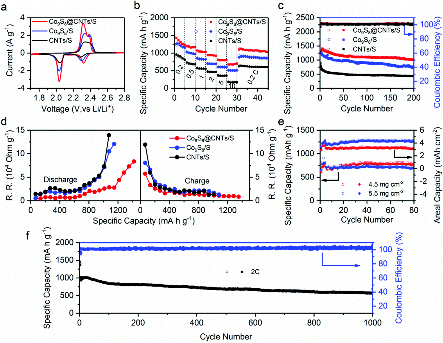 | ||
| Fig. 5 (a) Cyclic voltammograms, (b) rate performance and (c) cyclic performance at 0.2C of Co9S8@CNTs/S, Co9S8/S, and CNTs/S, respectively. (d) The corresponding reaction resistance (R.R.) obtained from the GITT voltage profiles of CNTs/S, Co9S8/S and Co9S8@CNTs/S, (e) the cyclic performance of Co9S8@CNTs/S at 0.5C with the loading amounts of 4.5 and 5.5 mg cm−2 and the corresponding areal capacities. (f) The cycling performance of Co9S8@CNTs/S at 2C over 1000 cycles. | ||
In addition, Fig. 5b displays the rate capabilities of Co9S8/S, CNTs/S and Co9S8@CNTs/S, respectively. Obviously, Co9S8@CNTs/S consistently deliver the highest specific capacities in the studied rates from 0.2C to 10C. Even at a high rate of 10C, the specific capacity of 676.7 mA h g−1 can still be achieved, suggesting the unprecedented rate capability and also representing the highest specific capacity at 10C among the ever-reported sulfur cathodes with similar sulfur content,14,42–45 as shown in Table S1 (ESI†). More importantly, Co9S8@CNTs/S also present an excellent cycling stability with a maintained capacity of 1017.5 mA h g−1 after 200 cycles at 0.2C, superior to the 766.6 mA h g−1 for Co9S8/S and 431.8 mA h g−1 for CNTs/S (Fig. 5c). The outstanding electrochemical performance of Co9S8@CNTs/S is mainly ascribed to the unique hierarchical structures, which fully integrate the functions of maximized electrical conductivity, polysulfide immobilization, ion diffusion and redox kinetics.
To further unravel the structural advantages of Co9S8@CNTs/S, electrochemical impedance spectroscopy (ESI†) and the galvanostatic intermittent titration technique (GITT) were conducted. Fig. S17b (ESI†) displays the electrochemical impedance Nyquist plots of Co9S8@CNTs/S, Co9S8/S and CNTs/S. The intercept at the real axis is related to the system ohmic resistance (RΩ) and the semicircle in the high frequency region corresponds to the interfacial charge-transfer resistance (RCT), while the diagonal line in the low frequency region is related to the ionic diffusion impedances. Clearly, Co9S8@CNTs/S with the smallest semicircle indicates the superior interfacial charge transfer resistance, which is attributed to the fully integrated structures with excellent electrical conductivity and interfacial catalytic effects. The equivalent circuit used for the simulation is presented in Fig. S17a (ESI†) and the simulated kinetic parameters are summarized in Table S2 (ESI†). In addition, Co9S8@CNTs/S with the smallest Warburg impedance (ZW), suggest the exceptional ion diffusion feature of the porous hierarchical structures, which is also estimated by the Warburg coefficient σ, and the slope of the plot between Z′ and ω−1/2 (ω = 2πf) in the low frequency region, as shown in Fig. S18 (ESI†). The Co9S8@CNTs/S with the lower σ value (σ = 3.8031 Ω s−1/2) display fast ion transmission compared to Co9S8/S (σ = 6.4892 Ω s−1/2) and CNTs/S (σ = 4.4846 Ω s−1/2). Furthermore, GITT was employed to in situ probe the reaction resistance evolution of the studied electrodes during the charge/discharge process. During the GITT measurements, the studied electrodes were first charged or discharged at 0.1C for a constant time of 30 min; then, an open circuit relaxation time of 3 h was applied to obtain an equilibrium potential. Fig. S19a (ESI†) exhibits the voltage response profiles of the Co9S8@CNTs/S, Co9S8/S and CNTs/S during the first charge/discharge cycle, respectively. The open-circuit voltages (OCVs) and closed-circuit voltages (CCVs) are also lined out in Fig. S19b–d (ESI†). The derived reaction resistances during the charge/discharge process are presented in Fig. 5d. Apparently, the Co9S8@CNTs/S consistently display the lowest reaction resistances during the charge/discharge process, revealing the well improved electrical conductivity in the hierarchical structures.
Owing to the unique hierarchical structural benefits, the Co9S8@CNTs/S can also be used as sulfur cathodes with high areal loading amounts. Fig. S20 (ESI†) shows the specific capacities and areal capacities of Co9S8@CNTs/S at 0.5C with the areal loading amounts of 2.0, 3.0 and 3.5 mg cm−2. Theoretically, increasing the areal loading amounts of sulfur is beneficial for improving the energy density of Li–S batteries. However, higher areal loading amounts typically lead to reduced sulfur utilization. Therefore, it is vital to balance sulfur utilization and areal loading of sulfur to maximize energy density. As shown in the Fig. S20a (ESI†), a capacity of 918 mA h g−1 is obtained at the rate of 0.5C with the sulfur loading of 2.0 mg cm−2 after 200 cycles, corresponding to the sulfur utilization of 54.8%. Furthermore, when the loading amounts increase to 3.0 and 3.5 mg cm−2, a capacity of 837 and 760 mA h g−1 is still retained after 200 cycles, corresponding to the sulfur utilization of 50% and 45%, respectively. The small difference in capacity and sulfur utilization with the increase of sulfur loading amounts suggests the great promise of Co9S8@CNTs as high sulfur loading electrodes with a long cycling life. Importantly, a high areal energy density of 5.5 mW h cm−2 can be obtained after 200 cycles at the loading amount of 3.5 mg cm−2. Detailed performance parameters are summarized in Table S3 (ESI†). Additionally, Fig. S21 (ESI†) displays the discharge–charge curves of Co9S8@CNTs/S with different sulfur loading amounts and summarizes the voltage polarization during the cycling process. Interestingly, the cells with the sulfur loading of 3.0 and 3.5 mg cm−2 exhibit decreased voltage polarization during cycling, which is attributed to the activation process. Further increasing the loading up to 5.5 mg cm−2, it still exhbits a promising areal capacity of 4.3 mA h cm−2 (Fig. 5e). We also tried even higher loading amounts (6.8 mg cm−2); however, the prepared electrode gets easily cracked, due to the too thick active material layer. Even so, it still delivers capacities of 642 mA h g−1 and 4.37 mA h cm−2 after 50 cycles (Fig. S22, ESI†). Besides, we further studied the influence of electrolyte on the performance of Co9S8@CNTs/S, by varying the amounts of electrolyte. Fig. S23 (ESI†) shows the electrochemical performance of Co9S8@CNTs/S with electrolyte–sulfur ratios of 15, 20 and 25 μL mg−1. With the higher electrolyte dosage of 25 μL mg−1, the electrolyte permeates the whole electrode material, which improves the effective sulfur utilization. It delivers the highest initial capacity of 1221 mA h g−1 (Fig. S23a, ESI†) and the lowest voltage polarization (Fig. S23b, ESI†). As the electrolyte decreases to 15 μL mg−1, the Co9S8@CNTs/S still delivers a high initial capacity of 1019 mA h g−1. Moreover, at the rate of 0.5C, the retained capacity after 30 cycles is 923, 870 and 853 mA h g−1 with the electrolyte amounts of 25, 20 and 15 μL mg−1, respectively. The small capacity difference suggests that Co9S8@CNTs as the host of polysulfides can well maintain the sulfur utilization with a low electrolyte–sulfur ratio, which is vital in the commercial cell. It is worth noting that the Co9S8@CNTs/S with the electrolyte ratio of 15 μL mg−1 experience a process of increasing capacity in the initial cycling at the rate of 0.5C and then the capacity gets close to those with higher electrolyte ratios. Meanwhile, the voltage polarization becomes smaller during the cycling process from the 1st cycle to 30th cycle (Fig. S23b–d, ESI†). Moreover, even with the electrolyte ratio of 10 μL mg−1 for the electrode with sulfur loading amount of 5.5 mg cm−2, it still delivers promising areal capacities, further confirming the advantages of Co9S8@CNTs/S as the sulfur cathode with low electrolyte loadings.
We finally evaluated the long-term cycling stability of Co9S8@CNTs/S for Li–S batteries. Fig. 5f displays the specific capacity retentions of Co9S8@CNTs/S at 2.0C for 1000 cycles. Even after 1000 cycles, Co9S8@CNTs/S can still maintain a high specific capacity of 560.6 mA h g−1 with a small capacity fading rate of only 0.0449% per cycle, suggesting its exceptional cycling performance. Moreover, a high coulombic efficiency close to 100% can be obtained during the long-term cycles, indicating that Co9S8@CNTs/S can effectively block the shuttle effects. Fig. S24 (ESI†) shows the optically transparent Li–S batteries, which further reveals the excellent trapping efficiency of Co9S8@CNTs toward polysulfide species. The morphology after cycling was also collected by the SEM and TEM images to probe the structural stability. As shown in Fig. S25 (ESI†), the spherical structure of Co9S8@CNTs/S can be well maintained, verifying the robustness of the hierarchical structures during cycling. All these results clearly reveal the great advantages of the fully integrated hierarchical Co9S8@CNTs/S for Li–S batteries.
Conclusions
In summary, we have rationally and successfully fabricated unique hierarchical double-shelled Co9S8@CNT hollow nanospheres, where the Co9S8 shell is sandwiched between two layers of CNTs and a total of six functional layers are uniquely created, as the host for the sulfur cathode. The hierarchical structures effectively integrate the distinct functions of electrical conductivity, ion diffusion, polysulfide immobilization and polysulfide redox kinetics, to fully employ their synergistic effects for application in Li–S batteries. Owing to their structural advantages, the Co9S8@CNTs/S exhibit a high reversible specific capacity of 1425 mA h g−1 at 0.2C, which is very close to the theoretical value of the sulfur cathode. Moreover, even at the high rate of 10C, it still displays an unprecedented specific capacity of 676.7 mA h g−1, representing the best rate performance among the ever-reported sulfur cathodes at such high rates and sulfur contents. More importantly, Co9S8@CNTs/S also present outstanding cycling performance with a capacity fading rate of only 0.0449% per cycle and maintain a specific capacity of 560.6 mA h g−1 after 1000 cycles. The successful demonstration of such a unique integrated system could provide a powerful platform to further push the performance of the Li–S batteries and beyond.Conflicts of interest
There are no conflicts to declare.Acknowledgements
We acknowledge the support of the Natural Science Fund of China (No. 11704365, GG2060190212, 21471142, 21671183, and 21671181), the National Key Research and Development Program of China (2017YFA0206703, 2016YFB0901500), the Fundamental Research Funds for the Central Universities (WK2060190074, WK2060190081, WK2060190053), the start-up funding of USTC, and the Recruitment Program of Global Experts and Anhui Provincial Natural Science Foundation (1608085MB22). We also appreciate the Photoemission Endstations (BL10B) at the National Synchrotron Radiation Laboratory for the analysis of X-ray photoelectron spectroscopy. The numerical calculations in this paper have been done on the supercomputing system at the Supercomputing Center of University of Science and Technology of China.References
- R. Fang, S. Zhao, Z. Sun, D. W. Wang, H. M. Cheng and F. Li, Adv. Mater., 2017, 29, 1606823 CrossRef PubMed.
- A. Manthiram, Y. Fu, S.-H. Chung, C. Zu and Y.-S. Su, Chem. Rev., 2014, 114, 11751–11787 CrossRef CAS PubMed.
- H. Yao, G. Zheng, P. C. Hsu, D. Kong, J. J. Cha, W. Li, Z. W. Seh, M. T. McDowell, K. Yan, Z. Liang, V. K. Narasimhan and Y. Cui, Nat. Commun., 2014, 5, 3943 CrossRef CAS PubMed.
- B. Papandrea, X. Xu, Y. Xu, C.-Y. Chen, Z. Lin, G. Wang, Y. Luo, M. Liu, Y. Huang, L. Mai and X. Duan, Nano Res., 2016, 9, 240–248 CrossRef.
- J. Zhang, Y. Shi, Y. Ding, W. Zhang and G. Yu, Nano Lett., 2016, 16, 7276–7281 CrossRef CAS PubMed.
- Y. Zhong, X. Xia, S. Deng, J. Zhan, R. Fang, Y. Xia, X. Wang, Q. Zhang and J. Tu, Adv. Energy Mater., 2018, 8, 1701110 CrossRef.
- J. Song, M. L. Gordin, T. Xu, S. Chen, Z. Yu, H. Sohn, J. Lu, Y. Ren, Y. Duan and D. Wang, Angew. Chem., Int. Ed., 2015, 54, 4325–4329 CrossRef CAS PubMed.
- J. Guo, Y. Xu and C. Wang, Nano Lett., 2011, 11, 4288–4294 CrossRef CAS PubMed.
- Z. Li, J. Zhang and X. W. D. Lou, Angew. Chem., Int. Ed., 2015, 54, 12886–12890 CrossRef CAS PubMed.
- X. Song, S. Wang, Y. Bao, G. Liu, W. Sun, L.-X. Ding, H. Liu and H. Wang, J. Mater. Chem. A, 2017, 5, 6832–6839 RSC.
- L. Ji, M. Rao, H. Zheng, L. Zhang, Y. Li, W. Duan, J. Guo, E. J. Cairns and Y. Zhang, J. Am. Chem. Soc., 2011, 133, 18522–18525 CrossRef CAS PubMed.
- Z. Cheng, Z. Xiao, H. Pan, S. Wang and R. Wang, Adv. Energy Mater., 2017, 1702337 Search PubMed.
- W. G. Chong, J. Q. Huang, Z. L. Xu, X. Qin, X. Wang and J. K. Kim, Adv. Funct. Mater., 2017, 27, 1604815 CrossRef.
- Y. Liu, G. Li, J. Fu, Z. Chen and X. Peng, Angew. Chem., 2017, 129, 6272–6276 CrossRef.
- M.-Q. Zhao, X.-F. Liu, Q. Zhang, G.-L. Tian, J.-Q. Huang, W. Zhu and F. Wei, ACS Nano, 2012, 6, 10759–10769 CrossRef CAS PubMed.
- H. Pan, Z. Cheng, Z. Xiao, X. Li and R. Wang, Adv. Funct. Mater., 2017, 27, 1703936 CrossRef.
- X. Liu, J. Q. Huang, Q. Zhang and L. Mai, Adv. Mater., 2017, 29, 1601759 CrossRef PubMed.
- J. Zhou, X. Liu, L. Zhu, J. Zhou, Y. Guan, L. Chen, S. Niu, J. Cai, D. Sun, Y. Zhu, J. Du, G. Wang and Y. Qian, Joule, 2018 DOI:10.1016/j.joule.2018.08.010.
- Y. Zhong, D. Chao, S. Deng, J. Zhan, R. Fang, Y. Xia, Y. Wang, X. Wang, X. Xia and J. Tu, Adv. Funct. Mater., 2018, 28, 1706391 CrossRef.
- S. Huang, Y. Wang, J. Hu, Y. V. Lim, D. Kong, Y. Zheng, M. Ding, M. E. Pam and H. Y. Yang, ACS Nano, 2018, 12, 9504 CrossRef CAS PubMed.
- X. Liang, C. Hart, Q. Pang, A. Garsuch, T. Weiss and L. F. Nazar, Nat. Commun., 2015, 6, 5682 CrossRef PubMed.
- Z. Sun, J. Zhang, L. Yin, G. Hu, R. Fang, H. M. Cheng and F. Li, Nat. Commun., 2017, 8, 14627 CrossRef PubMed.
- L. Zhou, Z. Zhuang, H. Zhao, M. Lin, D. Zhao and L. Mai, Adv. Mater., 2017, 29, 1602914 CrossRef PubMed.
- N. Liu, Z. Lu, J. Zhao, M. T. McDowell, H.-W. Lee, W. Zhao and Y. Cui, Nat. Nanotechnol., 2014, 9, 187–192 CrossRef CAS PubMed.
- S. Deng, Y. Zhong, Y. Zeng, Y. Wang, Z. Yao, F. Yang, S. Lin, X. Wang, X. Lu, X. Xia and J. Tu, Adv. Mater., 2017, 29, 1700748 CrossRef PubMed.
- J. Pu, Z. Shen, J. Zheng, W. Wu, C. Zhu, Q. Zhou, H. Zhang and F. Pan, Nano Energy, 2017, 37, 7–14 CrossRef CAS.
- Q. Zhao, Z. Yan, C. Chen and J. Chen, Chem. Rev., 2017, 117, 10121–10211 CrossRef CAS PubMed.
- J. Zhou, Z. Jiang, S. Niu, S. Zhu, J. Zhou, Y. Zhu, J. Liang, D. Han, K. Xu and L. Zhu, Chem, 2018, 4, 372–385 CAS.
- S. Liu, X. Xia, Y. Zhong, S. Deng, Z. Yao, L. Zhang, X.-B. Cheng, X. Wang, Q. Zhang and J. Tu, Adv. Energy Mater., 2018, 8, 1702322 CrossRef.
- S. Rehman, T. Tang, Z. Ali, X. Huang and Y. Hou, Small, 2017, 13, 1700087 CrossRef PubMed.
- T. Chen, Z. Zhang, B. Cheng, R. Chen, Y. Hu, L. Ma, G. Zhu, J. Liu and Z. Jin, J. Am. Chem. Soc., 2017, 139, 12710–12715 CrossRef CAS PubMed.
- H. Al Salem, G. Babu, C. V. Rao and L. M. Arava, J. Am. Chem. Soc., 2015, 137, 11542–11545 CrossRef CAS PubMed.
- Z. Yuan, H. J. Peng, T. Z. Hou, J. Q. Huang, C. M. Chen, D. W. Wang, X. B. Cheng, F. Wei and Q. Zhang, Nano Lett., 2016, 16, 519–527 CrossRef CAS PubMed.
- H. Lin, L. Yang, X. Jiang, G. Li, T. Zhang, Q. Yao, G. W. Zheng and J. Y. Lee, Energy Environ. Sci., 2017, 10, 1476–1486 RSC.
- Q. Pang, D. Kundu, M. Cuisinier and L. F. Nazar, Nat. Commun., 2014, 5, 4759 CrossRef CAS PubMed.
- K. Xu, X. Liu, J. Liang, J. Cai, K. Zhang, Y. Lu, X. Wu, M. Zhu, Y. Liu and Y. Zhu, ACS Energy Lett., 2018, 3, 420–427 CrossRef CAS.
- J. Meng, C. Niu, L. Xu, J. Li, X. Liu, X. Wang, Y. Wu, X. Xu, W. Chen, Q. Li, Z. Zhu, D. Zhao and L. Mai, J. Am. Chem. Soc., 2017, 139, 8212–8221 CrossRef CAS PubMed.
- Q. Pang, D. Kundu and L. F. Nazar, Mater. Horiz., 2016, 3, 130–136 RSC.
- T. Zhai, X. Lu, Y. Ling, M. Yu, G. Wang, T. Liu, C. Liang, Y. Tong and Y. Li, Adv. Mater., 2014, 26, 5869–5875 CrossRef CAS PubMed.
- S. Deng, Y. Zhong, Y. Zeng, Y. Wang, X. Wang, X. Lu, X. Xia and J. Tu, Adv. Sci., 2018, 5, 1700772 CrossRef PubMed.
- J. He, Y. Chen and A. Manthiram, Energy Environ. Sci., 2018, 11, 2560–2568 RSC.
- Z. Xiao, Z. Yang, L. Zhang, H. Pan and R. Wang, ACS Nano, 2017, 11, 8488–8498 CrossRef CAS PubMed.
- D. R. Deng, F. Xue, Y. J. Jia, J. C. Ye, C. D. Bai, M. S. Zheng and Q. F. Dong, ACS Nano, 2017, 11, 6031–6039 CrossRef CAS PubMed.
- A. Y. Kim, M. K. Kim, J. Y. Kim, Y. Wen, L. Gu, V.-D. Dao, H.-S. Choi, D. Byun and J. K. Lee, Nano Res., 2017, 10, 2083–2095 CrossRef CAS.
- L. Wang, Z. Yang, H. Nie, C. Gu, W. Hua, X. Xu, X. A. Chen, Y. Chen and S. Huang, J. Mater. Chem. A, 2016, 4, 15343–15352 RSC.
Footnotes |
| † Electronic supplementary information (ESI) available: Fig. S1–S22 and Tables S1–S3. See DOI: 10.1039/c8nh00289d |
| ‡ These authors contributed equally. |
| This journal is © The Royal Society of Chemistry 2019 |