 Open Access Article
Dynamic thin film mediated slicing of boron nitride nanotubes†
Ahmed Hussein Mohammed
Al-antaki
 ab,
Warren D.
Lawrance
c and
Colin L.
Raston
 *a
*a
aFlinders Institute for Nanoscale Science and Technology, College of Science and Engineering, Flinders University, Adelaide, SA 5042, Australia. E-mail: colin.raston@flinders.edu.au
bDepartment of Chemistry, Faculty of Sciences, Kufa University, Kufa, Najaf, Iraq
cCollege of Science and Engineering, Flinders University, Adelaide, SA 5042, Australia
First published on 23rd October 2019
Abstract
A method has been developed to slice boron nitride nanotubes BNNTs under continuous flow in a vortex fluidic device (VFD), along with a method to partially purify the as received BNNT containing material. The latter involves heating the BNNTs to 600 °C followed by dispersing in a 1![[thin space (1/6-em)]](https://www.rsc.org/images/entities/char_2009.gif) :
:![[thin space (1/6-em)]](https://www.rsc.org/images/entities/char_2009.gif) 3 isopropyl alcohol (IPA) and water mixture at 100 °C. The VFD mediated slicing of the BNNTs comprises irradiating the rapidly rotating glass tube (20 mm OD) with a pulsed Nd:YAG laser. Systematically exploring the operating parameter space of the VFD established slicing of ca. 200 μm long purified BNNTs down to 340 nm to 400 nm, in ca. 53% yield, in a 1
3 isopropyl alcohol (IPA) and water mixture at 100 °C. The VFD mediated slicing of the BNNTs comprises irradiating the rapidly rotating glass tube (20 mm OD) with a pulsed Nd:YAG laser. Systematically exploring the operating parameter space of the VFD established slicing of ca. 200 μm long purified BNNTs down to 340 nm to 400 nm, in ca. 53% yield, in a 1![[thin space (1/6-em)]](https://www.rsc.org/images/entities/char_2009.gif) :
:![[thin space (1/6-em)]](https://www.rsc.org/images/entities/char_2009.gif) 1 mixture of IPA and water, in the absence of reagents/harsh chemicals, at a flow rate of 0.45 mL min−1, a concentration of 0.1 mg mL−1 BNNTs and an 8.5k rpm rotational speed, with the pulsed laser operating at 1064 nm and 250 mJ per pulse.
1 mixture of IPA and water, in the absence of reagents/harsh chemicals, at a flow rate of 0.45 mL min−1, a concentration of 0.1 mg mL−1 BNNTs and an 8.5k rpm rotational speed, with the pulsed laser operating at 1064 nm and 250 mJ per pulse.
Introduction
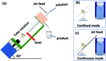
The first report of boron nitride nanotubes (BNNTs) was in 1995.1 The one dimensional (1D) tubular nanostructures (nanotubes) are related to the structure of the ubiquitous carbon nanotubes (CNTs). However, BNNTs possess different physical properties, including having a wide band gap (5.5 eV) dielectric,1,2 with photogalvanic,3 thermal conductivity and stability at high temperature (up 900 °C),4 and high neutron absorption.5 Methods for preparing BNNTs encompass substitution reactions,6 laser ablation,7 chemical vapor deposition (CVD),8,9 arc-discharge1,10 and ball-milling.11 There are three inter-related boron nitride structures, (i) straight-walled BNNT,12,13 (ii) bamboo-type BN13–15 and (iii) flower-type BN.16 The straight BNNTs have potential in a number of applications, including in boron neutron capture therapy (BNCT),5,17 hydrogen storage,16 orthopedic implants,18 biosensing19 and biomedical areas in general,2 and more.20–22 The length of BNNTs is important in a number of applications, in nanodevices,20 nanomedicines,22 sensors and composites.21 Controlling the length of BNNTs has been investigated using sonication,23,24 atomic force microscopy (AFM)25,26 and directly during chemical vapor deposition (CVD).9,27 However, these have limitations associated with damaging the BNNTs, scalability of the processing and the choice of catalyst and temperature, for the aforementioned items (i)–(iii) respectively.Single walled carbon nanotubes (SWCNTs) and multi-walled carbon nanotubes, can be sliced under high shear in a colloidal suspension in a vortex fluidic device (VFD), Fig. 1.28,29 The length of the sliced CNTs depends on the rotational speed of a borosilicate glass or quartz tube inclined at 45° relative to the horizontal position, the flow rate of liquid, concentration of the starting material and the power of the pulsed laser operating at 1064 nm.28,29 This motivated us to explore the utility of this approach to slice BNNTs in an analogous way, in the absence of additional reagents and harsh chemicals. The results are reported herein, along with a method for purifying the as received BNNTs prior to VFD processing, which we deemed necessary for simplifying the processing and any ensuing applications of the material.
The vortex fluidic device (VFD)28,30–32 has a glass or quartz tube (O.D. 20 mm, I.D. 17.5 mm and 19.5 cm in length) open at one end, and is rotated at high speed (typically up to 9k rpm) and inclined at an angle of 0 to 90° relative to the horizontal position, Fig. 1. It has two types of processing, the confined mode where a finite volume of liquid is added to the rapidly rotating tube, and the continuous flow mode.33 The former was initially used in the present study to optimise the processing before translating it into continuous flow, Fig. 1, as an often successful approach for any new application of the device.33 Overall the VFD is a versatile microfluidic platform. Beyond the above mentioned slicing of CNTs,28,29 it has been used to decorate h-BN with magnetite nanoparticles involving an in situ laser ablation of an iron rod above the dynamic thin film,34 probe the structure of self-organised systems,35 and control organic synthesis,31,36 catalysis,37 the formation of carbon dots,38 and more.30,32,39–41
Experimental
Materials
BNNTs were purchased from NanoIntegris with a purity ≥ 50% and average tube length and diameter ca. 200 μm and 5 nm, respectively, as specified by the company. Distilled IPA (isopropanol), purchased from Sigma-Aldrich, and Milli-Q water were used for all experiments.Purification of BNNTs
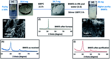
To improve the purity of BNNTs ≥50%, they were initially heated (30.4 mg of as received material) in air at 600 °C for 2.5 hours. The resulting partially oxidised material (34.7 mg) containing boric oxide,42,43 was dispersed in IPA and water (1![[thin space (1/6-em)]](https://www.rsc.org/images/entities/char_2009.gif) :
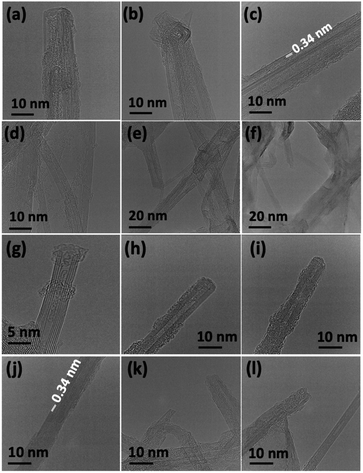
:![[thin space (1/6-em)]](https://www.rsc.org/images/entities/char_2009.gif) 3) with dissolution of the boric oxide. The material housed in a sealed vial was stirred for 3 hours at 100 °C. Centrifugation (4800 × g) for 5 min was effective in collecting the BNNTs, which were then oven dried at 70 °C. This method gave 26 mg of the material, effectively removing 14.5% by weight as impurities, Fig. 2 and 3. Other impurities possibly include material incarcerated inside the BNNTs, which become exposed once the BNNTs are sliced, Fig. 4(a–f) and S1.† The 8.7 mg of material present in the IPA and water washing contained 3.85 mg of boron, as determined using inductively coupled plasma mass spectrometry (ICPMS) (see below). However, the calculated amount of boron in the 8.7 mg, assuming it is boron oxide, is 2.7 mg. The higher percent of boron in the washings is likely to arise from removal of non-oxidised or partially oxidise boron particles.
3) with dissolution of the boric oxide. The material housed in a sealed vial was stirred for 3 hours at 100 °C. Centrifugation (4800 × g) for 5 min was effective in collecting the BNNTs, which were then oven dried at 70 °C. This method gave 26 mg of the material, effectively removing 14.5% by weight as impurities, Fig. 2 and 3. Other impurities possibly include material incarcerated inside the BNNTs, which become exposed once the BNNTs are sliced, Fig. 4(a–f) and S1.† The 8.7 mg of material present in the IPA and water washing contained 3.85 mg of boron, as determined using inductively coupled plasma mass spectrometry (ICPMS) (see below). However, the calculated amount of boron in the 8.7 mg, assuming it is boron oxide, is 2.7 mg. The higher percent of boron in the washings is likely to arise from removal of non-oxidised or partially oxidise boron particles.
Analyses
ICPMS (PerkinElmer Nex10w 350D, run in KED mode, He/low 4.7 L min−1, internal std indium) was used to determine the boron content after removing any solvent mixture (IPA and water (1![[thin space (1/6-em)]](https://www.rsc.org/images/entities/char_2009.gif) :
:![[thin space (1/6-em)]](https://www.rsc.org/images/entities/char_2009.gif) 3)) from the second step of the purification process, and collected via filtration (0.22 μm plastic filter).
3)) from the second step of the purification process, and collected via filtration (0.22 μm plastic filter).
Slicing boron nitride nanotube (BNNTs)
BNNTs (ca. 75% purity) were dispersed in IPA and water, and any slicing was investigated in the VFD by systematically varying the operating parameters of the VFD, starting with the confined mode, then continuous flow, along with the flow rate, concentration and the laser operating parameters. Optimized conditions are: 8.5k rpm rotation speed, θ 45°, flow rate 0.45 mL min−1, concentration of the BNNTs in IPA and water (1![[thin space (1/6-em)]](https://www.rsc.org/images/entities/char_2009.gif) :
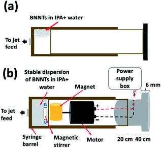
:![[thin space (1/6-em)]](https://www.rsc.org/images/entities/char_2009.gif) 1) 0.1 mg mL−1 (previously sonicated prior to processing for 30 minutes at 6 kHz to afford a dispersed solution), the pulsed Nd:YAG laser operating at 250 mJ per pulse at 1064 nm (pulse duration ∼ 5 ns). The dispersed solution prior to VFD processing is colloidally unstable, and to overcome this, the BNNTs were maintained as a suspension in solution using an in house developed magnetically stirred syringe, Fig. 5.34,38,44
1) 0.1 mg mL−1 (previously sonicated prior to processing for 30 minutes at 6 kHz to afford a dispersed solution), the pulsed Nd:YAG laser operating at 250 mJ per pulse at 1064 nm (pulse duration ∼ 5 ns). The dispersed solution prior to VFD processing is colloidally unstable, and to overcome this, the BNNTs were maintained as a suspension in solution using an in house developed magnetically stirred syringe, Fig. 5.34,38,44
Characterization
Slicing and the structure of the BNNTs were investigated using scanning electron microscopy (SEM) (SEM-Inspect FEI F50 SEM), atomic force microscopy (AFM-Nanoscope 8.10 tapping mode), XRD (Bruker D8 ADVANCE ECO, Co-Kα, λ = 1.7889 Å), ATR-FTIR PerkinElmer Frontier, EDS for HRTEM (FEI Tecnai F20 operated at 200 kV), and Raman spectroscopy (Horiba Raman with wavelength 532 nm).Results and discussion
Purification of the BNNTs
The high level of impurity in the as received BNNTs (as specified by the supplier) was addressed prior to the slicing studies. There are reports on purifying BNNTs using heating and washing with HCl45,46 and using polymers to coat the BNNTs to facilitate separation and purification.47,48 We explored a number of approaches to remove impurities from the as received material, Fig. S2–S5.† This led to the development of a simple two step method for increasing the purity of the BNNTs.The method involved heating the as received BNNTs in air at 600 °C for 2.5 hours, which effectively oxidised nitrogen and boron impurities, generating NO2 and boric oxide,42,43 with an increase in weight of the material, Fig. 2. The resulting material was white, distinctly different to the grey as received material. Thereafter the high temperature processed material was dispersed in IPA and water (volume ratio 1![[thin space (1/6-em)]](https://www.rsc.org/images/entities/char_2009.gif) :
:![[thin space (1/6-em)]](https://www.rsc.org/images/entities/char_2009.gif) 3) with the mixture stirred in a sealed vial at 100 °C for 3 hours. This effectively dissolved the boric acid, with the suspended BNNTs collected by centrifugation (4800 × g) and oven dried at 70 °C, increasing the purity of the BNNTs by 14.5%. Further attempts to increase the purity were to no avail, possibly because the impurities are incarcerated inside the BNNTs with the ends of the tubes capped, Fig. 2, 3 and S1.† XRD of the material after heating for 2.5 hours (step 1 of the processing) had two peaks at 2θ 18.4 and 32.6, which corresponds to boric oxide,42,43 and three peaks for BNNTs at 2θ 30.4, 50.6 and 64.1, Fig. 2(h and f).15,49–51 XRD for the material after the second step was devoid of peaks corresponding to boron oxide, only peaks for BNNTs, Fig. 2(i). SEM images of BNNTs before and after purification are shown in Fig. 2(e, g) and 3. EDS mapping and EDS spectra for different locations of purified BNNTs using HRTEM showed only two peaks for B and N, Fig. S6.† In addition, HRTEM for BNNTs after purification revealed the number of concentric ring layers in the tubes, Fig. S1.† ATR-FTIR for the material before and after purification established that the BNNTs are stable under the forcing conditions used in the purification process, with two peaks at 1348 cm−1 and 790 cm−1 for the B–N stretching and B–N–B bending vibrational modes respectively,51 which are vibrational modes parallel and perpendicular to the c-axis of the nanotube, Fig. 6(b).52–54
3) with the mixture stirred in a sealed vial at 100 °C for 3 hours. This effectively dissolved the boric acid, with the suspended BNNTs collected by centrifugation (4800 × g) and oven dried at 70 °C, increasing the purity of the BNNTs by 14.5%. Further attempts to increase the purity were to no avail, possibly because the impurities are incarcerated inside the BNNTs with the ends of the tubes capped, Fig. 2, 3 and S1.† XRD of the material after heating for 2.5 hours (step 1 of the processing) had two peaks at 2θ 18.4 and 32.6, which corresponds to boric oxide,42,43 and three peaks for BNNTs at 2θ 30.4, 50.6 and 64.1, Fig. 2(h and f).15,49–51 XRD for the material after the second step was devoid of peaks corresponding to boron oxide, only peaks for BNNTs, Fig. 2(i). SEM images of BNNTs before and after purification are shown in Fig. 2(e, g) and 3. EDS mapping and EDS spectra for different locations of purified BNNTs using HRTEM showed only two peaks for B and N, Fig. S6.† In addition, HRTEM for BNNTs after purification revealed the number of concentric ring layers in the tubes, Fig. S1.† ATR-FTIR for the material before and after purification established that the BNNTs are stable under the forcing conditions used in the purification process, with two peaks at 1348 cm−1 and 790 cm−1 for the B–N stretching and B–N–B bending vibrational modes respectively,51 which are vibrational modes parallel and perpendicular to the c-axis of the nanotube, Fig. 6(b).52–54
Slicing of BNNTs
A large number of experiments were undertaken to systematically explore the parameter space for the VFD in arriving at the optimal conditions. The choice of solvent considered water at different pH values, DMF (dimethylformamide), toluene, NMP (N-methyl-2-pyrrolidone) and IPA, and also mixtures of solvents, including IPA and water, DMF and water, toluene, THF and water, and toluene and water as an immiscible solvent system. This yielded sliced BNNTs but the yield of the material exiting the tube under continuous flow, except for a 1![[thin space (1/6-em)]](https://www.rsc.org/images/entities/char_2009.gif) :
:![[thin space (1/6-em)]](https://www.rsc.org/images/entities/char_2009.gif) 1 mixture of IPA and water was low. Thus, a 1
1 mixture of IPA and water was low. Thus, a 1![[thin space (1/6-em)]](https://www.rsc.org/images/entities/char_2009.gif) :
:![[thin space (1/6-em)]](https://www.rsc.org/images/entities/char_2009.gif) 1 mixture of IPA and water was deemed the optimal solvent for subsequent experiments. These experiments were carried out with the glass VFD irradiated with the 8 mm diameter beam from a pulsed Nd:YAG laser operating at 1064 nm at 250 mJ per pulse (pulse width ∼ 5 ns). The confined mode failed to produce any sliced BNNTs for the above solvents and solvent systems while irradiated in the same way.
1 mixture of IPA and water was deemed the optimal solvent for subsequent experiments. These experiments were carried out with the glass VFD irradiated with the 8 mm diameter beam from a pulsed Nd:YAG laser operating at 1064 nm at 250 mJ per pulse (pulse width ∼ 5 ns). The confined mode failed to produce any sliced BNNTs for the above solvents and solvent systems while irradiated in the same way.
The optimal rotation speed, flow rate, and concentration of BNNTs in IPA and water was then explored with different wavelength and power of the laser. All of the experiments were carried out at a tilt angle θ of 45°, as the optimal angle for many applications of the VFD.28,35,55 We found that 8.5k rpm gave the highest amount of slicing of the BNNTs (ca. 53%), with 4k rpm, 6k rpm, 7.5k rpm and 8k rpm resulting in lower conversions. The power and wavelength of the pulsed laser were also varied in tracking towards optimal slicing conditions. This included 260 mJ per pulse for the Nd:YAG second harmonic (532 nm) (a green laser) and different power for a NIR laser (1064 nm), notably 250 mJ, 400 mJ and 600 mJ, Fig. S7–S9.† Of these 250 mJ NIR laser processing in IPA and water was optimal for slicing BNNTs. The effectiveness of the NIR laser over the green laser for slicing BNNTs relates to the higher photon desorption efficiency at 1064 nm versus 532 nm.56
A flow rate of 0.45 mL min−1 was then determined as optimal, with other flow rates considered, 0.1 mL min−1, 0.3 mL min−1 and 0.7 mL min−1. Concentrations of BNNTs in IPA and water were also investigated for all of the flow rates, at 0.1 mg mL−1, 0.2 mg mL−1, and 0.3 mg mL−1, with 0.1 mg mL−1 being optimal. Thus, the optimum operating parameters for generating sliced BNNTs in a single pass through the VFD are a concentration of BNNTs of 0.1 mg mL−1, flow rate 0.45 mL min−1, rotational speed 8.5k rpm, and 250 mJ NIR laser processing, with IPA and water in a 1![[thin space (1/6-em)]](https://www.rsc.org/images/entities/char_2009.gif) :
:![[thin space (1/6-em)]](https://www.rsc.org/images/entities/char_2009.gif) 1 ratio as the processing medium.
1 ratio as the processing medium.
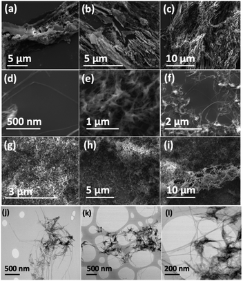
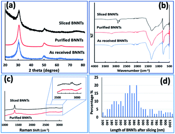
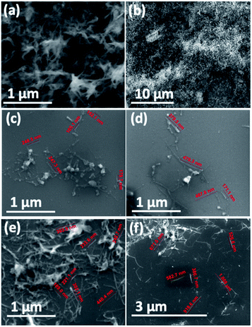
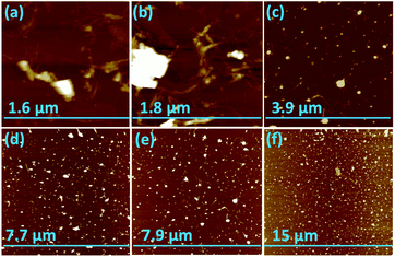
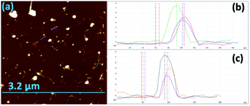
Scanning electron microscopy (SEM) was used to determine the nature of the BNNTs after processing. The images in Fig. 7(a and b) are for BNNTs after the two step purification method and before VFD processing. Images in Fig. 7(c–f) and S10† reveal the length of BNNTs after slicing in the VFD using the optimal conditions. AFM images were complementary in establishing the length of the sliced BNNTs, Fig. 8 and S11† with Fig. 6(d) presenting the length of the sliced BNNTs derived from measuring 229 tubes. In addition, AFM images were used to study the height (diameter) of six tubes, Fig. 9. HRTEM was used to explore the topology of the BNNTs before and after slicing, Fig. 4(a–f) and S1.† This shows the concentric rings and that the ends of the BNNTs after purification have their ends sealed (pre-VFD processing). However, after slicing, HRTEM shows that the ends of the BNNTs are now open, Fig. 4(g–l) and S12.† Moreover, slicing of the BNNTs in the VFD while NIR laser irradiated appears to leave the outer layer (tube) undamaged. BNNTs absorb in the NIR56 and with the bending under shear in the VFD, bond rupture is likely across the concentric rings. This is analogous to the mechanism of slicing SWCNTs, and also MWCNTs.28,29
The XRD of BNNTs before and after slicing confirm the presence of multi walled BNNTs, with the main peak at 2θ 30.4° for pre-VFD processing corresponding to the van der Waals contact distance between concentric rings of 0.34 nm.50 The same peak is present post-VFD processing (slicing) but is decreased relative to two peaks at 50.6° and 64.1°. The 30.4° peak is enhanced in the pre-processed sample due to agglomeration of the BNNTs, which have a van der Waals distance of 0.34 nm before slicing.57 Such agglomeration does not occur between the sliced tubes, Fig. 6(a). The ATR-FTIR for BNNTs after purification and after slicing has two peaks at 1348 cm−1 and 790 cm−1 for the B–N stretching and B–N–B bending vibrational modes respectively,51,58 being parallel and perpendicular to the c-axis of the nanotube, Fig. 6(b).52–54 However, the ATR-FTIR for BNNTs after slicing has other peaks at 3400 cm−1, 2920–2850 cm−1, 1100 cm−1 and 1020 cm−1 corresponding to O–H and C–H stretching, C–O stretching (secondary alcohol) and C–H bending modes respectively for IPA59,60 The Raman spectrum of BNNTs has one peak for the B–N E2g symmetry mode at 1359.5 cm−1.49,50,53,61 After processing in the VFD at the optimum conditions, the peak for the B–N E2g mode is unperturbed, Fig. 6(c),23 but now with an additional peak for included IPA at 2872.5 cm−1.62–64 This is consistent with solvent been taken up in the internal confines of the BNNTs after slicing, which are otherwise protected by endcaps. The sliced BNNTs have OH, CH, and CO peaks, arising from included IPA and water following slicing of the BNNTs which are not removed above 150 °C.
In addition, there is no evidence of dethreading the BNNTs after slicing into shorted lengths, which would be more favoured with the shorted lengths less likely to have defects which would inhibit the dethreading.
Conclusions
We have developed a simple, two step method for improving the purity of BNNTs relative to the as received material, which should in general prove useful for research based on BNNTs. It dramatically improves the ability to study their properties, in the present study their mechanical durability under high shear while being irradiated with a pulse laser. Mechanistically, the BNNTs absorb NIR radiation,56 effectively heating the material, and under shear, this is likely to result in bending and thus straining B–N bonds, leading to bond rupture and slicing of the tubes. The present study avoids the use of harsh chemical and auxiliary substances, and is without precedent. The achieved length range of the sliced tubes is 340 nm to 400 nm, which has potential in length dependent applications of BNNTs. The scalability of the processing herein was established with 30 mg of sliced BNNTs prepared in a 1![[thin space (1/6-em)]](https://www.rsc.org/images/entities/char_2009.gif) :
:![[thin space (1/6-em)]](https://www.rsc.org/images/entities/char_2009.gif) 1 mixture of IPA water using the optimum conditions, for continuous flow single pass processing in the VFD over 21 h.
1 mixture of IPA water using the optimum conditions, for continuous flow single pass processing in the VFD over 21 h.
The fluid dynamics in the VFD is inherently complex and the choice of solvent or solvent mixture depends on the application being explored and the effect of different operating parameters of the device, all of which need to be systematically explored, as in the present study, except for the tilt angle. This was fixed at 45° given that it is the optimised tilt angle for most processing in the microfluidic platform. A full understanding of the fluid flow in the VFD will facilitate the optimisation of any process, and this is a major international collaborative research project underway.
Conflicts of interest
There are no conflicts to declare.Acknowledgements
The authors gratefully acknowledge financial support from the Iraq Government, Ministry of Higher Education and Scientific Research, and the Australian Research Council and the Government of South Australia. Use of facilities in the Australian Microscopy & Microanalysis Research Facility (AMMRF) and the Australian National Fabrication Facility (ANFF) at the South Australian nodes of the AMMRF and ANFF under the National Collaborative Research Infrastructure Strategy are also acknowledged.Notes and references
- N. G. Chopra, R. J. Luyken, K. Cherrey, V. H. Crespi, M. L. Cohen, S. G. Louie and A. Zettl, Science, 1995, 269, 966–967 CrossRef CAS PubMed.
- D. Golberg, Y. Bando, Y. Huang, T. Terao, M. Mitome, C. Tang and C. Zhi, ACS Nano, 2010, 4, 2979–2993 CrossRef CAS PubMed.
- P. Král, E. J. Mele and D. Tománek, Phys. Rev. Lett., 2000, 85, 1512–1515 CrossRef PubMed.
- Y. Chen, J. Zou, S. J. Campbell and G. Le Caer, Appl. Phys. Lett., 2004, 84, 2430–2432 CrossRef CAS.
- T. H. Ferreira, M. C. Miranda, Z. Rocha, A. S. Leal, D. A. Gomes and E. M. B. Sousa, Nanomaterials, 2017, 7, 82 CrossRef PubMed.
- D. Golberg and Y. Bando, Appl. Phys. Lett., 2001, 79, 415–417 CrossRef CAS.
- T. Laude, Y. Matsui, A. Marraud and B. Jouffrey, Appl. Phys. Lett., 2000, 76, 3239–3241 CrossRef CAS.
- Y. Li, Z. Peng, E. Larios, G. Wang, J. Lin, Z. Yan, F. Ruiz-Zepeda, M. José-Yacamán and J. M. Tour, ACS Nano, 2015, 9, 532–538 CrossRef CAS PubMed.
- P. Ahmad, M. U. Khandaker, Z. R. Khan and Y. M. Amin, RSC Adv., 2015, 5, 35116–35137 RSC.
- A. Loiseau, F. Willaime, N. Demoncy, G. Hug and H. Pascard, Phys. Rev. Lett., 1996, 76, 4737–4740 CrossRef CAS PubMed.
- C. Zhuang, H. Xu, L. Li, Y. Liu, C. Ban and X. Liu, RSC Adv., 2016, 6, 113415–113423 RSC.
- S. Chatterjee, M. J. Kim, D. N. Zakharov, S. M. Kim, E. A. Stach, B. Maruyama and L. G. Sneddon, Chem. Mater., 2012, 24, 2872–2879 CrossRef CAS.
- L. H. Li, Y. Chen and A. M. Glushenkov, J. Mater. Chem., 2010, 20, 9679–9683 RSC.
- Y. Song, Y. Sun, D. H. Shin, K. N. Yun, Y.-H. Song, W. I. Milne and C. J. Lee, Appl. Phys. Lett., 2014, 104, 163102 CrossRef.
- B. Zhong, X. Huang, G. Wen, H. Yu, X. Zhang, T. Zhang and H. Bai, Nanoscale Res. Lett., 2010, 6, 36 Search PubMed.
- A. Leela Mohana Reddy, A. E. Tanur and G. C. Walker, Int. J. Hydrogen Energy, 2010, 35, 4138–4143 CrossRef.
- G. Ciofani, V. Raffa, A. Menciassi and A. Cuschieri, Nanoscale Res. Lett., 2008, 4, 113 CrossRef PubMed.
- X. Li, X. Wang, X. Jiang, M. Yamaguchi, A. Ito, Y. Bando and D. Golberg, J. Biomed. Mater. Res., Part B, 2016, 104, 323–329 CrossRef CAS PubMed.
- J. Wu and L. Yin, ACS Appl. Mater. Interfaces, 2011, 3, 4354–4362 CrossRef CAS PubMed.
- S. Kalay, Z. Yilmaz, O. Sen, M. Emanet, E. Kazanc and M. Çulha, Beilstein J. Nanotechnol., 2015, 6, 84–102 CrossRef PubMed.
- A. L. Tiano, C. Park, J. W. Lee, H. H. Luong, L. J. Gibbons, S.-H. Chu, S. Applin, P. Gnoffo, S. Lowther, H. J. Kim, P. M. Danehy, J. A. Inman, S. B. Jones, J. H. Kang, G. Sauti, S. A. Thibeault, V. Yamakov, K. E. Wise, J. Su and C. C. Fay, Proc. SPIE, 2014, 906006 Search PubMed.
- Z. Gao, C. Zhi, Y. Bando, D. Golberg and T. Serizawa, Nanobiomedicine, 2014, 1, 7 CrossRef PubMed.
- Y. Liao, Z. Chen, J. W. Connell, C. C. Fay, C. Park, J. W. Kim and Y. Lin, Adv. Funct. Mater., 2014, 24, 4497–4506 CrossRef CAS.
- C. H. Lee, D. Zhang and Y. K. Yap, J. Phys. Chem. C, 2012, 116, 1798–1804 CrossRef CAS.
- J.-H. Hsu and S.-H. Chang, Appl. Surf. Sci., 2010, 256, 1769–1773 CrossRef CAS.
- M. Zheng, X. Chen, C. Park, C. C. Fay, N. M. Pugno and C. Ke, Nanotechnology, 2013, 24, 505719 CrossRef PubMed.
- D. B. Geohegan, A. A. Puretzky, I. N. Ivanov, S. Jesse, G. Eres and J. Y. Howe, Appl. Phys. Lett., 2003, 83, 1851–1853 CrossRef CAS.
- T. M. D. Alharbi, K. Vimalanathan, W. D. Lawrance and C. L. Raston, Carbon, 2018, 140, 428–432 CrossRef CAS.
- K. Vimalanathan, J. R. Gascooke, I. Suarez-Martinez, N. A. Marks, H. Kumari, C. J. Garvey, J. L. Atwood, W. D. Lawrance and C. L. Raston, Sci. Rep., 2016, 6, 22865 CrossRef CAS PubMed.
- J. Britton, J. M. Chalker and C. L. Raston, Chem.–Eur. J., 2015, 21, 10660–10665 CrossRef CAS PubMed.
- M. N. Gandy, C. L. Raston and K. A. Stubbs, Org. Biomol. Chem., 2014, 12, 4594–4597 RSC.
- X. Chen, J. F. Dobson and C. L. Raston, Chem. Commun., 2012, 48, 3703–3705 RSC.
- J. Britton, K. A. Stubbs, G. A. Weiss and C. L. Raston, Chem.–Eur. J., 2017, 23, 13270–13278 CrossRef CAS PubMed.
- A. H. Mohammed Al-antaki, X. Luo, A. Duan, R. N. Lamb, E. Eroglu, W. Hutchison, Y.-C. Zou, J. Zou and C. L. Raston, RSC Adv., 2018, 8, 40829–40835 RSC.
- I. Alsulami, T. Alharbi, D. Harvey, C. T. Gibson and C. L. Raston, Chem. Commun., 2018, 54, 7896–7899 RSC.
- S. J. Pye, S. J. Dalgarno, J. M. Chalker and C. L. Raston, Green Chem., 2018, 20, 118–124 RSC.
- J. M. Phillips, M. Ahamed, X. Duan, R. N. Lamb, X. Qu, K. Zheng, J. Zou, J. M. Chalker and C. L. Raston, ACS Appl. Bio Mater., 2019, 2, 488–494 CrossRef CAS.
- X. Luo, A. H. M. Al-Antaki, K. Vimalanathan, J. Moffatt, K. Zheng, Y. Zou, J. Zou, X. Duan, R. N. Lamb, S. Wang, Q. Li, W. Zhang and C. L. Raston, React. Chem. Eng., 2018, 3, 164–170 RSC.
- X. Luo, P. Smith, C. L. Raston and W. Zhang, ACS Sustainable Chem. Eng., 2016, 4, 3905–3911 CrossRef CAS.
- T. Z. Yuan, C. F. Ormonde, S. T. Kudlacek, S. Kunche, J. N. Smith, W. A. Brown, K. M. Pugliese, T. J. Olsen, M. Iftikhar and C. L. Raston, ChemBioChem, 2015, 16, 393–396 CrossRef CAS PubMed.
- T. M. D. Alharbi, D. Harvey, I. K. Alsulami, N. Dehbari, X. Duan, R. N. Lamb, W. D. Lawrance and C. L. Raston, Carbon, 2018, 137, 419–424 CrossRef CAS.
- B. H. Tran, K. Tieu, S. Wan, H. Zhu, S. Cui and L. Wang, RSC Adv., 2018, 8, 28847–28860 RSC.
- Q. Yang, J. Sha, L. Wang, Y. Zou, J. Niu, C. Cui and D. Yang, Phys. E, 2005, 27, 319–324 CrossRef CAS.
- A. H. M. Al-Antaki, X. Luo, T. M. D. Alharbi, D. P. Harvey, S. Pye, J. Zou, W. Lawrance and C. L. Raston, RSC Adv., 2019, 9, 22074–22079 RSC.
- H. Chen, Y. Chen, J. Yu and J. S. Williams, Chem. Phys. Lett., 2006, 425, 315–319 CrossRef CAS.
- L. Xue-Song, C. Dian-Qiang, Z. Bo and Y. Jian-Lin, Iran. J. Chem. Chem. Eng., 2014, 33, 29–36 Search PubMed.
- J.-H. Choi, J. Kim, D. Seo and Y.-S. Seo, Mater. Res. Bull., 2013, 48, 1197–1203 CrossRef CAS.
- C. Zhi, Y. Bando, C. Tang, S. Honda, K. Sato, H. Kuwahara and D. Golberg, J. Phys. Chem. B, 2006, 110, 1525–1528 CrossRef CAS PubMed.
- V. K. Thakur, J. Yan, M.-F. Lin, C. Zhi, D. Golberg, Y. Bando, R. Sim and P. S. Lee, Polym. Chem., 2012, 3, 962–969 RSC.
- L. Wang, D. Han, J. Luo, T. Li, Z. Lin and Y. Yao, J. Phys. Chem. C, 2018, 122, 1867–1873 CrossRef CAS.
- E. Songfeng, C. Li, T. Li, R. Geng, Q. Li, W. Lu and Y. Yao, Nanotechnology, 2018, 29, 195604 CrossRef PubMed.
- E. Borowiak-Palen, T. Pichler, G. G. Fuentes, B. Bendjemil, X. Liu, A. Graff, G. Behr, R. J. Kalenczuk, M. Knupfer and J. Fink, Chem. Commun., 2003, 82–83, 10.1039/b208214d.
- S. Xu, Y. Fan, J. Luo, L. Zhang, W. Wang, B. Yao and L. An, Appl. Phys. Lett., 2007, 90, 013115 CrossRef.
- Z.-G. Chen, J. Zou, G. Liu, F. Li, Y. Wang, L. Wang, X.-L. Yuan, T. Sekiguchi, H.-M. Cheng and G. Q. Lu, ACS Nano, 2008, 2, 2183–2191 CrossRef CAS PubMed.
- X. Luo, A. H. M. Al-Antaki, T. M. D. Alharbi, W. D. Hutchison, Y.-c. Zou, J. Zou, A. Sheehan, W. Zhang and C. L. Raston, ACS Omega, 2018, 3, 11172–11178 CrossRef CAS PubMed.
- Q. Lu, Y. Hu, J. Chen, Y. Li, W. Song, S. Jin, F. Liu and L. Sheng, Talanta, 2018, 187, 106–112 CrossRef CAS PubMed.
- A. T. Matveev, K. L. Firestein, A. E. Steinman, A. M. Kovalskii, O. I. Lebedev, D. V. Shtansky and D. Golberg, Nano Res., 2015, 8, 2063–2072 CrossRef CAS.
- S.-Y. Xie, W. Wang, K. A. S. Fernando, X. Wang, Y. Lin and Y.-P. Sun, Chem. Commun., 2005, 3670–3672, 10.1039/b505330g.
- A. Shahravan, T. Desai and T. Matsoukas, Appl. Phys. Lett., 2012, 101, 251603 CrossRef.
- D. Kim, S. Nakajima, T. Sawada, M. Iwasaki, S. Kawauchi, C. Zhi, Y. Bando, D. Golberg and T. Serizawa, Chem. Commun., 2015, 51, 7104–7107 RSC.
- R. Y. Tay, H. Li, S. H. Tsang, L. Jing, D. Tan, M. Wei and E. H. T. Teo, Chem. Mater., 2015, 27, 7156–7163 CrossRef CAS.
- Z. Jin, Q. Chu, W. Xu, H. Cai, W. Ji, G. Wang, B. Lin and X. Zhang, IEEE Photonics Technol. Lett., 2018, 30, 387–390 CAS.
- L. E. Ocola, M. Costales and D. J. Gosztola, Nanotechnology, 2015, 27, 035302 CrossRef PubMed.
- Y. Mizutani, K. Kamogawa, T. Kitagawa, A. Shimizu, Y. Taniguchi and K. J. T. Nakanishi, J. Phys. Chem., 1991, 95, 1790–1794 CrossRef CAS.
Footnote |
| † Electronic supplementary information (ESI) available: Experimental details and characterisation results (Fig. S1–S17). See DOI: 10.1039/c9na00481e |
| This journal is © The Royal Society of Chemistry 2019 |

