
 Open Access Article
 This Open Access Article is licensed under a Creative Commons Attribution-Non Commercial 3.0 Unported Licence
Dynamic surface properties of PEG-coated CuS nanoparticles alter their interaction with cells as revealed by surface-enhanced infrared spectroscopy†
Fengjuan
Cao
 ab,
Lie
Wu
a,
Xiaofei
Zhang
ac,
Shanshan
Li
ac,
Chao
Wang
ac,
Wenyao
Zhen
ac and
Xiue
Jiang
*abc
ab,
Lie
Wu
a,
Xiaofei
Zhang
ac,
Shanshan
Li
ac,
Chao
Wang
ac,
Wenyao
Zhen
ac and
Xiue
Jiang
*abc
aState Key Laboratory of Electroanalytical Chemistry, Changchun Institute of Applied Chemistry, Chinese Academy of Science, Changchun 130022, Jilin, China. E-mail: jiangxiue@ciac.ac.cn
bUniversity of Chinese Academy of Sciences, Beijing 100049, China
cDepartment of Chemistry, University of Science and Technology of China, Anhui 230026, China
First published on 17th September 2019
Abstract
Characterization of the dynamic changes of the basic surface properties of nanoparticles is of great significance to reveal the interaction mechanism between nanoparticles and cells; however, it is often neglected due to the limitations of existing analytical methods. This knowledge has been renewed by using surface enhanced infrared absorption spectroscopy (SEIRAS) to study the interaction between PEG-CuS nanoparticles and living cells attached to rGO-Au modified Au films. Based on the difference spectra of cell membranes and the associated water, we clearly revealed that Cu2+ ions produced by the degradation of PEG-CuS can coordinate with PEG, thus changing the interaction between nanoparticles and cells including how and how many nanoparticles enter the cells and the sequential photothermal effect, which breaks through the limitations of the present analytical methods.
Introduction
The rapid development of nanotechnology has greatly promoted the application of nanomaterials in the field of biomedicine,1,2 which stimulates the study of interactions between cells and nanomaterials with different sizes, shapes, surface charges and hydrophobic properties.3,4 However, most studies are based on the assumption that the surface properties of nanoparticles are relatively stable over a period of time. Unfortunately, the cell interface could be continuously changed due to housekeeping of cells,5 thus changing the interactions at the nano-cell interface,6 which has suggested the importance of characterizing dynamic changes in basic surface properties that are often overlooked. For instance, polyethylene glycol (PEG) has been extensively used to modify nanomaterials to improve the blood circulation time of nanomaterials due to good resistance to protein adsorption and avoidance of macrophage uptake,7 while less is known about the dynamic surface properties when PEG was used to modify degradable nanomaterials and even less about the subsequent effect on the nano-cell interactions.8 One of the obstacles may be that the current research on the interaction of nano-cells mostly relies on microscopy analysis including fluorescence confocal microscopy, atomic force microscopy, dark field microscopy etc.3,9,10 These techniques can provide visual information for the studied interactions, but they cannot illustrate the chemical information of the subtle changes in the surface properties of nanomaterials at the molecular level, making it difficult to give noticeable differential signals that could attract dramatic attention. Therefore, the nano-cell interactions should be viewed in a broader context than simple vesicular trafficking and considered more carefully by combination of multiple analytical techniques.Fourier transform infrared (FTIR) spectroscopy,11 as a powerful nondestructive label-free fingerprinting tool measuring infrared light absorbed by molecules through the transient dipole moment change, has successfully attracted a lot of attention in analysis of biochemical materials,12–14 including conformational changes of proteins,15,16 tissue classification17,18 and cancer identification,19,20 among many others. The SEIRAS technique in when used with a plasmonic nanostructure greatly enhances the sensitivity of the conventional FTIR spectroscopic technique toward molecules adsorbed on a nanostructure by virtue of the electromagnetic-field enhancement effect, thus enabling measurements of minute spectral changes in live biological samples and monitoring of dynamic behaviors in real time without the requirement of additional reporter groups.18,21 Besides, by combining the advantage of the tremendous IR extinction coefficient of water molecules, we could further investigate the minute absorption change of interfacial water bound to membranes based on the optical near-field effect of SEIRAS.22,23 Various types of noble metal nanomaterials and graphene-based plasmonic substrates have been developed to further improve the analytical sensitivity of SEIRAS for sulfhydryl-containing molecules and aromatic molecules.24,25 Thus, the hybrid plasmonic substrates of metal and graphene-based nanomaterials will greatly expand the types of detected molecules, and the introduction of rGO will be beneficial to capture cells26 for the analysis by SEIRAS on the biointerface due to its roughness and low stiffness nature.
Herein, we prepared a hetero Au-rGO-decorated Au film on a silicon substrate via simultaneous chemical reduction of Au and GO as an attractive plasmonic nanostructure for attachment of living cells, which shows good biocompatibility toward cultured living cells after being pretreated with poly-L-lysine (PLL). Based on this model, we systematically studied the interaction of cells with PEG-coated CuS nanoparticles (PEG-CuS NPs) that have been extensively applied in cancer photothermal therapy due to their high photothermal stability. Surprisingly, we found that for newly prepared CuS NPs (CuS-new) and nanomaterials kept for more than 7 days (CuS-old), their interactions with cells induce a significant difference in SEIRA spectra. It mainly resulted from the change of the surface properties of nanomaterials caused by the coordination of copper ions produced during the degradation of CuS NPs. This difference in surface properties significantly alters the interaction between nanomaterials and cell membranes, the pathway and the number of nanoparticles entering the cells, and the photothermal effect on cancer cells. Our results have led us to rethink the biological effects of nanoparticles. Some reports suggest that the Fenton effect or enzymatic effect of nanomaterials may be due to the coordination of metal ions in biological fluid with surface modification molecules of nanomaterials, rather than the nanomaterials themselves.
Results and discussion
Synthesis and characterization of a rGO-Au/Au plasmonic substrate
The Au film decorated with rGO-Au (rGO-Au/Au) was in situ deposited onto a freshly prepared hydrophobic Si substrate (Fig. 1A, stage I) by reducing the mixture of well-characterized GO (Fig. S1†) and NaAuCl4 solution at 55 °C for 4 min using a reductant consisting of 0.3 M Na2SO3, 0.1 M Na2S2O3, 0.1 M NH4Cl and 3% HF aqueous solution (Fig. 1A, stage II). The reduction of GO was characterized by X-ray photoelectron spectroscopy (XPS). As shown in Fig. 1A, the high-resolution C 1s spectra of GO and rGO-Au/Au can be fitted with five components including C–C/C![[double bond, length as m-dash]](https://www.rsc.org/images/entities/char_e001.gif) C (284.5 eV), C–OH (285.5 eV), C–O (286.6 eV), CO (287.8 eV), and O–CO (289 eV),27–29 which shows a clear decrease for the peak intensities of oxygenated carbon of GO in Au, suggesting that GO was simultaneously reduced via the chemical deposition process upon the formation of the plasmonic substrate. The scanning electron microscopy (SEM) image, X-ray energy dispersive spectroscopy (EDS) spectrum and elemental mapping image of Au and C clearly reveal the non-uniform distribution of rGO (C element) on the substrate of Au (Fig. 1B). Many Au nanoparticles were adsorbed on the decorated rGO and further formed some irregular nanoscale pores as shown in the atomic force microscopy (AFM) image (Fig. 1C). The Raman spectra show that the relative intensity ID/IG between the D band at ∼1599 cm−1 and the G band at ∼1344 cm−1 increased from 0.95 to 1.14 in the reduction process of GO, suggesting that numerous graphitic domains with a smaller size are newly formed by the reduction of oxygenated carbon, which are anchored by Au nanoparticles, thus greatly enhancing the D band and resulting in the irregular adsorption of Au nanoparticles.29–31 According to the peak position of the second-order Raman D-peak, f(2D) ∼ 2676 cm−1, the thickness of rGO in the rGO-Au/Au structure could be deduced to be 3–5 layers (Fig. 1D).32
C (284.5 eV), C–OH (285.5 eV), C–O (286.6 eV), CO (287.8 eV), and O–CO (289 eV),27–29 which shows a clear decrease for the peak intensities of oxygenated carbon of GO in Au, suggesting that GO was simultaneously reduced via the chemical deposition process upon the formation of the plasmonic substrate. The scanning electron microscopy (SEM) image, X-ray energy dispersive spectroscopy (EDS) spectrum and elemental mapping image of Au and C clearly reveal the non-uniform distribution of rGO (C element) on the substrate of Au (Fig. 1B). Many Au nanoparticles were adsorbed on the decorated rGO and further formed some irregular nanoscale pores as shown in the atomic force microscopy (AFM) image (Fig. 1C). The Raman spectra show that the relative intensity ID/IG between the D band at ∼1599 cm−1 and the G band at ∼1344 cm−1 increased from 0.95 to 1.14 in the reduction process of GO, suggesting that numerous graphitic domains with a smaller size are newly formed by the reduction of oxygenated carbon, which are anchored by Au nanoparticles, thus greatly enhancing the D band and resulting in the irregular adsorption of Au nanoparticles.29–31 According to the peak position of the second-order Raman D-peak, f(2D) ∼ 2676 cm−1, the thickness of rGO in the rGO-Au/Au structure could be deduced to be 3–5 layers (Fig. 1D).32
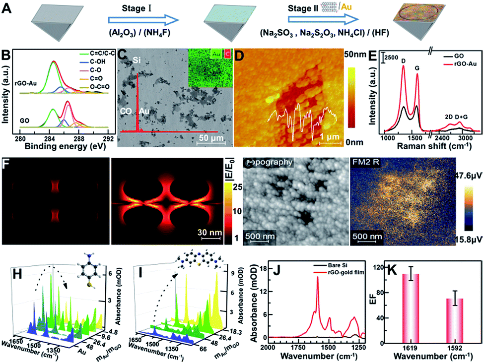 | ||
| Fig. 1 (A) Schematic of fabrication of the rGO-Au/Au plasmonic substrate on the Si prism. (B) The C1s XPS spectrum of rGO-Au/Au and GO with experimental (black line) and fitted curves (red line) including deconvoluted components. (C) SEM image, EDS spectrum and elemental mapping image of the rGO-Au/Au substrate (Au: green; C: red). (D) The typical AFM image of the rGO-Au/Au substrate and corresponding height profile. (E) Raman spectra of GO and rGO-Au/Au under 532 nm laser irradiation. (F) FDTD simulations of the electric field amplitude distribution |E/E0| of AuNPs/AuNPs and AuNPs/rGO/AuNPs at λ = 5.7 μm. (G) Mid-infrared near-field amplitude image of the as-prepared rGO-Au/Au substrate measured with s-SNOM at λ = 5.7 μm. (H and I) SEIRA spectra of p-ATP (10−3 M) and MB (10−5 M) molecules adsorbed on the rGO-Au/Au substrate prepared with different mass ratios of Au and GO. (J and K) A comparison of the enhanced spectra for 0.32 μg p-ATP with and without the rGO-Au/Au film on the Si prism (J) and the corresponding average enhancement factor (EF) at 1619 and 1592 cm−1 (K). | ||
To fully verify the role of graphene-enhanced plasmons in a local electromagnetic field, a simplified model of ellipsoid gold nanoparticles (R1 = 30 nm; R2 = 10 nm) obtained from the AFM image and a rGO layer of 4 nm thickness inferred from Raman data were built, and the corresponding local field distribution |E/E0| was simulated by the finite-difference time-domain (FDTD) method, as shown in Fig. 1E. Comparison of the X–Z views of the electric field amplitude distribution in both AuNPs/AuNPs and AuNPs/rGO/AuNPs shows that a stronger local field enhancement clearly appears between AuNP and rGO and at both sides of the AuNPs, indicating that the addition of rGO greatly enhances the local field intensity in the plasmonic hybrid structure.33,34 To further understand this phenomenon, scattering-type scanning near-field optical microscopy (sSNOM) was used to simultaneously map the topography and the near-field scattered intensity of the as-prepared rGO-Au/Au substrate at λ = 5.7 μm (Fig. 1F). In the infrared near-field image, the scattering amplitude of rGO-AuNP/Au located in the nanoscale pores shown in the topography image is much higher than that of the surrounding Au, possibly due to the rGO-mediated enhancement of the local electronic field and their coupling. The mass ratios of Au and GO could be tailored according to detection needs to obtain an optimal enhancement. For sulfhydryl-containing molecules such as p-aminothiophenol (p-ATP),35 which can form self-assembled monolayers on a gold surface by a favorable interaction between Au and sulfur groups, the maximum absorption of p-ATP can be obtained on the rGO-Au/Au substrates prepared by using gold and GO at a mass ratio of 26.4 (Fig. 1G). Meanwhile, for the detection of aromatic molecules like methylene blue (MB),36 which can be adsorbed on rGO via π–π stacking, the absorption was increased with the increase of the rGO content in the plasmonic substrate (Fig. 1H). Considering comprehensively, the mass ratio of (mAu/mGO = 26.4) was chosen for preparing the plasmonic substrate for further application. The enhancement effect was evaluated by comparing the characteristics of the deposited p-ATP (∼0.32 μg) onto the bare Si prism and rGO-Au/Au coated Si prism, respectively, at about monolayer thickness (Fig. 1I),25 which shows the enhancement factor of ∼110 and 72 times by comparing the peak intensity at 1619 and 1592 cm−1 (Fig. 1J).
Cell immobilization on the rGO-Au/Au substrate
To enhance the attachment of cells on the rGO-Au/Au substrate, we further modified the substrate with a biocompatible extracellular matrix PLL (Fig. 2A), because its flexible molecular backbone with plentiful active amino groups can bind tightly to negatively charged cell membranes.37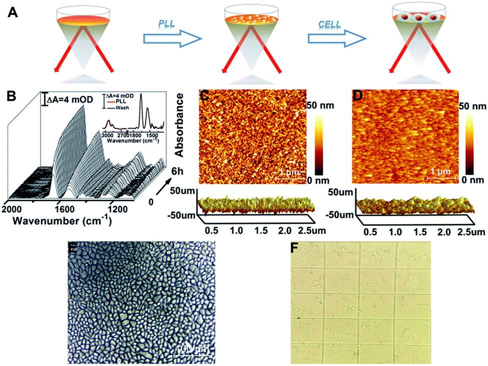 | ||
| Fig. 2 (A) Schematic of PLL coating and of HeLa cell assembly on the substrate. (B) Time-dependent SEIRA spectra of PLL were obtained by taking the rGO-Au/Au substrate immersed in H2O as a reference spectrum. Inset: comparison of spectra before and after washing with water. (C and D) The typical 2D and 3D AFM images of the microscopic features on the surface of the rGO-Au/Au film (C) and PLL coated rGO-Au/Au film (D). (E) An optical microscopy image showing a ∼100% confluent HeLa cell monolayer successfully immobilized on the rGO-Au/Au substrate. (F) The image of trypan blue exclusion test cells which were trypsinized from the rGO-Au/Au substrate. | ||
The PLL thin layer was well deposited on the substrate as proved by the in situ SEIRAS measurements. The SEIRA spectra show a gradual increase of the significant absorption feature of ν(CO) at 1660 cm−1 and the combination of N–H in-plane bending and the C–N stretching vibration at 1545 cm−1 at the beginning of 30 min and then a slower growth mode until reaching equilibrium (Fig. 2B).38,39 When washed with ultra-pure water six times after 6 h, the absorption intensity of PLL was almost unchanged, indicating that the PLL thin layer was formed and was stable (Fig. 2B, inset). This observation was in agreement with the AFM results showing that the root mean square roughness (Ra) decreases from 4.86 nm for the rGO-Au/Au film to 3.17 nm for the PLL monolayer (Fig. 2C). After introducing HeLa cells into the ATR chamber, cell attachment, growth, and proliferation occurred on the rGO-Au/Au surface coated with the PLL layer. An ∼100% confluent cell monolayer with a circular smooth and bright edge was observed in the AFM optical image (Fig. 2E), suggesting a good biocompatibility as confirmed using the trypan blue exclusion test (Fig. 2F), which showed about 99% viable cells.
The interaction of cells and PEG-coated CuS NPs monitored by SEIRAS
After this, the spectrum of cells immersed in 1 mL phosphate-buffered saline (PBS, pH = 7.4) was taken as the reference, and then sample spectra were measured as soon as the cells were exposed to 100 μg mL−1 PEG-CuS NPs.40 For comparison, the sample spectra following the addition of NPs with the spectrum of PLL coating as the reference were also recorded in PBS (Fig. 3A(a)). As can be seen, the SEIRA spectra induced by the addition of PEG-CuS NPs are significantly different in the presence and absence of cells, indicating that the spectra shown in Fig. 3A(b and c) were indeed caused by the interaction between HeLa cells and NPs, particularly at IR bands associated with proteins and phospholipids, which are not disturbed by structure peaks of PLL and adsorbed PEG-CuS NPs. After treating with CuS NPs for 2 h, cells still maintain good activity validated by cell viability experiments of MTT and the trypan blue exclusion test (Fig. S3†). Because the evanescent wave decays exponentially with the distance from the surface of the Si prism where single total infrared reflection occurs, IR light could penetrate into cell volume only at a very shallow depth, such that the observed SEIRA spectra should mostly come from the rearrangements of the cell membrane, such as membrane proteins, lipids etc.41,42 It is worthy to note that addition of newly prepared CuS NPs (CuS-new) will induce some characteristic peaks in the fingerprint region (Fig. 3A(b)) including the peaks at 1663 and 1542 cm−1 assigned to amide I and amide II band vibrations and the peaks at 1446–1358 cm−1 assigned to conformational changes of the lipid bilayer (Table S1†). However, addition of nanomaterials that have been preserved for more than 7 days (CuS-old) could induce a dramatic difference in the spectrum (Fig. 3A(c)). Two peaks appeared at 1500–1700 cm−1 with maxima at 1673 cm−1 and 1601 cm−1, respectively. The difference of amide I will be discussed vide infra. Surprisingly, the CuS-old-induced characteristic peaks in the fingerprint region (∼1673, 1601, 1558, 1446, 1391, and 1358 cm−1) are nearly consistent with those induced by addition of CuCl2 solution (Fig. 3A(d)), especially when the broad peak at 1601 cm−1 was analyzed by Gaussian curve fitting (Fig. S5†) suggesting that a similar interaction mode with copper ions happened. As we know, Cu is an indispensable trace element that drives various kinds of life activities.43 When cells uptake Cu, reduction of Cu occurs prior to its transport through the plasma membrane. First, Cu ions probably interacted with cell surface metalloreductases Fre1p/2p (heme-containing proteins, four histidine residues, etc.),44,45 which reduce Cu2+ (oxidized) to Cu+ (reduced) via the coordination of Cu2+ ions and nitrogen or oxygen donors.43 Subsequently, transmembrane copper transport protein 1 (Ctr1) coordinates Cu+ ions through the sulfur donor ligands43,46 in the high affinity methionine-rich domains “40MMMMPM45” and “150MLIFM154”. According to the mechanism discussed above, the absorption peak at 1601 cm−1 was very likely from the coordination of Cu2+ ions with nitrogen or oxygen donors such as from histidine moieties43,47 and/or from other components in the membrane. Indeed, the coordination of Cu2+ with nitrogen or oxygen donors could result in the absorption at about 1610–1580 cm−1.16,48,49 Therefore, the appearance of the 1601 cm−1 peak could be closely related to coordination of copper ions and the cell membrane, which also resulted in a similar conformational change of protein as reflected by an identical peak at 1673 cm−1.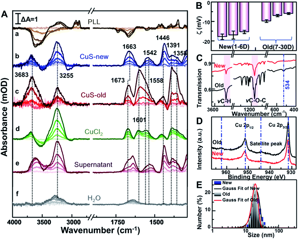 | ||
| Fig. 3 (A) The SEIRA difference spectra of (a) CuS NP induced PLL by taking the PLL layer modified substrate as a reference, and the difference spectra of HeLa cells induced by addition of (b) CuS-new NPs, (c) CuS-old NPs, (d) CuCl2, (e) the supernatant of CuS-old NPs and (f) only water as a control by taking the cell incubated substrate as a reference for 2 h, respectively. (B) The zeta potentials of PEG-CuS NPs at different times. (C) FTIR transmission spectra of the CuS-new NPs and CuS-old NPs. (D) Cu 2p XPS spectra of the CuS-new NPs and CuS-old NPs. (E) The hydrodynamic diameter distributions of CuS-new NPs and CuS-old NPs using the dynamic light scattering technique. | ||
Meanwhile, to identify if it comes from the free copper ions in the CuS-old solution, we further centrifuged the solution of CuS-old and recorded the spectrum induced by the interaction between the supernatant and cells (Fig. 2A(e)). However, we did not find characteristic peaks similar to those induced by copper ions. In contrast, the changes of characteristic peaks in the fingerprint region were similar to those induced by cell interaction with CuS-new nanoparticles. All of this suggests that the different peaks that have been induced by CuS-new and CuS-old nanoparticles originated from the difference in their surface properties, and have a relationship with copper ions.
To gain a more detailed understanding, we thoroughly characterized the PEG-CuS NPs. We found that zeta potential of newly prepared nanoparticles (Fig. 3B) remained nearly unchanged for 6 days (new), while it became more positive after 7 days and then became constant within 30 days (old), which is due to the dissociation of Cu ions from CuS and then coordination with PEG of CuS NPs because a clear ν(Cu–O) absorption peak at 534 cm−1 was observed in the FTIR spectrum of CuS-old NPs which was not observed for CuS-new NPs (Fig. 3C). In order to verify this, we further use the XPS technique, a useful analysis tool for characterizing surface element states, to detect different periods of CuS NPs. As we can see, in the XPS survey spectra (Fig. 3D), the more prominent satellite peaks for CuS-old NPs at around 944.2 eV and 962.6 eV demonstrate the existence of Cu(II) in the paramagnetic chemical state on the surface of CuS NPs,50 further indicating that more Cu2+ species existed on the surface of PEG-CuS NPs. Nevertheless, such changes in the surface properties only slightly changed the diameter of the PEG-CuS NPs (∼2 nm) as judged from dynamic light scattering (Fig. 3E). And a more detailed characterization of CuS-new NPs and CuS-old NPs is shown in Fig. S3† (including TEM, HRTEM, EDS, UV-Vis, etc.). We also noted that interaction of Cu ions (d) and CuS-new (b) with cells induced a strong peak at 3255 cm−1 and a weak peak at 3683 cm−1, which are assigned to vibrations of water molecules in an effective and disturbed hydrogen-bond network, respectively (Table S1†),51,52 and the absorption peak at 3250 cm−1 may also be attributed to the amide A band of the protein (Fig. S4†).53 The water peaks at 3255 cm−1 were also observed in the control group with only addition of 25 μL H2O (Fig. 3A(f)) possibly due to the influence of the plasma membrane surface potential (ψ) on the alignment of the interfacial water.54,55 Therefore, its strength is naturally affected by the different changes of local potential caused by the interaction of different substances with cell membranes. The appearance of the peak at 3683 cm−1 could be attributed to the penetration of water molecules into the hydrophobic region of the disordered lipid due to the interaction of the Cu ions and CuS-new NPs.56 It is worthy to note that the intensity of the peak was greatly enhanced after the cells interacted with CuS-old NPs.
To further reveal the origin of the difference, the intensities of peaks at 3255 and 3683 cm−1versus incubated time were dynamically tracked after addition of CuS-new and CuS-old NPs, respectively (Fig. 4A–D). For addition of CuS-new NPs, both peak intensities showed a linear increase (Fig. 4C); however, for addition of CuS-old NPs, the linear increase was only observed within the first 30 min, after which, the peak intensity at 3255 cm−1 remained nearly unchanged while the peak intensity at 3683 cm−1 showed a dramatic growth (Fig. 4D). For CuS-old NPs, the coordination of Cu2+ with PEG relative to that of CuS-new NPs will decrease the electronegativity of the NPs (Fig. 3B) and greatly weaken the electrostatic repulsion forces between NPs and the negatively charged cell plasma membrane, thus accelerating and increasing the adsorption of NPs on the cell membrane in the same period of time,4 which may result in the saturated adsorption within 30 min. The progressive adsorption of NPs could continually interrupt the conformation of the lipid and reorient the interfacial water molecules, resulting in a continuous change of the absorption of the interfacial water. After saturated adsorption, the strong hydrogen bond network among the water molecules near the cell membrane could remain relatively stable, resulting in unchanged intensity for the peak at 3255 cm−1. More interestingly, due to this phenomenon, the peak at 1577 cm−1 was gradually shifted to 1601 cm−1 with a similar tendency for the change of the peak intensity at 3683 cm−1 (Fig. 4C, blue line). Accompanied by the adsorption of CuS-old NPs on the surface of the cell membrane, the copper ions coordinated on the surface of the NPs also gradually approach the surface of the cell membrane and interact with the cell membrane, thus leading to the shift of the maximum absorption peak from ∼1577 cm−1 to 1601 cm−1 due to the coordination of Cu2+, which shows a similar tendency to that of the fast increase of the intensity for the peak at 3683 cm−1, suggesting that the interaction of surface Cu2+ caused a strong disturbance to the hydrogen-bond network of interfacial water. However, this phenomenon is dramatically different from that induced by pure Cu2+ interaction (Fig. 3A(d)). Considering the interaction between copper ions that coordinate on the surface of nanomaterials and cell membranes, it is possible that the significant enhancement of the absorption at 3683 cm−1 may be related to the endocytosis of nanomaterials. Therefore, the different spectral changes caused by the interaction of CuS-new NPs and CuS-old NPs with cells may reflect different uptakes.
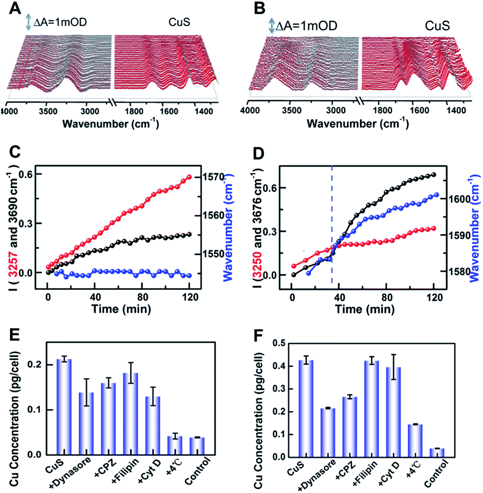 | ||
| Fig. 4 (A and B) The CuS-new NP (A) and CuS-old NP (B) induced SEIRA difference spectra by taking HeLa cells on the rGO-Au/Au substrate immersed in PBS as a reference. (C and D) IR peak intensity of interfacial water and the shifts of the maximum peak position at ∼1542 cm−1 were plotted as a function of time under the condition of (A) and (B), respectively. (E and F) ICP-MS results of Cu concentration per HeLa cell pretreated with dynasore, CPZ, filipin, and Cyt D at 4 °C and then treated with the CuS-new NP (E) and CuS-old NP (F) conditions, respectively, with untreated cells as the control. | ||
To prove this hypothesis, inductively coupled plasma mass spectroscopy (ICP-MS) was used to quantify the uptake of the two kinds of nanoparticles by HeLa cells (Fig. 4E and F), which shows an elevated content of Cu for CuS-old-treated cells compared with that of CuS-new-treated cells, suggesting an enhanced uptake of CuS NPs via internalization and membrane-bound possibly due to the strengthened association and binding avidity of NPs by exposed Cu ions on the surface of CuS NPs. Treatment of cells at 4 °C resulted in a dramatic decrease of the uptake of both NPs, suggesting energy-dependent endocytosis. If the cells were treated with chlorpromazine (CPZ, clathrin inhibitor) and dynasore (dynamin inhibitor), respectively, the cellular uptake of CuS-old NPs could be significantly inhibited, while having less effect on the uptake of CuS-new NPs. After treatment of cells with filipin (caveolae inhibitor) or Cyt D (inhibitor of actin polymerization related phagocytosis and clathrin/caveolin independent endocytosis), only the uptake of CuS-new NPs was affected by the treatment of Cyt D. These results demonstrate that the endocytosis of CuS-old NPs is mainly clathirin-mediated, while that of CuS-new NPs is through clathirin-mediated and clathrin- and caveolae-independent pathways. Interestingly, we found that dynasore and CPZ also affected the relative strength of water peaks induced by the interaction of CuS-old NPs with cells (Fig. S4†). The comparison of the ratio of peak intensity I3683/3255 in the presence and absence of inhibitors also indicates the clathirin-mediated endocytosis of CuS-old NPs (Fig. S4F†), which further suggests that the significant enhancement in the intensity of the peak at 3683 cm−1 could be induced by endocytosis of NPs. The intracellular membrane mass redistribution with NP internalization41 could facilitate the entry of hydrated PEG-CuS NPs into the hydrophobic backbone of the plasma membrane and then greatly enhance the amount of water molecules with disturbed hydrogen bonding.
SEIRAS study of photothermal-induced cell death
Compared with CuS-new NPs, the enhanced cell uptake of CuS-old NPs due to the weak electrostatic repulsion forces (Fig. 3B) as evaluated from the Cu content measured by ICP-MS (Fig. 4E and F) will inevitably enhance the photothermal effect, resulting in more cell death under the same power irradiation (Fig. 5A). To further reveal the molecular mechanism of such a difference, the hyperthermia-induced cellular spectra were monitored under 980 nm laser irradiation at 1 W cm−2 for 20 min by taking HeLa cells incubated with two kinds of PEG-CuS NPs at room temperature as reference spectra, respectively (Fig. 5B and C). For CuS-new NP treated cells, it is interesting to observe the opposite intensity changes of the ν(OH) stretching band of water molecules with an increase at ∼3610 cm−1 and a decrease at ∼3300 cm−1 as a function of illumination time (Fig. 5B, upper panel, red lines) possibly due to a lateral disordered orientation for the coupled multimer water to the lipid and the decrease of near-bulk water upon heating,51 just as the phenomena observed in the control groups PLL-coated (Fig. 5D) and NP-untreated cell-coated surface (Fig. 5E) under identical conditions. However, for CuS-old NP treated cells, the negative water band at ∼3300 cm−1 was partly recovered at the end (Fig. 5C). More significant is that the SEIRA spectra in the control groups were nearly recovered to the initial state after stopping the illumination (Fig. 5D and E, lower panel, blue lines); however, significant spectral changes can be observed in the fingerprint region for CuS-NP treated cells, suggesting that the disturbance to the interfacial water and the configuration of the cellular membrane could be recovered after the surface was gradually cooled without the effect of NPs. It is worthy to note that a more obvious peak appeared at 1709 cm−1 for the cells treated with CuS-old NPs (Fig. 5C, lower panel) than those treated with CuS-new NPs (Fig. 4B, lower panel), which could be the reason for the recovery of the negative peak at ∼3300 cm−1 as shown in Fig. 5C (upper panel).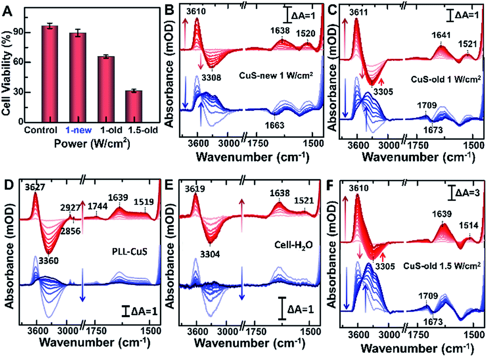 | ||
| Fig. 5 (A) Trypan blue exclusion test of cell viability without and with 980 nm irradiation (1 and 1.5 W cm−2). Time-dependent SEIRA spectra collected from CuS-new (B) and CuS-old (C) NP treated HeLa cells, the NP-treated PLL surface (D), the NP-untreated cell-coated surface (E) illuminated at 1 W cm−2 and CuS-old NP treated cells at 1.5 W cm−2 (F) on the rGO-Au/Au substrate by taking CuS incubated cells on the rGO-Au/Au substrate immersed in PBS as a reference. Red lines (upper panel, 0–20 min): at the start of the illumination; blue lines (lower panel, 0–20 min): at the end of the illumination. | ||
To further verify the hypothesis, we recorded the hyperthermia-induced cellular spectra under irradiation at 1.5 W cm−2 since such a condition could induce more cell death (Fig. 5A). Indeed, we observed that the peak at 1709 cm−1 appeared even under illumination, and the recovery of the negative peak was more obvious at ∼3300 cm−1, almost restored to the baseline level (Fig. 5F, upper panel). A positive-going band at 1709 cm−1 may be assigned to ν(CO) stretching vibration of phosphatidylserine (PS),57 a spectral marker of apoptosis associated with membrane changes such as the loss of membrane phospholipid asymmetry, cell shrinkage and cell membrane blubbing (Fig. S5D†). These cell membranes flip from the inner to the outer surface of the plasma membrane (vide infra) and could further bind water molecules to rearrange the H-bonding network near the cellular membrane along with the newly entered water molecules after cell contraction.
To further reveal the mechanism of apoptosis, we carefully compared the steady-state SEIRA spectra of cells treated with different nanoparticles and after stopping irradiation and cooling to room temperature (Fig. 6). In addition to the positive peak at 1709 cm−1, the obviously negative peaks in amide I and amide II and ν(CH3) regions further indicate that the cell adhered to the extracellular matrix was partially desorbed from the surface as water molecules moved into the interface accompanied by an increase in the intensity of the interfacial water at 3000–3800 cm−1,56 and at this time, cells lost their bioactivities and underwent apoptosis.40 The inconsistent maximally negative peak of amide I at 1673 cm−1 and 1663 cm−1 produced by the cells treated with CuS-old and CuS-new NPs might suggest the different membrane protein receptors for CuS-old and CuS-new NP binding. Based on the above analysis of the ICP results, CuS NPs will adopt different endocytosis pathways at different stages. The clathirin-mediated endocytosis of CuS-old NPs is mainly through the membrane protein receptor YxxΦ (tyrosine-amino acid-hydrophobic residue) mediated by the AP2 μ2 fragment with an elongated banana-shaped seven-bladed β propeller, leading to the maximum peak position of amide I closer to 1673 cm−1 (Table S1†).58,59 Because of the coordination of Cu ions with CuS-old NPs, the surface Cu ions could also bind to certain membrane proteins.43 In comparison, the clathrin- and caveolae-independent pathways have a significant influence on endocytosis of CuS-new NPs, but the mechanisms remain poorly understood.60,61 However, compared with different peak positions, we believe that the protein receptors they act on are different.
 | ||
| Fig. 6 Comparison of the steady-state SEIRA spectra of cells treated with CuS-new (black) and CuS-old (red) after stopping irradiation by taking CuS incubated cells on the rGO-Au/Au substrate immersed in PBS as a reference, and the spectrum of Phe dissolved in PBS and then dried on the Si wafer (blue). Inset: magnified spectra ranging from 1675 cm−1 to 1465 cm−1 with peak fitting. | ||
According to the reported results, the inhibition of the phenylalanine (Phe) metabolism pathway could elevate the levels of Phe, its derivatives or contained peptides, thus inducing cell apoptosis during PTT therapy.62,63 Interestingly, several positive peaks did appear between negative peaks of amide I and amide II (Fig. 6, red line), proving that some molecules approach the surface of the substrate while membrane protein receptors move from the surface of the substrate. Thus, we have carefully analyzed the spectra between 1675 cm−1 and 1465 cm−1 with peak fitting processing in the Fig. 6 inset. Compared to the characteristic spectral pattern of chemical fingerprint absorption peaks of hydrophobic aromatic amino acids – Phe at ∼1643, 1622, 1587 and 1495 cm−1, which are attributed to the ring substituent ν(CO), δ(NH2), ν(CC) ring vibration (Table S2†), we found that these characteristic absorption peaks are basically consistent with steady-state SEIRA spectra of cells after PTT.64,65 The results demonstrate that Phe metabolism should be disturbed in cell apoptosis. Additionally, according to the cell phenotype, apoptosis was induced by the mitochondrial mediated Rho/ROCK pathway, in which myosin phosphatase target subunit 1 was cleaved by caspase-3 at Asp-884 to inhibit myosin II binding, and this will lead to an increasing phenylalanine levels in cells.62 The loss of selective permeability and the cellular membrane becoming more permeable upon apoptosis may result in the leakage of intracellular Phe66 and is thus detectable by SEIRAS together with the signal of some buried hydrophobic amino acids exposed during protein inactivation.63
Conclusions
Here, we construct a hybrid plasma film of Au decorated with a rGO-Au nanostructure via simultaneous reduction of NaAuClO4 and GO solution on the Si substrate, which displays an enhanced local electromagnetic field and good biocompatibility to the attached living cells, thus allowing monitoring in situ and in real time the interaction between NPS and living cells by SEIRAS. According to the fingerprint characteristics of SEIRAS, we could reveal that copper ions produced during the degradation of CuS NPs can cooperate with PEG modified on the surface of nanoparticles, which can significantly change the surface properties of nanomaterials and thus change the interaction with cells. The coordinated copper ions significantly reduce the electronegativity of nanomaterials, thus reducing the repulsion between materials and cell membranes and accelerating their interaction. The interaction between copper ions on the surface of materials and cell membranes changes the pathway of materials entering cells, increases the uptake of materials by cells, and enhances the water content of weak hydrogen bonding at the interface of cell membranes during endocytosis. Photothermal effect can transfer intracellular phospholipids to extracellular space, further changing the arrangement of interface water, meanwhile increasing the content of hydrophobic phenylalanine, which can induce apoptosis. The high sensitivity and fingerprint characteristics enable SEIRAS to reveal dynamic changes of the surface properties of PEG-coated CuS NPs and how they alter the interaction of nanomaterials with living cells for the first time.Experimental section
Preparation of the rGO-Au-decorated Au plasmonic substrate
The Au film decorated with rGO-Au (rGO-Au/Au) was electroless deposited onto the Si prism or wafer, which was polished with an Al2O3 slurry (1.0 μm), followed by washing thoroughly with deionized water. After immersion in a 40 wt% NH4F aqueous solution for 3 min, the rGO-Au/Au film was prepared by exposing the treated surface to a 1![[thin space (1/6-em)]](https://www.rsc.org/images/entities/char_2009.gif) :1:1 (v/v/v) mixture of 0.3 M Na2SO3 + 0.1 M Na2S2O3 + 0.1 M NH4Cl, 3% HF, and 1.2 mg mL−1 NaAuCl4 aqueous solution mixed with 2.5 mg mL−1 GO for 4 min at 55 °C. The obtained substrate was cleaned by electrochemical oxidation–reduction scanning in 0.1 M H2SO4 solution over the potential range of 0.1–1.4 V versus Ag/AgCl. At last, the rGO-Au/Au film coated Si prism was mounted on a home-built poly(trifluorochloroethylene) cell with a Viton O-ring. In order to obtain the desired enhancement effect for sulfhydryl and aromatic molecules, the NaAuCl4 aqueous solution mixed with different masses of GO dispersion (mAu/mGO = 4.8–66) was used to detect p-aminothiophenol (p-ATP) and methylene blue (MB) molecules.
:1:1 (v/v/v) mixture of 0.3 M Na2SO3 + 0.1 M Na2S2O3 + 0.1 M NH4Cl, 3% HF, and 1.2 mg mL−1 NaAuCl4 aqueous solution mixed with 2.5 mg mL−1 GO for 4 min at 55 °C. The obtained substrate was cleaned by electrochemical oxidation–reduction scanning in 0.1 M H2SO4 solution over the potential range of 0.1–1.4 V versus Ag/AgCl. At last, the rGO-Au/Au film coated Si prism was mounted on a home-built poly(trifluorochloroethylene) cell with a Viton O-ring. In order to obtain the desired enhancement effect for sulfhydryl and aromatic molecules, the NaAuCl4 aqueous solution mixed with different masses of GO dispersion (mAu/mGO = 4.8–66) was used to detect p-aminothiophenol (p-ATP) and methylene blue (MB) molecules.
To evaluate the enhancement factor (EF) of the rGO-Au/Au plasmonic substrate, a reference spectrum of the bare Si or rGO-Au/Au-coated Si prism was first recorded and then ∼0.32 μg (∼monolayer thickness)25 of p-ATP ethanol solution was dropped on the surface of the bare Si and rGO-Au/Au-coated Si prism, respectively. The sample spectra were recorded until total evaporation of ethanol by averaging 521 scans at a spectral resolution of 4 cm−1.
Immobilization of cells on the rGO-Au/Au film
Before culturing HeLa cells, the home-made poly(trifluorochloroethylene) cell and necessary experimental tools were sterilized with 70% ethanol under UV irradiation. 2 mL of cell suspension (5 × 10⁵ cell per mL) was seeded on the poly-L-lysine layer (0.1 mg mL−1 PLL) modified rGO-Au/Au film. After incubation for 24 h, the IR cell was mounted on a SEIR spectrometer. After washing three times with PBS, cells were exposed to 100 μg mL−1 of PEG-CuS NPs by adding 25 μL PEG-CuS NP aqueous solution (4 mg mL−1) into a volume of 1 mL of PBS.40 CuS NP induced SEIRA spectra were obtained by taking cells in PBS as a reference spectrum. After incubation with 100 μg mL−1 PEG-CuS NPs for 2 h, the cells were washed three times with PBS, followed by irradiation for 20 min using a 980 nm diode laser with a power of 1 and 1.5 W cm−2. As the control experiments, 25 μL H2O, the supernatant of CuS NPs (20 day) and 5 mM CuCl2 were used to replace CuS NPs and added into the ATR chambers. Unless noted specifically, the control experiments were performed following the same protocol and each measurement was repeated in triplicate.Cell viability on the rGO-Au/Au substrate was roughly assessed using a top-view optical microscope for cell monolayer integrity and morphology, and the trypan blue exclusion test to stain dead cells. Cells were trypsinized and resuspended in trypan blue (0.4%, g ml−1) for 3 min. Cell viability was calculated under 10× magnification using a hematocytometer. The percentage of cell viability was calculated as follows: Nviable cells/Ntotal cells × 100%.
To more directly explore the endocytic mechanism of CuS-PEG NPs internalized into HeLa cells, cells were pretreated with various inhibitors including dynasore (30 μg mL−1, dynamin inhibitor), chlorpromazine (CPZ, 10 μg mL−1, clathrin inhibitor), filipin (10 μg mL−1, caveolae inhibitor), and Cyt D (1 μmol L−1, an inhibitor of actin polymerization related phagocytosis and clathrin/caveolin independent endocytosis) for 1 h at 25 °C or 4 °C (energy independent pathway). After culturing with CuS-PEG NPs, cells were washed with PBS three times, trypsinized, resuspended, counted, and centrifuged, and the cell pellet was digested in 1 mL of aqua regia (VHCl:VHNO3 = 3:1). Cell concentrations were determined by hemacytometry and the intracellular copper content was quantified using ICP-MS with parts per billion sensitivity. In control, cells were placed in 1 mL PBS without nanoparticles.
Simulation
To simplify, the ellipsoid gold nanoparticle (R1 = 30 nm; R2 = 10 nm) obtained from the AFM image and a rGO layer of 4 nm thickness inferred from Raman data were considered, and simulation was performed by using the 3D finite-difference time-domain (FDTD) method on the basis of time varying electromagnetic Maxwell's equations.33,34 The incident light with a wavelength range from 2.5 to 10 μm propagating along the z direction was normally illuminated on the surface. Periodic boundary conditions and perfectly matched layer conditions were used to evaluate near-field enhancement data |E/E0| of the rGO-Au/Au film. The optical permittivity parameters of Au and rGO used in simulation were extracted from the data of Palik and Hwang.67,68Plasmon nano-imaging
Scattering-type scanning near-field optical microscopy (s-SNOM, Molecular Vista) used for this work was based on an AFM probe (a gold coated Si cantilever, 70 nm tapping amplitude and 270 kHz resonance frequency), which was illuminated by focused infrared light from a pulsed quantum cascade laser (QCL, Block Engineering). The plasmon nano-imaging of the sample could be obtained simultaneously via mapping the topography and the near-field scattered intensity detected using a liquid-nitrogen-cooled MCT detector. In order to suppress near field contribution from the tip-sample region, a versatile “Generalized Lock-In Amplifier” (GLIA) approach, which calculates the amplitude and phase of the scattered field, was used in the first harmonic modulation.25,69Conflicts of interest
There are no conflicts to declare.Acknowledgements
This work was financially supported by the Joint Sino-German Research Projects (21761132028), the National Natural Science Foundation of China (21675149, 21705146, 21874125, and 21877107), the Key Research Program of Frontier Sciences, CAS (QYZDY-SSW-SLH019), and the Science and Technology Development Program of Jilin Province (20170414037GH and 20190201074JC), and K. C. Wong Education Foundation.Notes and references
- G. Brumfiel, Nature, 2003, 424, 246 CrossRef CAS PubMed.
- M. Ferrari, Nat. Rev. Cancer, 2005, 5, 161 CrossRef CAS PubMed.
- L. A. Dykman and N. G. Khlebtsov, Chem. Rev., 2013, 114, 1258–1288 CrossRef PubMed.
- A. Albanese, P. S. Tang and W. C. W. Chan, Annu. Rev. Biomed. Eng., 2012, 14, 1–16 CrossRef CAS PubMed.
- H. K. Baca, C. Ashley, E. Carnes, D. Lopez, J. Flemming, D. Dunphy, S. Singh, Z. Chen, N. G. Liu, H. Y. Fan, G. P. Lopez, S. M. Brozik, M. Werner-Washburne and C. J. Brinker, Science, 2006, 313, 337–341 CrossRef CAS PubMed.
- A. Albanese, C. D. Walkey, J. B. Olsen, H. Guo, A. Emili and W. C. Chan, ACS Nano, 2014, 8, 5515–5526 CrossRef CAS PubMed.
- P. Dogra, N. L. Adolphi, Z. Wang, Y.-S. Lin, K. S. Butler, P. N. Durfee, J. G. Croissant, A. Noureddine, E. N. Coker, E. L. Bearer, V. Cristini and C. J. Brinker, Nat. Commun., 2018, 9, 1–14 CrossRef CAS PubMed.
- L. Guo, I. Panderi, D. D. Yan, K. Szulak, Y. Li, Y. T. Chen, H. Ma, D. B. Niesen, N. Seeram, A. Ahmed, B. Yan, D. Pantazatos and W. Lu, ACS Nano, 2013, 7, 8780–8793 CrossRef CAS PubMed.
- Y. Yong, X. J. Cheng, T. Bao, M. Zu, L. Yan, W. Y. Yin, C. C. Ge, D. L. Wang, Z. J. Gu and Y. L. Zhao, ACS Nano, 2015, 9, 12451–12463 CrossRef CAS PubMed.
- B. Ding, Y. Tian, Y. Pan, Y. Shan, M. Cai, H. Xu, Y. Sun and H. Wang, Nanoscale, 2015, 7, 7545–7549 RSC.
- P. R. Griffiths and J. A. De Haseth, in Fourier transform infrared spectrometry, ed. J. D. Winefordner, Springer International Publishing, 2007, pp. 2379–2380 Search PubMed.
- H. Muhamadali, M. Chisanga, A. Subaihi and R. Goodacre, Anal. Chem., 2015, 87, 4578–4586 CrossRef CAS PubMed.
- M. J. Baker, J. Trevisan, P. Bassan, R. Bhargava, H. J. Butler, K. M. Dorling, P. R. Fielden, S. W. Fogarty, N. J. Fullwood, K. A. Heys, C. Hughes, P. Lasch, P. L. Martin-Hirsch, B. Obinaju, G. D. Sockalingum, J. Sulé-Suso, R. J. Strong, M. J. Walsh, B. R. Wood, P. Gardner and F. L. Martin, Nat. Protoc., 2014, 9, 1771–1791 CrossRef CAS PubMed.
- D. R. Whelan, K. R. Bambery, L. Puskar, D. McNaughton and B. R. Wood, Analyst, 2013, 138, 3891–3899 RSC.
- X. Jiang, E. Zaitseva, M. Schmidt, F. Siebert, M. Engelhard, R. Schlesinger, K. Ataka, R. Vogel and J. Heberle, Proc. Natl. Acad. Sci. U. S. A., 2008, 105, 12113–12117 CrossRef CAS PubMed.
- A. Barth, Biochim. Biophys. Acta, Bioenerg., 2007, 1767, 1073–1101 CrossRef CAS PubMed.
- D. C. Fernandez, R. Bhargava, S. M. Hewitt and I. W. Levin, Nat. Biotechnol., 2005, 23, 469–474 CrossRef CAS PubMed.
- K. L. A. Chan and S. G. Kazarian, Chem. Soc. Rev., 2016, 45, 1850–1864 RSC.
- B. R. Wood, L. Chiriboga, H. Yee, M. A. Quinn, D. McNaughton and M. Diem, Gynecol. Oncol., 2004, 93, 59–68 CrossRef CAS PubMed.
- C. Lima, V. Goulart, L. Côrrea, T. Pereira and D. Zezell, Int. J. Mol. Sci., 2015, 16, 6621–6630 CrossRef CAS PubMed.
- M. Osawa, in Surface-enhanced infrared absorption, ed. S. Kawata, Springer International Publishing, 2001, pp. 163–187 Search PubMed.
- L. Wu, L. Zeng and X. Jiang, J. Am. Chem. Soc., 2015, 137, 10052–10055 CrossRef CAS PubMed.
- Y. Liu, W. J. Bao, Q. W. Zhang, J. Li, J. Li, J. J. Xu, X. H. Xia and H. Y. Chen, Anal. Chem., 2018, 90, 12979–12985 CrossRef CAS PubMed.
- S. Lal, N. K. Grady, J. Kundu, C. S. Levin, J. B. Lassiter and N. J. Halas, Chem. Soc. Rev., 2008, 37, 898–911 RSC.
- F. J. Cao, L. Wu, Y. D. Ruan, J. Bai and X. E. Jiang, Anal. Chem., 2018, 90, 6526–6531 CrossRef CAS PubMed.
- Y. Li, Q. Lu, H. Liu, J. Wang, P. Zhang, H. Liang, L. Jiang and S. Wang, Adv. Mater., 2015, 27, 6848–6854 CrossRef CAS PubMed.
- J. Chen, B. Yao, C. Li and G. Shi, Carbon, 2013, 64, 225–229 CrossRef CAS.
- D. R. Dreyer, S. Park, C. W. Bielawski and R. S. Ruoff, Chem. Soc. Rev., 2010, 39, 228–240 RSC.
- M. Iliut, C. Leordean, V. Canpean, C.-M. Teodorescu and S. Astilean, J. Mater. Chem. C, 2013, 1, 4094 RSC.
- K. N. Kudin, B. Ozbas, H. C. Schniepp, R. K. Prud'homme, I. A. Aksay and R. Car, Nano Lett., 2008, 8, 36–41 CrossRef CAS PubMed.
- S. Stankovich, D. A. Dikin, R. D. Piner, K. A. Kohlhaas, A. Kleinhammes, Y. Jia, Y. Wu, S. T. Nguyen and R. S. Ruoff, Carbon, 2007, 45, 1558–1565 CrossRef CAS.
- G. Eda, G. Fanchini and M. Chhowalla, Nat. Nanotechnol., 2008, 3, 270–274 CrossRef CAS PubMed.
- Y. Wang, H. Chen, M. Sun, Z. Yao, B. Quan, Z. Liu, Y. Weng, J. Zhao, C. Gu and J. Li, Carbon, 2017, 122, 98–105 CrossRef CAS.
- W. J. Bao, Z. D. Yan, M. Wang, Y. Zhao, J. Li, K. Wang, X. H. Xia and Z. L. Wang, Chem. Commun., 2014, 50, 7787–7789 RSC.
- M. Osawa, N. Matsuda, K. Yoshii and I. Uchida, J. Phys. Chem., 1994, 98, 12702–12707 CrossRef CAS.
- Z. Q. Yu and S. S. C. Chuang, J. Phys. Chem. C, 2007, 111, 13813–13820 CrossRef CAS.
- J. Varani, D. R. Inman, S. E. G. Fligiel and W. J. Hillegas, Cytotechnology, 1993, 13, 89–98 CrossRef CAS PubMed.
- G. Ramer, A. Balbekova, A. Schwaighofer and B. Lendl, Anal. Chem., 2015, 87, 4415–4420 CrossRef CAS PubMed.
- C. S. Shan, H. F. Yang, D. X. Han, Q. X. Zhang, A. Ivaska and L. Niu, Langmuir, 2009, 25, 12030–12033 CrossRef CAS PubMed.
- P. L. Fale, A. Altharawi and K. L. A. Chan, Biochim. Biophys. Acta, Mol. Cell Res., 2015, 1853, 2640–2648 CrossRef CAS PubMed.
- T. Suutari, T. Silen, D. Şen Karaman, H. Saari, D. Desai, E. Kerkelä, S. Laitinen, M. Hanzlikova, J. M. Rosenholm, M. Yliperttula and T. Viitala, Small, 2016, 12, 6289–6300 CrossRef CAS PubMed.
- J. Li, B. Zheng, Q.-W. Zhang, Y. Liu, C.-F. Shi, F.-B. Wang, K. Wang and X.-H. Xia, Journal of Analysis and Testing, 2017, 1, 1–8 CrossRef.
- B.-E. Kim, T. Nevitt and D. J. Thiele, Nat. Chem. Biol., 2008, 4, 176–185 CrossRef CAS PubMed.
- E. Georgatsou and D. Alexandraki, Yeast, 1999, 15, 573–584 CrossRef CAS PubMed.
- A. A. Finegold, K. P. Shatwell, A. W. Segal, R. D. Klausner and A. Dancis, J. Biol. Chem., 1996, 271, 31021–31024 CrossRef CAS PubMed.
- T. Furukawa, M. Komatsu, R. Ikeda, K. Tsujikawa and S. Akiyama, Curr. Med. Chem., 2008, 15, 3268–3278 CrossRef CAS PubMed.
- J. Gerbrand Mesu, T. Visser, F. Soulimani, E. E. van Faassen, P. de Peinder, A. M. Beale and B. M. Weckhuysen, Inorg. Chem., 2006, 45, 1960–1971 CrossRef PubMed.
- J. G. Mesu, T. Visser, F. Soulimani, E. E. van Faassen, P. de Peinder, A. M. Beale and B. M. Weckhuysen, Inorg. Chem., 2006, 45, 1960–1971 CrossRef CAS PubMed.
- R. Falahat, M. Wiranowska, R. Toomey and N. Alcantar, Vib. Spectrosc., 2016, 87, 164–172 CrossRef CAS.
- B. Ma, S. Wang, F. Liu, S. Zhang, J. Duan, Z. Li, Y. Kong, Y. Sang, H. Liu, W. Bu and L. Li, J. Am. Chem. Soc., 2018, 141, 849–857 CrossRef PubMed.
- H. Binder, Eur. Biophys. J., 2006, 36, 265–279 CrossRef PubMed.
- M. J. Stein, T. Weidner, K. McCrea, D. G. Castner and B. D. Ratner, J. Phys. Chem. B, 2009, 113, 11550–11556 CrossRef CAS PubMed.
- D. Naumann, Infrared Spectroscopy of Cells, Tissues, and Biofluids, Springer, 2013 Search PubMed.
- X. Cong, M. F. Poyton, A. J. Baxter, S. Pullanchery and P. S. Cremer, J. Am. Chem. Soc., 2015, 137, 7785–7792 CrossRef CAS PubMed.
- L. Zeng, Chem.–Eur. J., 2017, 23, 15491–15497 CrossRef CAS PubMed.
- Y. Nagata and S. Mukamel, J. Am. Chem. Soc., 2010, 132, 6434–6442 CrossRef CAS PubMed.
- B. B. Wu, Y. P. Gong, X. H. Wu, Y. Y. Chen, F. F. Chen, L. T. Jin, B. R. Cheng, F. Hu and B. Xiong, J. Transl. Med., 2015, 13, 108 CrossRef PubMed.
- M. Marsh and H. T. McMahon, Science, 1999, 285, 215–220 CrossRef CAS PubMed.
- L. M. Traub, M. A. Downs, J. L. Westrich and D. H. Fremont, Proc. Natl. Acad. Sci. U. S. A., 1999, 96, 8907–8912 CrossRef CAS PubMed.
- S. D. Conner and S. L. Schmid, Nature, 2003, 422, 37–44 CrossRef CAS PubMed.
- R. G. Anderson and K. Jacobson, Science, 2002, 296, 1821–1825 CrossRef CAS PubMed.
- M. R. K. Ali, Y. Wu, T. Han, X. Zang, H. Xiao, Y. Tang, R. Wu, F. M. Fernández and M. A. El-Sayed, J. Am. Chem. Soc., 2016, 138, 15434–15442 CrossRef CAS PubMed.
- M. Aioub and M. A. El-Sayed, J. Am. Chem. Soc., 2016, 138, 1258–1264 CrossRef CAS PubMed.
- L. K. Tamm and S. A. Tatulian, Q. Rev. Biophys., 1997, 30, 365–429 CrossRef CAS PubMed.
- S. Y. Venyaminov and N. N. Kalnin, Biopolymers, 1990, 30, 1243–1257 CrossRef CAS PubMed.
- H. Hagberg, A. Lehmann, M. Sandberg, B. Nyström, I. Jacobson and A. Hamberger, J. Cereb. Blood Flow Metab., 1985, 5, 413–419 CrossRef CAS PubMed.
- E. Jung, S. Lee, S. Roh, E. Hwang, J. Lee, H. Lee and J. Hwang, J. Phys. D: Appl. Phys., 2014, 47, 265306 CrossRef.
- E. D. Palik, Handbook of optical constants of solids, Academic press, New York, 1998 Search PubMed.
- A. Bruyant, J. Vaillant, T.-H. Wu, Y. Zhu, Y. Huang and A. Al Mohtar, Interferometry Using Generalized Lock-in Amplifier (G-LIA): A Versatile Approach for Phase-Sensitive Sensing and Imaging, inTech, Croatia, 2017 Search PubMed.
Footnote |
| † Electronic supplementary information (ESI) available. See DOI: 10.1039/c9na00371a |
| This journal is © The Royal Society of Chemistry 2019 |