
 Open Access Article
 This Open Access Article is licensed under a Creative Commons Attribution-Non Commercial 3.0 Unported Licence
Two-dimensional graphene paper supported flexible enzymatic fuel cells†
Fei
Shen
a,
Dmitry
Pankratov
 a,
Arnab
Halder
a,
Xinxin
Xiao
a,
Miguel D.
Toscano
b,
Jingdong
Zhang
a,
Jens
Ulstrup
a,
Lo
Gorton
c and
Qijin
Chi
*a
a,
Arnab
Halder
a,
Xinxin
Xiao
a,
Miguel D.
Toscano
b,
Jingdong
Zhang
a,
Jens
Ulstrup
a,
Lo
Gorton
c and
Qijin
Chi
*a
aDepartment of Chemistry, Technical University of Denmark, DK-2800 Kongens Lyngby, Denmark. E-mail: cq@kemi.dtu.dk; Tel: +45 45252302
bNovozymes A/S, Krogshoejvej 36, 2880 Bagsværd, Denmark
cDepartment of Biochemistry and Structural Biology, Lund University, P.O. Box 124, SE-22100 Lund, Sweden
First published on 10th May 2019
Abstract
Application of enzymatic biofuel cells (EBFCs) in wearable or implantable biomedical devices requires flexible and biocompatible electrode materials. To this end, freestanding and low-cost graphene paper is emerging among the most promising support materials. In this work, we have exploited the potential of using graphene paper with a two-dimensional active surface (2D-GP) as a carrier for enzyme immobilization to fabricate EBFCs, representing the first case of flexible graphene papers directly used in EBFCs. The 2D-GP electrodes were prepared via the assembly of graphene oxide (GO) nanosheets into a paper-like architecture, followed by reduction to form layered and cross-linked networks with good mechanical strength, high conductivity and little dependence on the degree of mechanical bending. 2D-GP electrodes served as both a current collector and an enzyme loading substrate that can be used directly as a bioanode and biocathode. Pyrroloquinoline quinone dependent glucose dehydrogenase (PQQ-GDH) and bilirubin oxidase (BOx) adsorbed on the 2D-GP electrodes both retain their biocatalytic activities. Electron transfer (ET) at the bioanode required Meldola blue (MB) as an ET mediator to shuttle electrons between PQQ-GDH and the electrode, but direct electron transfer (DET) at the biocathode was achieved. The resulting glucose/oxygen EBFC displayed a notable mechanical flexibility, with a wide open circuit voltage range up to 0.665 V and a maximum power density of approximately 4 μW cm−2 both fully competitive with reported values for related EBFCs, and with mechanical flexibility and facile enzyme immobilization as novel merits.
Introduction
Rapid development of portable microelectronics for biomedical purposes has increasingly demanded miniature power sources that facilitate long-term operation under biological environments such as physiological and pseudo-physiological conditions. Such power-source systems are particularly needed for low-power biomedical devices, e.g. cardiac pacemakers, urinary sphincters and integrated biosensing devices for periodic monitoring of diseases.1–3Enzymatic biofuel cells (EBFCs) constitute a kind of sustainable bioelectrochemical devices that convert chemical energy into electric power using enzymes as highly efficient and selective biological catalysts and remarkably, they can operate under neutral pH conditions with high selectivity towards conversion of targeted chemical fuels. These unique characters make EBFCs promising power systems for implantable biomedical devices,4,5 in which low power is sufficient but mechanical flexibility, biocompatibility and implantability are crucial. Furthermore, a rich variety of dissolved fuels and oxidants (e.g., glucose, lactate, urate and oxygen) and intensive flow rate make human blood the most attractive internal fluid for EBFC operation.6 The possibility of operating EBFCs in various physiological media of humans and other mammals has recently been demonstrated at versatile in vitro,7–10ex vivo6 and in vivo levels.1,11,12
Electrode materials are central in the development of high-performance EBFCs. Indeed, recent advances in the field of EBFCs have been driven mainly by the design and assembly of three-dimensional (3D) porous and high surface-area electrode materials.13,14 However, these bioelectrodes can hardly be integrated into blood or other biological vessels. Additionally, for biological tests they require a membrane to prevent clogging by blood cells and possible formation of cholesterol plaques or other structures that could affect the blood circulation and induce thrombosis or embolism.1,4 In many low-power electronics applications, the EBFC power density might not be a key factor, since as demonstrated by nanocomposite based EBFCs the power density achieved is far higher than that for practical needs.15 However, the (re)production of these nano-architectures in the centimeter scale is complicated and costly. In addition, intensive consumption of glucose and oxygen by an EBFC needed for generating high current density is very likely to cause local hypoxia and even cell death. The power output from an implanted EBFC should therefore be only as low as needed to power the targeted device. To date, for example, the highest power output achieved for EBFCs in blood mimicking glucose-containing buffer solutions is close to 1000 μW cm−2, i.e. reaching ca. 130 μW cm−2 in whole human blood.16 This value is significantly higher than required to power most modern cardiac pacemakers (only 1–10 μW needed).4,17 In contrast, research efforts toward scalable two-dimensional (2D) materials for potentially implantable bioelectronics are clearly underplayed, although the advantages of 2D materials as a freestanding support for non-enzymatic sensors,18,19 enzyme biosensors20,21 microbial biofuel cells22,23 and others24,25 have been clearly demonstrated.
Graphene based nanocomposites, arguably now the most broadly used 2D materials, have offered new opportunities for the immobilization of various enzymes, mainly because of their high electrical conductivity, high surface area, good mechanical strength, tunable mechanical flexibility, and good biological compatibility.26,27 An increasing number of researchers have explored graphene and its composites for enzyme immobilization. For example, Di Bari et al. reported the electrodeposition of graphene oxide (GO) on glassy carbon (GC) electrodes to construct 3D electrodes of high surface-area, which were further functionalized for covalent attachment of multi-copper oxidases (MCOs).28 Inamuddin et al. developed a bioanode using layer-by-layer assembly of sulfonated graphene/ferritin/glucose oxidase biocomposite films for mediated electron transfer (MET) driving oxidation of glucose.29 However, graphene and its hybrids could not self-support (or be freestanding) in this research, but needed to be supported by GC or gold electrodes.28–31 These graphene-modified electrodes are therefore largely limited to lab-level tests and can hardly be used for fabricating practical devices due to their non-scalability and high cost. In order to overcome this limitation, flexible, maneuverable or even implantable supporting electrodes are needed to replace the rigid (GC and graphite) or expensive (gold and platinum) working electrodes for design and fabrication of new-generation EBFCs which can favor biomedical applications.
In this work, we have engineered flexible and freestanding graphene papers with a 2D active surface (2D-GP) by a novel low-cost solution-processing procedure. The resulting graphene papers were tested as a support for both the biocathode and bioanode to create a flexible, membrane-free and potentially implantable glucose/O2 EBFC. As illustrated in Scheme 1, the main building blocks include pyrroloquinoline quinone-dependent glucose dehydrogenase (PQQ-GDH), bilirubin oxidase (BOx), GO nanosheets and the ET mediator Meldola blue (MB) (Scheme 1A). Engineered 2D-GP enabled facile immobilization of both enzymes via direct adsorption with their biocatalytic activities fully retained. PQQ-GDH required MB as an ET mediator to act as an anode biocatalyst for electrocatalytic oxidation of glucose, but adsorbed BOx can exchange electrons with the 2D-GP cathode via direct ET (DET) toward electrocatalytic reduction of dioxygen. The assembled EBFCs exhibited high performance and stability. To the best of our knowledge, this work represents the first exploration of graphene paper as a self-supporting electrode material for flexible and membrane-free glucose/O2 EBFCs.
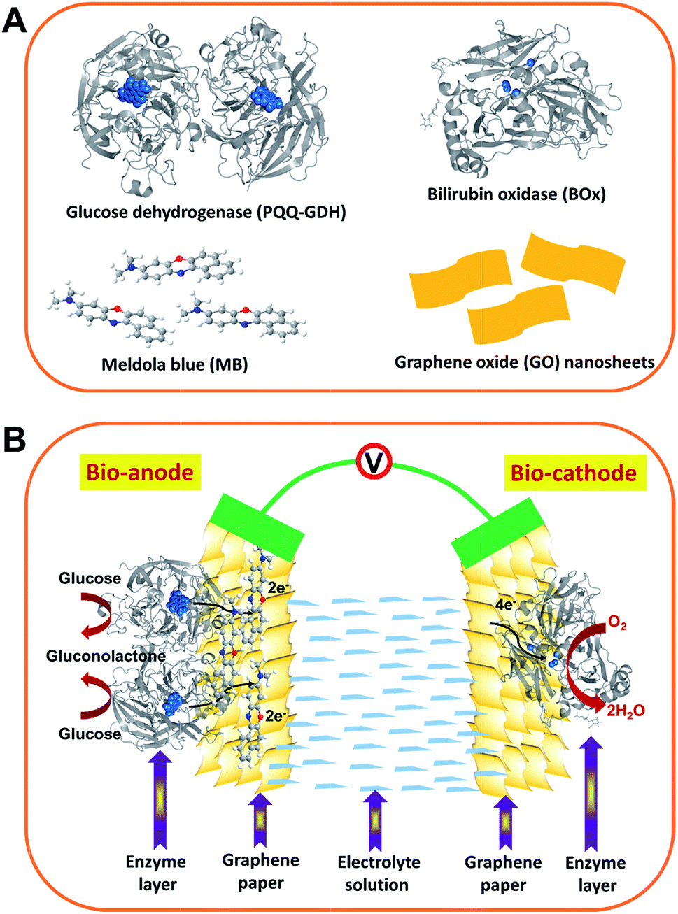 | ||
| Scheme 1 Schematic illustration of (A) the structures of the main building block materials and (B) the as-assembled enzymatic biofuel cell. Bioanode: GDH dimer with PQQ centers highlighted (PDB code 1c9u) and MB molecules were immobilized onto the graphene-paper electrode by π–π stacking. Biocathode: BOx with type I and type II/III (copper centers) marked (PDB code 2xll) directly adsorbed onto the graphene-paper electrode. Not drawn to scale. | ||
Experimental section
Chemicals and enzymes
Meldola blue (MB), i.e. 8-dimethylamino-2,3-benzophenoxazine hemi(zinc chloride) salt (>90%), 1,4-piperazinediethanesulfonic acid (PIPES) (99.5%), D-(+)-glucose (99.5%), uric acid sodium salt and sodium L-ascorbate (>98%) were from Sigma, and potassium dihydrogen phosphate (99.995%) and dipotassium phosphate (99.995%) from Fluka. Sodium hydroxide (99.99%), calcium chloride dihydrate (99%), sodium L-lactate (>99.0%), hydrazine hydrate, bovine serum albumin (BAS) and Bradford reagent were from Sigma-Aldrich. Potassium hexacyanoferrate(III) (99%) was from Riedel-de Haën. GO powder was either in-house prepared21 or obtained from the Sixth Element Inc. PQQ-GDH (1020 U mg−1) from Acinetobacter calcoaceticus was purchased from Sorachim SA. BOx from Myrothecium verrucaria (167 U mg−1) was produced and purified by Novozymes A/S based on a previously reported protocol.32 All chemicals were used as received without further purification. Milli-Q water (18.2 MΩ cm) was used throughout.Graphene paper preparation
Synthesis of the graphene paper was based on previously reported procedures18,23,33 but with modification regarding particularly conductivity improvement (vide infra), which is crucial for the freestanding bioelectrode acting simultaneously as a current collector. First, GO powder was dispersed in Milli-Q water and sonicated for 2 h below 30 °C to obtain a 1 mg mL−1 GO dispersion. Then 20 mL of GO dispersion was vacuum filtered through a membrane with an average pore size of 0.2 μm and a diameter of 47 mm. After peeling off from the filter membrane, freestanding GO paper was obtained. The transformation of the GO paper to rGO paper was achieved by placing GO paper in a Teflon container together with a tiny beaker containing 100 μL of hydrazine but no direct contact with the hydrazine solution.33 The container was sealed in a stainless steel autoclave and heated to 99 °C for 2 h. Upon elevating the temperature, hydrazine evaporated to form a steam filling the whole container, and reducing the GO paper to rGO paper. Finally, to remove residual hydrazine and further enhance the conductivity, the rGO paper was annealed at 600 °C for 1 h in a high-temperature oven under Ar flow. For facilitating electrochemical measurements, the graphene paper was cut to rectangular pieces (typically 0.5 cm × 1 cm) with an effective geometric surface area of 0.25 cm2.Morphology, surface resistance and elemental composition of graphene paper
The morphology of the dispersed GO was probed by tapping mode atomic force microscopy (AFM, Agilent) with a Tap300Al-G tip from Budget Sensors. The topography of the GO and rGO paper was further characterized by scanning electron microscopy (SEM) using a Quanta FEG 200 ESEM electron microscope from FEI with TX microscope Control Software. The surface resistance of the graphene paper was characterized using a four-point probe (FPP) from a Jandel Model RM3 test station. The elemental composition of the GO paper and rGO paper before and after annealing was analyzed by X-ray photoelectron spectroscopy (XPS) using a Thermo Scientific XPS System with the operating and data analyzing software Advantage.Bioanode preparation
Bioanodes were fabricated by physical adsorption of PQQ-GDH onto as-prepared 2D-GP electrodes. For the immobilization of the MB mediator, the 2D-GP electrode was immersed in a 10 mM MB aqueous solution and left overnight. The MB modified 2D-GP electrode was then rinsed with Milli-Q water at least three times to remove unbound MB. PQQ-GDH solution in a 20 mM PIPES buffer (pH 7.0 adjusted with NaOH solution) containing 3 mM CaCl2 as the stabilizer was prepared. 10 μL of a 4 mg mL−1 PQQ-GDH solution was drop-cast onto the MB modified 2D-GP electrode and then kept in a moisture chamber at 4 °C for 30 min. Before use, the bioanode was rinsed copiously with phosphate buffer.Biocathode preparation
The enzyme immobilization procedure for biocathodes was similar to that for the bioanodes but without mediators. 10 μL of a 3.61 mg mL−1 BOx solution (in 20 mM Tris buffer, containing 100 mM Na2SO4, pH 8.0) was spread on the 2D-GP electrode surface and kept in a moisture chamber at 4 °C for 30–40 min. After enzyme adsorption, the electrodes were rinsed with buffer solution to remove the loosely bound enzyme.Immobilized enzyme concentration tests
The enzyme concentration was tested according to the Bradford protein assay.34,35 A standard curve was prepared by testing the absorbance (595 nm) of various concentrations of BSA (50 μL) mixed with Bradford reagent (1.5 mL). The amount of immobilized enzyme on the 2D-GP electrodes was calculated from the difference between the initial and rinsed enzyme amounts.Electrochemical measurements
All electrochemical measurements were performed at room temperature (23 ± 2 °C) using a PalmSens3 electrochemical interface controlled by the PSTrace software. For half-cell tests, a three-electrode system consisting of the functionalized graphene electrodes as the working electrode, a platinum wire as the counter electrode and Ag/AgCl (KClsat) as the reference electrode was used. The EBFC performance was evaluated by using a two-electrode system with the bioanode and biocathode immersed in the same electrolyte solution without a separation membrane. The distance between the bioanode and biocathode was controlled at 1 cm. A 10 mM phosphate buffer (PB) solution at pH 7.0 was used as the electrolyte for electrochemical experiments unless stated otherwise. All presented data were obtained based on at least three independent measurements for each experiment.Results and discussion
Morphology, microscopic structures and conductivity of rGO papers
A self-supporting and flexible GO film was prepared by flow-directed assembly of GO nanosheets. AFM images show the morphology of dispersed GO and an average height of GO of about 1 nm (Fig. S1†). Assembling GO flakes formed a paper-like film, which showed a flat surface and a compact layered cross-section, Fig. 1A, C and E. However, the internal resistance of the GO film is relatively high, owing to the disruption of its sp2 bonding networks. In order to operate as a supporting electrode, the GO film must be reduced to recover high conductivity. The GO paper prepared by vacuum filtration was reduced with hydrazine vapor. Hydrazine was chosen because of its strong reducing capacity and easily removable reduction products. Water molecule layers remained in the GO layers providing channels for reductant molecules to spread into the interior of the films. Release of the gaseous products (H2O and CO2) formed during chemical reduction expanded the compact layers. The resulting rGO paper therefore possesses a rough surface and a continuously crosslinked architecture (Fig. 1D and F). The contacts between graphene sheets lower significantly the resistance of the whole rGO paper (48.33 Ω/sq). The hydrazine reduced GO paper subsequently underwent thermal annealing to remove the remaining reagents and to enhance the conductivity further. As a result, the resistance of rGO paper formed was as low as 25.86 Ω/sq. Furthermore, this rGO paper remains flexible (Fig. 1B) and surface and cross sectional structures are largely unchanged.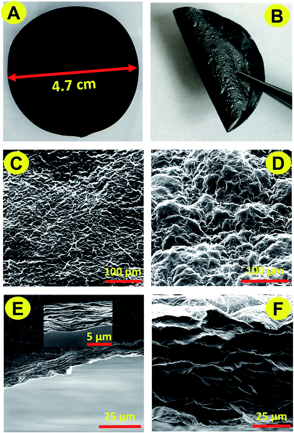 | ||
| Fig. 1 Morphology and microscopic structures of graphene papers: digital photographs of GO (A) and rGO (B) papers at the centimeter scale; SEM images of the surface structures of GO (C) and rGO (D) papers; and cross-section SEM images of the layered assembly of GO (E) and rGO (F) papers. | ||
Chemical composition of rGO papers
The elemental composition of the rGO paper during the reductive process was investigated by XPS. Fig. 2A compares the general survey spectra of the GO film, hydrazine reduced GO paper and thermally annealed rGO paper. The O1s peak intensity (around 530 eV) had significantly decreased following the hydrazine treatment, and continued to decrease after the 600 °C annealing, indicating loss of oxygen. The atomic ratios of carbon to oxygen were 2.57, 7.62 and 11.70 for the GO films before and after treatments, respectively. A new peak around 400 eV (magnified in the dashed circle) appeared after hydrazine exposure, which indicated that nitrogen was introduced. The weak intensity of this peak suggested that only a trace amount of nitrogen was incorporated, which is in accordance with reported observations.36 A slight reduction of this peak occurred after thermal treatment.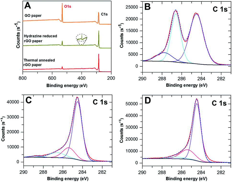 | ||
| Fig. 2 XPS of GO and rGO papers: (A) comparison of the general survey spectra of GO paper, hydrazine reduced GO paper and thermally annealed GO paper. (B–D) Corresponding C1s spectra, respectively analyzed in detail; the solid red curves are the measured data, and the dashed blue curves are the overall fitting. The curves in other colors are deconvoluted spectra. | ||
The detailed C1s spectra of the graphene papers before and after treatments are shown in Fig. 2B–D, respectively, along with the curve fitting using the Thermo Advantage software with a fixed Gaussian/Lorentzian (G/L) ratio. The untreated GO paper had a main peak at 284.5 eV (53.48%) assigned to the aromatic sp2 structures, and another broad peak with a tail towards higher binding energy attributed to the overlap of various carbon bonding configurations. The second peak can be assigned to C–O single bonds at 286.6 eV (35.83%) and carbon doubly bonded to oxygen at 287.8 eV (10.69%).28 After chemical treatment, the fraction of carbon contributing to C–O and C![[double bond, length as m-dash]](https://www.rsc.org/images/entities/char_e001.gif) O bonds had decreased significantly to 10.57% and 2.11%, respectively. Conversely, the main peak at 284.5 eV had increased to 70.42% and a new component at 258.4 eV (16.90%) corresponding to the C–C single bond28 appeared. The change of various carbon functional groups retained the previous tendency but slowed down after thermal treatment, indicative of further reduction of GO. A small percentage of C–O groups was still present (4.41%), but the CO peak had completely disappeared, whereas the CC and C–C group signals had increased slightly, to 73.53% and 22.06%, respectively. These results support the observed recovery of conductivity of the 2D-GP electrodes.
O bonds had decreased significantly to 10.57% and 2.11%, respectively. Conversely, the main peak at 284.5 eV had increased to 70.42% and a new component at 258.4 eV (16.90%) corresponding to the C–C single bond28 appeared. The change of various carbon functional groups retained the previous tendency but slowed down after thermal treatment, indicative of further reduction of GO. A small percentage of C–O groups was still present (4.41%), but the CO peak had completely disappeared, whereas the CC and C–C group signals had increased slightly, to 73.53% and 22.06%, respectively. These results support the observed recovery of conductivity of the 2D-GP electrodes.
Electrochemical behavior of MB modified rGO papers
Before any modification, the bare 2D-GP electrode was characterized electrochemically in the presence of the electroactive species K3[Fe(CN)6] at different scan rates. As shown in Fig. S2,† well-defined redox peaks at E1/2 = 0.23 V vs. Ag/AgCl, KClsat were observed. The peak current follows closely a square root dependence of scan rate, which is in accordance with diffusion control. The 2D-GP electrodes with MB molecules adsorbed via noncovalent bonding were investigated next (Fig. S3A†). As a phenoxazinium salt, MB contains several aromatic rings, and can adsorb onto carbon materials by π–π stacking. Cyclic voltammograms (CVs) of the MB modified graphene electrode are shown in Fig. S3B.† Well-defined two-electron redox peaks at E1/2 = −0.15 V, eqn (1) were observed, caused by reversible oxidation/reduction of the two nitrogenic moieties (Fig. S3C†). The peak current retained the same intensity after 20 scans, verifying stable MB adsorption on the electrodes.| MB+ + H+ + 2e− ↔ MBH | (1) |
Ideally, the anodic and cathodic peaks should be symmetric. However, peak separation remained right down to 53 mV at 0.1 V s−1 probably due to the rough surface of the graphene electrodes, and diffusing protons. Although there should be no mass transport constraints of oxidized and reduced reactants since both are present on the electrode surface, protons involved in the redox reaction (eqn (1)) still have to be exchanged with the electrolyte. This could give rise to peak separation, e.g. due to a concentration gradient.37,38 The surface coverage of MB, ΓMB, could be determined from the CVs according to the Laviron equation:39
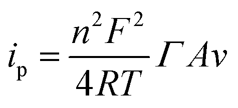 | (2) |
CVs of MB modified electrodes with different scan rates (e.g., 0.005–0.5 V s−1) showed a linear relationship between ip and v (up to 0.4 V s−1), Fig. S4,† which is in accordance with diffusion-less voltammetry, but the ip/v correlation begins to deviate from linearity at higher scan rates. This could result from similar “non-ideality” to that for the observed peak separation, such as rough surface, fast scan rate and proton transport. The standard apparent interfacial electrochemical electron transfer rate constant (kapp) of MB was again calculated by Laviron's method40 using the following equations:
 | (3) |
 | (4) |
Electrocatalytic oxidation of glucose at the 2D-GP bioanode
PQQ-GDH was physically adsorbed onto the MB modified electrode (anode) and then employed as the biocatalyst for glucose oxidation at the anode. The amount of immobilized PQQ-GDH on the electrode was determined to be around 4.78 × 10⁻¹⁰ mol cm−2. MB has been widely used as a mediator for NADH or NADPH based dehydrogenases due to its fairly low redox potential and photo-insensitivity.37,41 Here, we show that physically adsorbed MB can establish an electron transfer pathway between the redox center of PQQ-GDH and the graphene paper. Fig. 3A displays the sigmoidal bioelectrocatalytic curves in the presence of glucose. The biocatalytic current starts from a potential of about −0.15 ± 0.02 V and rises to a limiting value around 0.05 V. The onset potential towards glucose achieved herein is close to those of most PQQ-GDH bioelectrodes,16,42–45 and even 0.33 V lower compared to that of mediator-free PQQ-GDH linked to carbon fiber electrodes functionalized with graphene nanosheets,46 testifying to robust and competitive operation of the new graphene paper bioanode. Control experiments without enzyme showed no catalytic signals in this potential range (Fig. S6†), verifying that the glucose oxidation resulted from PQQ-GDH. The catalytic current of the as-prepared bioanode increases with increasing concentrations of glucose (Fig. S7†). When the concentration of glucose reaches 5 mM, the enzyme response towards glucose is close to the saturation value. It is worth noting that this glucose concentration is well matched with the average value of glucose in human blood,47 indicating the potential for implantable application. The catalytic processes can be described by the following equations:| PQQ-GDH + D-glucose → PQQH2-GDH + D-glucono-1,5-lactone | (5) |
| PQQH2-GDH + MB+ → PQQ-GDH + MBH + H+ | (6) |
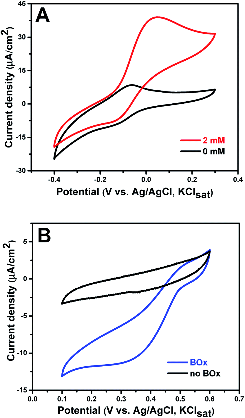 | ||
| Fig. 3 Electrocatalytic reactions at the bioanode and biocathode: (A) CVs obtained for the PQQ-GDH anode with and without glucose in air saturated PB; (B) CVs at bare GP and the BOx cathode in air-saturated PB. Scan rate: 5 mV s−1. | ||
PQQ-GDH oxidizes dextroglucose to gluconolactone and is itself reduced to PQQH2-GDH, which then transfers electrons to MB+ (the oxidized form of MB) to recover its catalytic ability. The MBH formation (the reduced form of MB) was followed by electrooxidation on the electrode, eqn (1). The low catalytic potential of this bioanode towards glucose oxidation is very attractive for EBFCs.
Electrocatalytic reduction of dioxygen at the 2D-GP biocathode
The multicopper oxidase, BOx, was chosen as the biocatalyst for the dioxygen reduction reaction (ORR) at the cathode without using mediators. The biocathode was again fabricated by facile direct adsorption of the enzyme onto the bare 2D-GP electrode. The amount of immobilized BOx on the electrode was approximately 3.02 × 10⁻¹⁰ mol cm−2. The reduction current of the BOx biocathode in air-saturated PB was recorded by cyclic voltammetry (Fig. 3B). The reduction reaction started around 0.50 ± 0.02 V and reached a limiting current density of 11.78 μA cm−2 at 0.20 V, which is similar to the reported results for BOx immobilized on other carbon electrodes.48 No reduction on the bare graphene electrode between 0.1 and 0.6 V was observed, confirming that dioxygen reduction was in fact catalyzed by BOx. Since no mediator was introduced in this system, dioxygen reduction was effected by direct ET between the enzyme and graphene paper, as described by eqn (7) and (8).| BOxox + 4e− → BOxred | (7) |
| BOxred + O2 + 4H+ → BOxox + 2H2O | (8) |
In the detailed catalytic mechanism, four electrons sequentially tunnel from the electrode to the fully oxidized enzyme. The four electrons are transferred via the type I copper center of BOx. One electron is left at the type I center and three electrons are transferred further to the type II/III center by intramolecular ET, forming the fully reduced enzyme.49 Subsequently, O2 reacts with the reduced trinuclear copper center forming a peroxy intermediate (PI), in which two copper ions are oxidized. A second intramolecular two-electron transfer step then occurs along with the cleavage of the O–O bond in the PI, resulting in a fully oxidized intermediate enzyme form (NI).50 With electrons from the electrode and protons from the electrolyte, the fully oxidized NI is rapidly reduced to the fully reduced form of BOx along with liberation of water. Efficient electron tunneling between the electrode and T1 site of BOx requires a short surface-type I distance and an appropriate orientation of the enzyme.51 The rough surface of the graphene electrode seemingly provides such appropriate biocompatible binding sites and short BOx ET distances, leading to an effective biocathode with DET towards the ORR.
Electrochemical performance of as-constructed EBFCs
The prepared new graphene paper based PQQ-GDH bioanode and BOx biocathode were assembled into a complete EBFC. The performance of this biofuel cell was investigated by linear sweep voltammetry (LSV) in air-saturated PB containing 6.4 mM glucose (Fig. 4A). Glucose was oxidized at the anode and donated electrons, which traveled through the external circuit to the cathode and were subsequently accepted by O2. As shown in the individual polarization curves of the bioanode and biocathode, the anodic catalytic current was around twice higher than that for the cathode, indicating that the EBFC performance is mainly limited by the activity of the cathode (Fig. S8†). The open circuit voltage (OCV) of the assembled EBFC was ca. 0.665 V, which is similar to those of other reported PQQ-GDH/MCOs EBFCs16,43 operating in PB, and 0.255 V higher than that of the graphene functionalized EBFC.46 A maximum power density of 4.03 μW cm−2 was obtained at a voltage of 0.42 V, which is significantly higher compared to that of a recently reported EBFC based on spectrographic graphite as the electrode support.6Table 1 compares the performance of graphene material based bioelectrochemical systems with different kinds of biocatalysts. The peak power output in the present work is comparable with the recently reported results.46,52,53 Other reports show a 5–7 times higher power density than that achieved in this work, but with consumption of a much higher concentration of glucose, which is far beyond the glucose concentration in normal human blood. The stability of the new EBFC was further tested by continually recording the current at the potential with the maximum power density and found to be comparable with that of a recently reported mediated EBFC with the highest performance ever achieved for whole human blood (Fig. S9†).16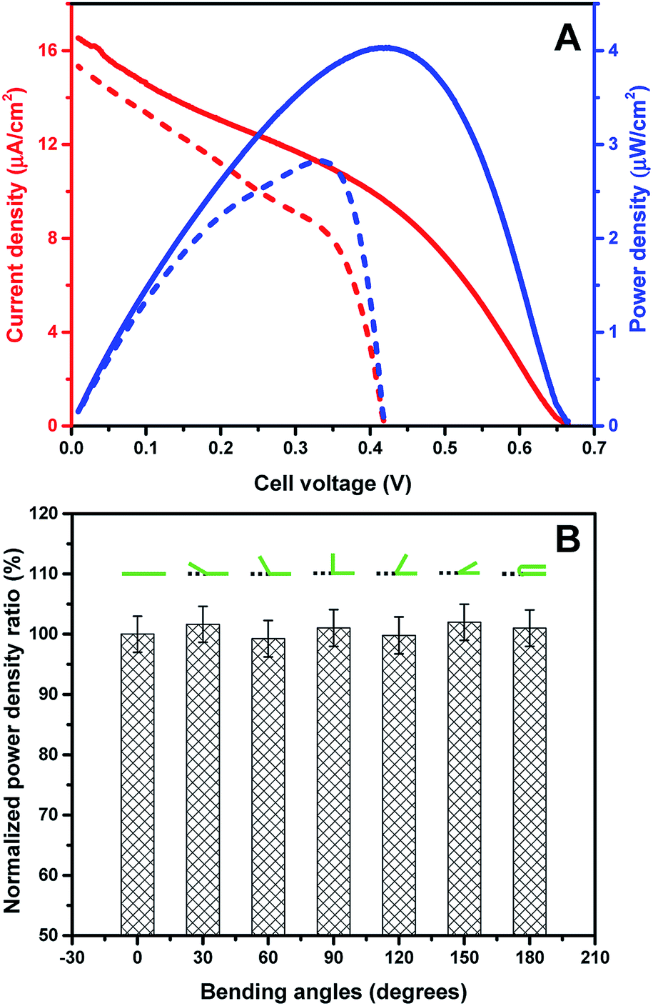 | ||
| Fig. 4 (A) Representative polarization curve (red) and power curve (blue) obtained from the GDH bioanode and BOx biocathode in air-saturated buffer containing 6.4 mM glucose. Solid and dashed curves are recorded for pure PB buffer and BMB buffer, respectively. Scan rate 1 mV s−1. (B) Power density ratio of EBFCs after bending to various angles. | ||
| Anodic enzyme | Fuel concentration | Cathodic enzyme | Electrode architecture | OCV (V) | Power density (μW cm−2) | Ref. |
|---|---|---|---|---|---|---|
| PQQ-GDH | 20 mM glucose | Laccase | 3D graphene nanoflakes | 0.410 | 5.50 | 46 |
| Cellobiose dehydrogenase | 5 mM glucose | Laccase | Gold nanoparticles/graphene | 0.740 | 5.16 | 52 |
| Thylakoid membranes | Light | BOx | 3D graphene matrix | 0.500 | 1.79 | 53 |
| NADH-GDH | 30 mM | Laccase | Graphene/carbon nanotubes | 0.690 | 22.5 | 57 |
| Glucose oxidase | 200 mM glucose | BOx | 3D graphene coated carbon fiber cloth | 0.620 | 34.3 | 58 |
| PQQ-GDH | 6.4 mM glucose | BOx | 2D graphene paper | 0.665 | 4.03 | This work |
To investigate the influence of mechanical deformation of the electrodes on the performance of the assembled EBFC, the power density of the EBFCs employing electrodes bent to various angles was tested. To eliminate the deviation between different electrodes, the power density of each EBFC was first recorded at the planar level (Pinitial), and then recorded at selected angles (Px°). The ratio of Px°/Pinitial was calculated and normalized for comparison. Table S1† and Fig. 4B show that the EBFC has good tolerance for bending to different angles without obvious changes in power output and internal resistance, similar to graphene–protein layer-by-layer assembled electrodes.54 The OCV and power output of the assembled EBFC are comparable with those of carbon nanotube based flexible EBFCs.55
In order to evaluate the power output of the EBFC operating in human blood, the EBFC performance was finally tested in blood mimicking buffer (BMB, pH 7.4), and was found to fully simulate the EBFC behavior in whole blood.6 BMB contained the main plasma electrolytes (including 4.05 mM K+, 141.4 mM Na+, and 105.4 mM Cl−) and redox active components (0.045 mM ascorbate, 0.425 mM). Although the OCV value in BMB expectedly dropped to 0.418 V due to parasitic reactions occurring on exposed patches of the biomodified 2D-GP, the observed decrease in OCV was only 50 mV lower compared to that of the EBFC based on the tubular spectrographic graphite,6 which indicated a more uniform enzymatic coverage of the 2D-GP surface obtained in the present work. The maximum power density achieved in BMB was 30% lower than that in the pure PB buffer (2.83 and 4.03 μW cm−2, respectively), which is still sufficient to drive a cardiac pacemaker or a self-powered biosensor.17,56
Conclusions
EBFCs based on graphene, nanotubes, and other nanoscale carbon materials have been reported and are in increasing focus. In the present study, we have introduced a novel graphene-based EBFC that offers several merits compared with reported related systems. First, the electrode material is freestanding graphene paper – as opposed to carbon or gold supported graphene electrode materials prepared by optimized chemical synthesis. Being of paper design, the mechanically flexible, freestanding, and low-cost graphene electrodes hold favorable properties regarding implantation in a biological environment. Secondly, the graphene electrode material was characterized comprehensively by SEM, XPS, AFM and four-point conductivity ascertaining that optimal conductivity and other physical properties are achieved. Thirdly, the bioanode and biocathode are based on PQQ-GDH and BOx, respectively and can be prepared by facile direct physical adsorption on the new flexible graphene paper electrodes.The electrochemical and electrocatalytic properties of the new PQQ-GDH bioanode and BOx biocathode were tested comprehensively by cyclic voltammetry and found to display robust monolayer voltammetry and efficient electrocatalysis towards glucose oxidation and dioxygen reduction. PQQ-GDH needs the MB mediator for facile electrocatalysis, whereas direct electron transfer between the enzyme and graphene paper electrode could be effected for the BOx biocathode. The EBFCs were tested particularly for solutions that mimic real blood samples.
The new electrodes were finally used to design and build a working EBFC, the merits of which are membrane-less construction, mechanical flexibility, biocompatibility, low cost, and facile engineering. The peak power output and stability are broadly comparable with reported results for other carbon based EBFCs and must be improved to meet the demands for practical application. The lack of significantly improved fuel cell performance must, however, be weighed up against the facile electrode and bioelectrode preparation, and the meritorious mechanically flexible structure of the free-standing graphene paper electrodes. Bending was found not to compromise the core electronic properties of the electrodes such as conductivity in particular. The latter offers perspectives for implantable or wearable application, where the power output of the developed EBFCs holds the potential to drive low-power biomedical and bioanalytical microelectronics. Reducing the power requirement of portable medical devices will be an issue of their future development. Further performance enhancement of biocathodes, which seems to be the limiting factor in efficient performance, and long-term stability of EBFCs could therefore be the focus for ongoing efforts.
Conflicts of interest
There are no conflicts to declare.Acknowledgements
J. Z. acknowledges the Danish Council for Independent Research under the YDUN project (DFF 4093-00297). Q. C. thanks the Danish Council for Independent Research for Technology and Product Sciences (DFF-FTP, Project No. 12-127447). F. S. acknowledges the PhD scholarship from the China Scholarship Council (CSC 201506170059). D. P. is grateful for an Ørsted-Marie-Curie Cofunded postdoc fellowship. L. G. acknowledges the European Commission (“Bioenergy” PEOPLE-2013-ITN-607793) and the Swedish Research Council (Project No. 2014-5908). JU acknowledges financial support from the Russian Science Foundation (17-13-01274). We acknowledge Dr Sophie Beeren and PhD student Xiaomei Yan help us correct the structure of reduced Meldola blue and the figure of π–π staking interaction between Meldola blue and graphene in the supporting information.References
- S. Cosnier, A. Le Goff and M. Holzinger, Electrochem. Commun., 2014, 38, 19–23 CrossRef CAS.
- S. Shleev, ChemPlusChem, 2017, 82, 522–539 CrossRef CAS.
- S. Cosnier, A. J. Gross, F. Giroud and M. Holzinger, Curr. Opin. Electrochem., 2018, 12, 148–155 CrossRef CAS.
- S. Cosnier, A. Le Goff and M. Holzinger, in Implantable Bioelectronics, Wiley-VCH Verlag GmbH & Co. KGaA, Weinheim, Germany, 2014, pp. 347–362 Search PubMed.
- M. Rasmussen, S. Abdellaoui and S. D. Minteer, Biosens. Bioelectron., 2016, 76, 91–102 CrossRef CAS PubMed.
- D. Pankratov, L. Ohlsson, P. Gudmundsson, S. Halak, L. Ljunggren, Z. Blum and S. Shleev, RSC Adv., 2016, 6, 70215–70220 RSC.
- A. Dector, R. A. Escalona-Villalpando, D. Dector, V. Vallejo-Becerra, A. U. Chávez-Ramírez, L. G. Arriaga and J. Ledesma-García, J. Power Sources, 2015, 288, 70–75 CrossRef CAS.
- C. H. Kwon, J. A. Lee, Y. B. Choi, H. H. Kim, G. M. Spinks, M. D. Lima, R. H. Baughman and S. J. Kim, J. Power Sources, 2015, 286, 103–108 CrossRef CAS.
- P. Ó Conghaile, M. Falk, D. MacAodha, M. E. Yakovleva, C. Gonaus, C. K. Peterbauer, L. Gorton, S. Shleev and D. Leech, Anal. Chem., 2016, 88, 2156–2163 CrossRef PubMed.
- M. Southcott, K. MacVittie, J. Halámek, L. Halámková, W. D. Jemison, R. Lobel and E. Katz, Phys. Chem. Chem. Phys., 2013, 15, 6278–6283 RSC.
- A. Zebda, S. Cosnier, J. P. Alcaraz, M. Holzinger, A. Le Goff, C. Gondran, F. Boucher, F. Giroud, K. Gorgy, H. Lamraoui and P. Cinquin, Sci. Rep., 2013, 3, 1516 CrossRef CAS PubMed.
- J. A. Castorena-Gonzalez, C. Foote, K. MacVittie, J. Halámek, L. Halámková, L. A. Martinez-Lemus and E. Katz, Electroanalysis, 2013, 25, 1579–1584 CrossRef CAS.
- I. Mazurenko, A. de Poulpiquet and E. Lojou, Curr. Opin. Electrochem., 2017, 5, 74–84 CrossRef CAS.
- P. Mishra, G. B. V. S. Lakshmi, S. Mishra, D. K. Avasthi, H. C. Swart, A. P. F. Turner, Y. K. Mishra and A. Tiwari, Nano Energy, 2017, 39, 601–607 CrossRef CAS.
- M. Gamella, A. Koushanpour and E. Katz, Bioelectrochemistry, 2018, 119, 33–42 CrossRef CAS PubMed.
- M. Cadet, S. Gounel, C. Stines-Chaumeil, X. Brilland, J. Rouhana, F. Louerat and N. Mano, Biosens. Bioelectron., 2016, 83, 60–67 CrossRef CAS PubMed.
- C.-Y. Tsui, Found. Trends® Electron. Des. Autom., 2013, 7, 179–246 CrossRef.
- M. Zhang, A. Halder, C. Hou, J. Ulstrup and Q. Chi, Bioelectrochemistry, 2016, 109, 87–94 CrossRef CAS PubMed.
- M. Zhang, A. Halder, X. Cao, C. Hou and Q. Chi, in Electrochemical Sensors Technology, InTechOpen, London, UK, 2017, pp. 33–62 Search PubMed.
- N. Zhu, S. Han, S. Gan, J. Ulstrup and Q. Chi, Adv. Funct. Mater., 2013, 23, 5297–5306 CrossRef CAS.
- A. Halder, M. Zhang and Q. Chi, Biosens. Bioelectron., 2017, 87, 764–771 CrossRef CAS PubMed.
- N. Aryal, A. Halder, P. L. Tremblay, Q. Chi and T. Zhang, Electrochim. Acta, 2016, 217, 117–122 CrossRef CAS.
- N. Aryal, A. Halder, M. Zhang, P. R. Whelan, P. L. Tremblay, Q. Chi and T. Zhang, Sci. Rep., 2017, 7, 9107 CrossRef PubMed.
- M. Zhang, C. Hou, A. Halder, H. Wang and Q. Chi, Mater. Chem. Front., 2017, 1, 37–60 RSC.
- C. Hou, M. Zhang, A. Halder and Q. Chi, Electrochim. Acta, 2017, 242, 202–218 CrossRef CAS.
- D. R. Dreyer, S. Park, C. W. Bielawski and R. S. Ruoff, Chem. Soc. Rev., 2010, 39, 228–240 RSC.
- R. Jalili, A. Kanneganti, M. I. Romero-Ortega and G. G. Wallace, Curr. Opin. Electrochem., 2017, 3, 68–74 CrossRef CAS.
- C. Di Bari, A. Goñi-Urtiaga, M. Pita, S. Shleev, M. D. Toscano, R. Sainz and A. L. De Lacey, Electrochim. Acta, 2016, 191, 500–509 CrossRef CAS.
- S. H. Inamuddin and M. Naushad, Enzyme Microb. Technol., 2016, 87–88, 29–36 CrossRef PubMed.
- P. P. Gai, C. E. Zhao, Y. Wang, E. S. Abdel-Halim, J. R. Zhang and J. J. Zhu, Biosens. Bioelectron., 2014, 62, 170–176 CrossRef CAS PubMed.
- C. Liu, S. Alwarappan, Z. Chen, X. Kong and C. Z. Li, Biosens. Bioelectron., 2010, 25, 1829–1833 CrossRef CAS PubMed.
- M. Falk, V. Andoralov, M. Silow, M. D. Toscano and S. Shleev, Anal. Chem., 2013, 85, 6342–6348 CrossRef CAS PubMed.
- Z. Niu, J. Chen, H. H. Hng, J. Ma and X. Chen, Adv. Mater., 2012, 24, 4144–4150 CrossRef CAS PubMed.
- M. M. Bradford, Anal. Biochem., 1976, 72, 248–254 CrossRef CAS PubMed.
- X. Xiao, T. Siepenkoetter, R. Whelan, U. Salaj-Kosla and E. Magner, J. Electroanal. Chem., 2018, 812, 180–185 CrossRef CAS.
- D. Yang, A. Velamakanni, G. Bozoklu, S. Park, M. Stoller, R. D. Piner, S. Stankovich, I. Jung, D. A. Field, C. A. Ventrice and R. S. Ruoff, Carbon, 2009, 47, 145–152 CrossRef CAS.
- L. Gorton, A. Torstensson, H. Jaegfeldt and G. Johansson, J. Electroanal. Chem., 1984, 161, 103–120 CrossRef CAS.
- K. N. Isao Taniguchi, T. Shimoota and M. Tominaga, Microchem. J., 1994, 49, 340–354 CrossRef.
- E. Laviron, J. Electroanal. Chem., 1974, 52, 395–402 CrossRef CAS.
- P. S. Jensen, Q. Chi, F. B. Grumsen, J. M. Abad, A. Horsewell, D. J. Schiffrin and J. Ulstrup, J. Phys. Chem. C, 2007, 111, 6124–6132 CrossRef CAS.
- A. Koushanpour, M. Gamella, N. Guz and E. Katz, Electroanalysis, 2017, 29, 950–954 CrossRef CAS.
- D. Sarauli, K. Peters, C. Xu, B. Schulz, D. Fattakhova-Rohlfing and F. Lisdat, ACS Appl. Mater. Interfaces, 2014, 6, 17887–17893 CrossRef CAS PubMed.
- P. Pinyou, A. Ruff, S. Pöller, S. Ma, R. Ludwig and W. Schuhmann, Chem.–Eur. J., 2016, 22, 5319–5326 CrossRef CAS PubMed.
- Y. Nakashima, N. Mizoshita, H. Tanaka and Y. Nakaoki, Langmuir, 2016, 32, 12986–12994 CrossRef CAS PubMed.
- G. Fusco, G. Göbel, R. Zanoni, M. P. Bracciale, G. Favero, F. Mazzei and F. Lisdat, Biosens. Bioelectron., 2018, 112, 8–17 CrossRef CAS.
- A. Koushanpour, N. Guz, M. Gamella and E. Katz, ECS J. Solid State Sci. Technol., 2016, 5, 3037–3040 CrossRef.
- B. P. Kovatchev, E. Otto, D. Cox, L. Gonder-Frederick and W. Clarke, Diabetes Care, 2006, 29, 2433–2438 CrossRef CAS.
- F. Giroud, K. Sawada, M. Taya and S. Cosnier, Biosens. Bioelectron., 2017, 87, 957–963 CrossRef CAS PubMed.
- V. Climent, J. Zhang, E. P. Friis, L. H. Østergaard and J. Ulstrup, J. Phys. Chem. C, 2012, 116, 1232–1243 CrossRef CAS.
- E. I. Solomon, R. Sarangi, J. S. Woertink and A. J. Augustine, Acc. Chem. Res., 2007, 40, 581–591 CrossRef CAS PubMed.
- C. Gutiérrez-Sánchez, M. Pita, C. Vaz-Domínguez, S. Shleev and A. L. De Lacey, J. Am. Chem. Soc., 2012, 134, 17212–17220 CrossRef PubMed.
- P. Bollella, G. Fusco, D. Stevar, L. Gorton, R. Ludwig, S. Ma, H. Boer, A. Koivula, C. Tortolini, G. Favero, R. Antiochia and F. Mazzei, Sens. Actuators, B, 2018, 256, 921–930 CrossRef CAS.
- G. Pankratova, D. Pankratov, C. Di Bari, A. Goñi-Urtiaga, M. D. Toscano, Q. Chi, M. Pita, L. Gorton and A. L. De Lacey, ACS Appl. Energy Mater., 2018, 1, 319–323 CrossRef CAS.
- I. M. Mosa, A. Pattammattel, K. Kadimisetty, P. Pande, M. F. El-Kady, G. W. Bishop, M. Novak, R. B. Kaner, A. K. Basu, C. V. Kumar and J. F. Rusling, Adv. Energy Mater., 2017, 7, 1700358 CrossRef PubMed.
- X. E. Wu, Y. Z. Guo, M. Y. Chen and X. D. Chen, Electrochim. Acta, 2013, 98, 20–24 CrossRef CAS.
- E. Katz, A. F. Bückmann and I. Willner, J. Am. Chem. Soc., 2001, 123, 10752–10753 CrossRef CAS.
- X. Wang, J. Wang, H. Cheng, P. Yu, J. Ye and L. Mao, Langmuir, 2011, 27, 11180–11186 CrossRef CAS PubMed.
- K. Hoshi, K. Muramatsu, H. Sumi and Y. Nishioka, Jpn. J. Appl. Phys., 2016, 55, 02BE05 CrossRef.
Footnote |
| † Electronic supplementary information (ESI) available: Supporting data presented in nine figures and one table. See DOI: 10.1039/c9na00178f |
| This journal is © The Royal Society of Chemistry 2019 |