
 Open Access Article
 This Open Access Article is licensed under a Creative Commons Attribution-Non Commercial 3.0 Unported Licence
Stretchable elastomer composites with segregated filler networks: effect of carbon nanofiller dimensionality†
Kai
Ke
 *,
Zhen
Sang
and
Ica
Manas-Zloczower
*
*,
Zhen
Sang
and
Ica
Manas-Zloczower
*
Department of Macromolecular Science and Engineering, Case Western Reserve University, 2100 Adelbert Road, Cleveland, OH 44106-7202, USA. E-mail: kxk424@case.edu; ixm@case.edu
First published on 8th May 2019
Abstract
Electrically conductive elastomer composites (CECs) have great potential in wearable and stretchable electronic applications. However, it is often challenging to trade off electrical conductivity and mechanical flexibility in melt-processed CECs for wearable electronic applications. Here, we develop CECs with high electrical conductivity and mechanical elasticity by controlling the segregated networks of carbon nanofillers formed at the elastomer interface. The carbon nanofiller dimensionality has a significant influence on the electrical and mechanical properties of thermoplastic polyurethane (TPU) composites. For instance, 3D branched carbon nanotubes (carbon nanostructures, CNSs) have a very low percolation threshold (ΦC = 0.01 wt%), which is about 8–10 times lower than that of 1D carbon nanotubes (CNTs) and 2D graphene nanosheets (GNSs). Besides, the TPU/CNS system has a higher electrical conductivity than other fillers at all filler contents (0.05–2 wt%). On the other hand, TPU/CNT systems can retain high elongation at break, whereas for the TPU/GNS systems elongation at break is severely deteriorated, especially at a high filler content. Different electrical and mechanical properties in the TPU-based CECs enable potential applications in flexible conductors/resistors and stretchable strain sensors, respectively.
1. Introduction
The rise of the Internet of Things makes the development of flexible electronic materials of great demand for human–machine interface bridging. As the human skin is compliant to any curved structure, lightweight conductive elastomer composites (CECs) with excellent flexibility and stretchability are very good alternatives to conventional metal-based conductive materials for wearable electronics. Currently, CECs have been widely used in stretchable conductors,1–8 wearable strain sensors,9–19 and flexible pressure sensors.20–27As elastomers are intrinsically insulating, it is essential to incorporate conductive materials into elastomers for the fabrication of CECs. There are three main reported strategies: (1) infiltrating elastomers with conductive filler networks,9,10,28,29 (2) synthesizing metal fillers within elastomers3,28,30–32 and (3) implanting conductive fillers into elastomers.12,21,22,26,27,33–45 The first strategy generally requires particular fabrication techniques, such as surface treatment, to assist the combination of elastomers with conductive fillers. Besides, conductive filler networks built on the surface or in the subsurface of the elastomers may be damaged under long-term high-level strain service duration due to the weak bonding between filler networks and elastomers. Synthesizing metal fillers within elastomers is an effective method to combine elastomers and conductive fillers by forming uniform filler networks in elastomers. However, it is only suitable for incorporating metal nanoparticles into elastomers, and the elastomer solution or latex is a prerequisite for the dispersion and reduction reaction of metal precursors. As such, implanting conductive fillers into elastomers by either solution or melt mixing, is relatively low-cost and facile, and thus widely reported in the literature. Nevertheless, the electrical conductivity depends on the percolation behavior of conductive fillers dispersed in the elastomers and the composites become electrically conductive only if the filler content reaches a critical content, i.e. percolation threshold (ΦC). In comparison with solution and melt mixing, the formation of segregated filler networks at the polymer interface is a more efficient strategy to reduce ΦC and to achieve good electrical conductivity for polymer composites.38,46–54 In this strategy, conductive fillers are trapped at the interface of polymer particles in contact with each other, leading to economic and efficient formation of conductive paths along the polymer–polymer interface. However, due to the weak polymer–filler interfacial interactions and bad filler distribution at the interface, the resultant composites usually have deteriorated elongation at break when compared with those fabricated via solution/melt mixing, especially at high filler loading.51,54–56 As such, these composites have high potential for electromagnetic interference shielding52,54 and thermoelectric applications,51,57–59 which focus more on electrical conductivity. However, the fabrication of stretchable electronics often requires both high electrical conductivity and high stretchability. It is challenging to realize this in segregated CECs by using common carbon nanofillers at low filler loading.
Recently, graphene foam (three-dimensional, 3D) has become an attractive alternative to common carbon nanofillers for the fabrication of conductive polymer composites due to their excellent conductivity.16,60–64 Likewise, branched carbon nanotubes (CNSs) (3D) are superior to multi-walled carbon nanotubes (CNTs) (1D) or graphene nanoplatelets (2D) for improving the electrical conductivity of melt-mixed polymer composites,34,65 in alignment with theoretical studies.66 However, for segregated network structures, the literature suggests that carbon nanofillers with lower dimensionality tend to have lower ΦC values and higher electrical conductivity at the same filler loading in thermoplastic nanocomposites.49,67 The rationale for this observation is the agglomeration of 2D graphene caused by filler stacking as well as the plane-to-plane contact in comparison with the end-to-end contact for 1D CNTs. In addition, the resultant composites often have severely deteriorated elongation at break. Therefore, exploration of effective strategies to improve filler dispersion and to enhance the filler–polymer interface is crucial for simultaneously achieving high elongation at break and electrical conductivity in the CECs.
In our previous work, it was found that the formation of segregated CNS networks at the interface of thermoplastic polyurethane (TPU), which is a widely used elastomer for flexible sensors,17,25,39,42,44,68,69 is able to significantly reduce ΦC of the TPU/CNS composites in comparison with melt mixing.70 Besides, the elastomer particle size plays an important role in controlling the filler network morphology in the segregated network structure, affecting the composite's electrical and mechanical properties.71 Another key factor affecting the polymer nanocomposite's electrical and mechanical properties significantly is nanofiller dimensionality.72 This factor has not been studied so far in CEC systems with segregated networks for piezoresistive sensing applications.
In this study we developed thermoplastic polyurethane composites with different carbon nanofillers (1D CNTs, 2D GNSs and 3D CNSs) using the brick-wall structure strategy, i.e. forming segregated filler networks at the elastomer interface. We aim to obtain elastomer composites with high electrical conductivity (>1 S m−1) and large elongation at break (>1000%) simultaneously to ensure stretchable and wearable electronic applications. The morphology, electrical and mechanical properties, as well as piezoresistive behaviors of the composites with the three types of carbon nanofillers were comparatively studied. Moreover, potential applications of these stretchable TPU-based CECs for piezoresistive strain sensors and resistors were demonstrated.
2. Experimental
2.1 Materials and composite preparation
Commercial TPU consisting of p-phenylenediisocyanates and polycaprolactone polyols was used here. Carbon nanostructures CNSs (known as branched carbon nanotubes; CNS flake length 70 μm and thickness 10 μm; nanotube diameter 9 nm) were provided by Applied Nanostructured Solutions LLC (Lockheed Martin Corporation, MD, US). Multi-walled carbon nanotubes (CNTs, nanocyl NC7000, diameter 9.5 nm and length 1 μm) and single layer graphene (GNSs, Angstron N002-PDR, lateral length 10 μm and thickness 1 nm) were also used.TPU composites were prepared by grinding the TPU with an IKA grinder (MF 10) and sifting the particles to obtain a particle size of 212–300 μm. Smaller particle sizes possess more interfacial area,53 which is beneficial for the interfacial bonding between fillers and TPU, enabling good mechanical properties. Carbon nanofillers were dispersed in ethanol (ca. 40 ml) under sonication for 10 min (700 W, 45% amplitude, 5 s on and 5 s off) to achieve better dispersion (see Fig. S1 in the ESI†). The TPU powder was added into the filler suspension and mixed for 20 min under magnetic stirring at room temperature. Ultrasonication improves filler dispersion conducive to property improvement in comparison with hand mixing reported in our previous work,70 as confirmed by the results in Fig. S2 in the ESI.† The obtained mixture was dried in an oven for 36 h at 90 °C to remove residual ethanol and moisture prior to compression molding. Finally, the powdery mixture was compression molded into rectangular films (11 cm × 11 cm, 0.7 mm thick) at 230 °C under 5 MPa for 5 min. The TPU nanocomposites were labeled according to their composition, e.g. the nanocomposites with 0.7 wt% CNSs were labeled as 0.7 CNS.
2.2 Characterization
TEM images of the fillers were obtained using a FEI Tecnai F30 transmission electron microscope. The as-received fillers were dispersed in N,N-dimethylformamide using ultrasonication prior to TEM analysis.Optical microscope images (Olympus BX51TF, Tokyo, Japan) were used to analyze the network structure of the three types of carbon nanofillers in the TPU matrix. Thin films (3 μm thick) were cut using a microtome (LEICA EM FC6) at −80 °C.
A scanning electron microscope (SEM) Nova NanoLab 650 FEG-SEM/FIB (Hillsboro, OR) was used to observe the morphology of TPU nanocomposites. Prior to SEM observation, palladium was sputter coated on the cryo-fractured specimens.
The electrical resistance of TPU films was measured using a resistance system set (PRS-801, Prostat Corporation) as reported in the literature.34,73 Nine dumbbell-shaped specimens (30 mm length, 4.94 mm width and 0.75 mm thickness) cut from compression molded films were measured (10 mm between clamp electrodes) to get an average.
A uniaxial tensile test was performed using an MTS instrument (MTS Systems, US, MN) with a loading speed of 50 mm min−1 at room temperature. Nine dog-bone-shaped samples were tested for each composition.
The piezoresistive behavior was investigated by measuring the instantaneous resistance change using a digital multimeter (Keithley 2701, OH, US) with a loading speed of 5 mm min−1 (MTS system, MN, US) at room temperature. All tested samples were subjected to tensile break or resistance beyond 110 MΩ (the measure limit of the multimeter). Cyclic testing was performed with a tensile instrument (Zwick Roell Z0.5, Germany) at a maximum stress of 8.5 MPa (corresponding to a maximum strain of ca. 45–60%) and loading speed of 2 mm min−1. The holding time for the end of loading and unloading was 2 s. Strip strain sensors made of 0.3 CNS composite films (0.7 mm thick, 2 mm wide, and 70 mm long) were applied to demonstrate the motion detection of the knee, wrist and index finger by recording the resistance change using the Keithley multimeter. Copper wires were connected to the film strip ends painted with silver paste to ensure good contact between electrodes and samples. For the demonstration of flexible conductor/resistor applications, same-sized film strips made from the TPU composites with 2 wt% carbon nanofillers were connected to a circuit with LED bulbs powered by a DC power supply (BK Precision 1667, CA, US). The bulb brightness of non-stretched composites and composites stretched to 100% strain was compared to simply show their potential flexible conductor/resistor applications.
3. Results and discussion
3.1 Challenges and design strategy
The literature results in Table 1 show the difficulty in balancing electrical conductivity and elongation at break for TPU-based CECs fabricated via conventional melt or solution processing methods when using either graphene or multi-walled carbon nanotubes. To achieve high electrical conductivity (>1 S m−1), large amounts of common carbon nanofillers are generally consumed and in turn this leads to deterioration in the strain at break. In previous work, we proposed a facile strategy to build conductive networks at the TPU–TPU interface, i.e. a segregated filler network structure, inspired by the brick wall structure.70 TPU composite films with segregated networks of carbon nanofillers were obtained by compression molding of filler coated TPU powders obtained by mixing TPU particles in a filler suspension and drying, as seen in Fig. 1. It is noteworthy that, during compression molding, the nanofillers with infiltrated TPU chains at the interface serve as the mortar, while the TPU granules are the bricks, as shown in the bottom left scheme in Fig. 1. In this case, the mortar serves as pathways for electron conduction, while also binding the TPU bricks. Although this strategy contains a few steps, it is environment-friendly and facile for the fabrication of CECs with both high electrical conductivity and high stretchability. However, the morphology and agglomeration of fillers at the elastomer interface affects the mortar layer properties (e.g. thickness and morphology), resulting in differences in electrical conductivity, stretchability and piezoresistive properties of the resultant TPU composites.| Matrix | Filler and content | Processing method | Strain at break (%) | Conductivity (S m−1) | Ref. |
|---|---|---|---|---|---|
| a G: graphene. IL: ionic liquid. GNR–CNTs: graphene nanoribbon and carbon nanotubes, prepared by unzipping MWCNTs. POE: polyolefin elastomer. SM: solution mixing. SM & A: solution mixing and annealing. ME: melt extrusion. MC: melt compounding. HP: hot pressing. | |||||
| TPU | 0.6 wt% G | SM | 60 | 0.03 | 74 |
| TPU | 5 wt% CNTs | ME | 60 | 9.5 | 68 |
| TPU | 5 wt% CNTs | MC | 500 | 0.1 | 75 |
| TPU | 10 wt% CNTs | ME | 950 | 6 × 10⁻⁴ | 76 |
| TPU | 10 wt% CNTs + 100% IL | SM & A | 270 | 400 | 43 |
| TPU | 10 wt% CNTs + 100% IL | SM | 270 | 4.3 | 44 |
| TPU | 2 wt% GNR + CNTs | SM | 620 | 1 | 77 |
TPU/POE 1![[thin space (1/6-em)]](https://www.rsc.org/images/entities/char_2009.gif) :1 :1 |
6 wt% CNTs | MC | 390 | 6.7 | 42 |
| TPU | 2 wt% CNSs | HP | 700 | 10 | 70 |
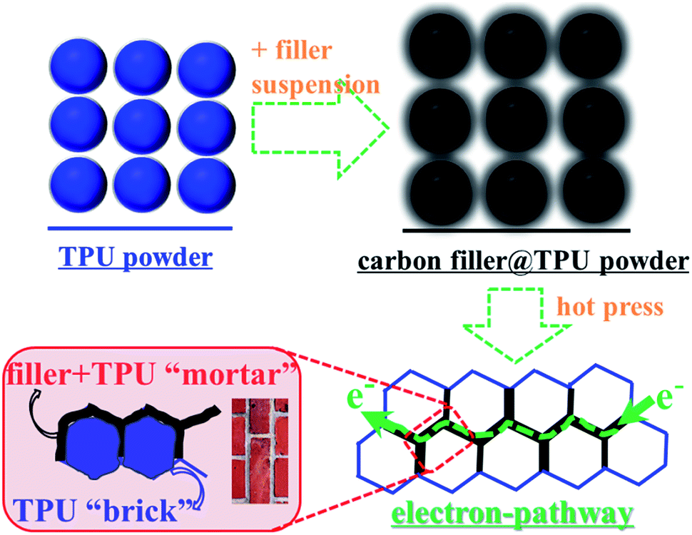 | ||
| Fig. 1 Schematic illustrations of the fabrication of TPU composites with carbon nanofillers and the “brick-wall” structure in TPU composites. | ||
3.2 Carbon nanofiller morphologies
Fig. 2 shows TEM images of raw carbon materials, CNTs, GNSs and CNSs, dispersed in DMF. CNTs have a rod-like structure (1D), and the TEM image reveals string-like single carbon nanotubes when dispersed in DMF under ultrasonication. GNSs exhibit a plate-like morphological structure (2D), containing 1–2 layers of wrinkled graphene, which is thin and transparent. CNSs display a branch-like morphology with obvious “arms” which tend to interconnect with each other to form a “cross-linked” structure (3D).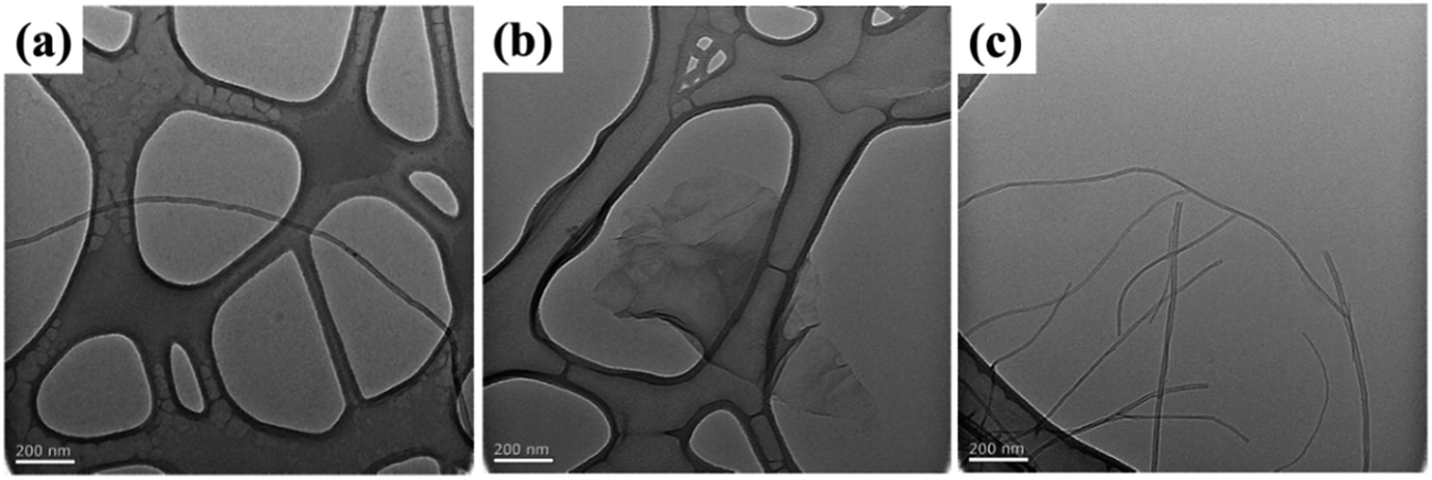 | ||
| Fig. 2 TEM images of (a) CNTs, (b) GNSs and (c) CNSs. | ||
3.3 Morphologies of carbon nanofillers at the elastomer interface
To observe the segregated network structure of all three carbon nanofillers, optical microscopy images are shown in Fig. 3. With increasing filler content, the segregated network becomes clearer and more interconnected, especially at high concentration. However, in comparison with GNSs and CNSs, the segregated network in the TPU/CNT system is less obvious, which is probably due to the relatively low filler dimensionality conducive to filler bundling/entanglement. Interestingly, at even 0.1 wt%, the segregated network for the TPU/CNS system is well marked, indicating the high efficiency in forming conductive pathways at the elastomer interface. | ||
| Fig. 3 Optical microscopy morphologies of CNTs, GNSs and CNSs at the TPU interface with filler contents of 0.1, 0.7 and 2 wt%, respectively. The scale bar is 100 μm. | ||
To further understand the differences in morphology of the three kinds of carbon nanofillers in the TPU matrix, SEM images of TPU composites with 0.7 wt% filler are shown in Fig. 4. Like in the optical microscopy images, the location of all carbon nanofillers at the elastomer interface is clearly observed. Besides, the corresponding magnified images on the right side indicate the penetration of TPU chains into the filler network. Dispersed single CNTs and bundles with a few nanotubes can be observed in the magnified SEM images on the right, while the GNSs display the typical morphology of wrinkled and stacked large graphene plates. In contrast, CNSs have a hair-like highly interconnected structure due to the branches or “arms” consistent with the TEM images in Fig. 2, and a tree root–soil structure is observed in the interfacial layer with TPU chains penetrated into the CNS network.
 | ||
| Fig. 4 SEM morphology of (a) CNTs, (b) GNSs and (c) CNSs at the TPU interface with a filler content of 0.7 wt%. | ||
3.4 Electrical conductivity
The volume electrical conductivity of TPU composites with the three types of carbon nanofillers is presented in Fig. 5. The CNTs and GNSs selected here are frequently used commercial carbon nanofillers for electrically conductive polymer composites. With the increasing filler content, the volume conductivity of TPU composites increases significantly after 0.3 wt% and it reaches a plateau once the filler content goes up to 1.2 wt%. However, the incorporation of only 0.1 wt% CNSs results in a dramatic improvement (5 orders of magnitude) of the volume conductivity for TPU composites, illustrating the much higher efficiency of CNSs for the formation of conductive paths at the TPU interface. Afterwards, the volume conductivity increases slowly (1–1.5 orders of magnitude) and it reaches almost a plateau at 0.7 wt% CNSs with much tapered increases at higher concentrations. Interestingly, at 0.3 wt% filler content, the TPU/CNS composite has a volume conductivity 4 orders of magnitude higher than that of the CNT and GNS composites. Modest conductivity increases for TPU composites with CNTs and GNSs at filler contents between 0.1 and 0.3 wt% are probably due to the filler stacking/agglomeration and/or inadequate connection at the elastomer interface (see Fig. 2 for the composites with 0.1% fillers). Moreover, the TPU/CNS system has higher electrical conductivity at all filler concentrations. The composite with 0.7 wt% CNSs has an electrical conductivity of 2.1 S m−1, which is even higher than that of 2 wt% CNTs (1.4 S m−1) and is similar to that of the TPU composite with 2 wt% GNSs (2.9 S m−1). | ||
| Fig. 5 Volume conductivity versus filler content for TPU composites. | ||
The classical percolation theory was used to calculate the percolation threshold for the different fillers:78,79
| σ ∝ σ0(Φ − ΦC)t | (1) |
As shown in the inset in Fig. 5, the percolation threshold of TPU composites with CNTs or GNSs is 0.088 and 0.1 wt%, respectively, while that for the TPU/CNS system is only 0.01 wt%. This super low ΦC for the TPU/CNS system is attributed to the filler interconnected morphology,70,80 favorable for the formation of conductive paths at the TPU interface. This value is currently the lowest reported in the literature for TPU composites with carbon nanofillers, indicative of the higher efficiency of the segregated filler network strategy used in this work compared to solution or melt mixing.26,39,74
Overall, the 3D CNSs show higher efficiency in forming conductive pathways at the elastomer interface in comparison with 2D GNSs and 1D CNTs, which is consistent with theoretical studies66 while different from other segregated network systems.49,67 This is likely due to the improved filler dispersion at the elastomer interface (see Fig. S2†) and the penetration of TPU chains into the CNS network (see Fig. 4).
3.5 Mechanical properties
The morphology of carbon nanofillers influences not only the electrical conductivities but also the mechanical properties of TPU composites (Fig. 6). As shown in Fig. 6(a), the TPU/CNT system exhibits the largest elongation at break with a value still around 1300% for the composite with 2 wt% CNTs. In contrast, the incorporation of GNSs gives rise to a marked decrease in the elongation at break (the 0.7 and 2 wt% GNS composites have elongations at break of 900% and 500%, respectively). This may be caused by the agglomeration of GNSs due to the stacking of graphene sheets, as shown in Fig. 4(b). The TPU/CNS composites also show lower elongation at break than the TPU/CNT system at all filler contents. The TPU/CNT system can effectively maintain a large elongation at break most likely due to the enhanced penetration of TPU chains into the looser CNT networks (see Fig. 3 and 4(a)) in comparison with the CNS and GNS systems. However, the elongations at break for TPU/CNS composites at very low filler loadings are still satisfactory (1500%, 1400% and 1100% at loadings of 0.1, 0.3 and 0.7 wt%, respectively), due to good filler dispersion at low loadings and the easy penetration of TPU chains into the CNS network. Such high elongations at break allow promising applications for stretchable conductive composites of these systems in view of their exceptional electrical conductivity. It is worth noting that these data are superior to those presented in Table 1 for the TPU composites fabricated by conventional methods. The relative Young's modulus data shown in Fig. 6(b) indicate that CNSs and GNSs have a comparable reinforcement effect, larger than that of the CNTs, most likely due to CNT bundling. | ||
| Fig. 6 (a) Elongation at break and (b) relative Young's modulus of TPU composites with different carbon nanofillers. | ||
3.6 Piezoresistive behaviors
To explore the strain sensing applications of these stretchable composites, the relative resistance change (ΔR/R0) plotted against strain is shown in Fig. 7. At 0.7 wt% filler content, the TPU/GNS system shows a much higher resistance change for 100–300% strain in comparison with the other composites due most likely to the sliding between graphene sheets during stretching.26,80 It evolves quickly to complete separation of the graphene–graphene contact (at 300% strain), and the resistance increases beyond the range of the multimeter (110 MΩ), and yet this strain is lower than the composite elongation at break (850%). This indicates that GNSs can potentially improve the strain sensitivity for TPU composites but not at high strains. Similar observations can be made for the 0.7 CNT, which can sustain relatively low tensile strains, e.g. 350%, but resistance data cannot be collected beyond that due to the multimeter resistance limit. However, the TPU/CNS system can sustain strains up to 1100% with large ΔR/R0 values at a high strain level, most suitable for stretchable strain sensor applications. The robust conductive networks of CNSs at 0.7 wt% filler content enable the TPU/CNS system to sustain high levels of tensile strain. By further increasing the filler content to 2 wt% (Fig. 7(b)), the TPU/GNS system still shows much higher ΔR/R0 at relatively low strain (100–300%) while the CNS system can sustain higher levels of strain (up to 650% when it breaks). Interestingly, at this filler content, the TPU/CNT system can be applied for a wider strain range (up to 950%), similar to the composite with only 0.7 wt% CNSs. Thus, carbon nanofiller dimensionality significantly affects the piezoresistive properties of the TPU composites. 2D GNSs shows high sensitivity at low strain levels due to easy sliding between the graphene sheets. 1D CNTs can sustain a high strain level even at high filler loading due to TPU chain penetration into a looser filler network.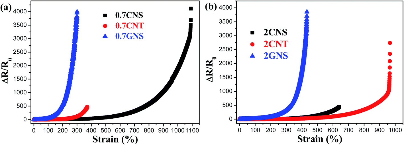 | ||
| Fig. 7 ΔR/R0 plotted against strain for TPU composites with (a) 0.7 and (b) 2 wt% carbon nanofillers. | ||
To further understand the effect of filler dimensionality on piezoresistive behavior, TPU composites with similar electrical conductivities but different contents of the three types of fillers are compared in Fig. 8(a and b). The 3D CNSs are superior to CNTs and GNSs for the fabrication of stretchable TPU composite strain sensors at low filler contents, while the TPU/GNS system has higher piezoresistive sensitivity at strains of less than 300%. To evaluate the strain sensitivity, gauge factors (GF) calculated from the ratio of ΔR/R0 and strain change, i.e. relating the slopes of ΔR/R0–strain curves obtained by a linear fitting with the corresponding strain change, are provided in Fig. 8(a and b). As shown in Fig. 8(a), the TPU composites with 0.1 wt% CNSs and 0.7 wt% CNTs have very similar slopes for strain within 150% and strain above 350%, indicating similar piezoresistive sensitivity. The gauge factor for TPU composites with both CNSs and CNTs within 150% strain is about 2.6, comparable with that reported for solution-mixed TPU/CNT composites.44 Besides, they have higher GF values (ca. 260) for strains above 350% by comparison with other literature reported stretchable strain sensors.81,82 However, the composite with 0.7 wt% GNSs has a larger GF (37) for low-level strain (<100%) and, interestingly, GF goes up to 3850 for strains between 250% and 300%, which is much higher than that of other TPU-based stretchable strain sensors reported in the literature.81 Although the TPU composite with 0.3 wt% CNSs has a lower GF at strains within 400%, it is able to sustain high-level strains and shows a GF of 2800 for strains of 850–1050%, much higher than that for other reported highly stretchable strain sensors.81,83 The stability of these composites was tested by cyclic testing as illustrated in Fig. 8(c–f). The cyclic testing results indicate that the TPU/CNS systems with 0.1 and 0.3 wt% filler show rather stable sensing behavior in spite of their relatively smaller ΔR/R0 amplitude in comparison with the 0.7 wt% CNTs and 0.7 wt% GNS composites. It is worth mentioning that, due to the competition between network de-construction and re-construction during the unloading and the creep characteristics of elastomer composites, the data show shoulder peaks, as also reported in other TPU composites.26,39,44,45,74,80 Interestingly, these shoulder peaks become weaker for the composites with more robust conductive networks, as revealed in Fig. 8(e and f), indicating that such networks exhibit better recovery upon unloading.80
 | ||
| Fig. 8 ΔR/R0–strain curves for the composites (a) 0.1 CNS and 0.7 CNT and (b) 0.3 CNS and 0.7 GNS, as well as the GF values for some strain regions. The inserts show their corresponding initial conductivities. Cyclic piezoresistive testing (under ca. 8.5 MPa) of TPU composites (c) 0.1 CNS, (d) 0.7 CNT, (e) 0.3 CNS and (f) 0.7 GNS, respectively. | ||
The effect of carbon nanofiller dimensionality on the properties of TPU composites can be summarized as follows: 3D CNSs provide very high electrical conductivity, relatively high elongation at break and good piezoresistive sensitivity; 2D GNSs enable high piezoresistive sensitivity, medium electrical conductivity, but severely reduced elongation at break; 1D CNTs provide the highest elongation at break but relatively low electrical conductivity. Consequently, judicious carbon nanofiller selection plays a crucial role in designing conductive elastomer composites for different applications.
3.7 Applications of stretchable conductive composites
 | ||
| Fig. 9 Strain sensor applications for joint motion detection: (a) knee bending and (b) wrist and (c) index finger bending. | ||
 | ||
| Fig. 10 ΔR/R0 plotted against strain for 0–100% strain and the LED bulb brightness change under 0 and 100% strain, respectively, for TPU composites with different carbon nanofillers. | ||
4. Conclusion
Electrically conductive thermoplastic elastomer composites with 1D CNTs, 2D GNSs and 3D CNSs were fabricated by building conductive pathways at the elastomer interface via a segregated network strategy. Comparing the three fillers, 3D CNSs have the lowest electrical percolation threshold (0.01 wt%) and show much higher electrical conductivity than CNTs or GNSs at the same filler loading, especially at low filler content. In terms of composite flexibility, the TPU/CNT and TPU/GNS systems have the highest and lowest elongation at break, respectively, due to different filler network morphologies as related to their different shape/dimensionality. The lower elongation at break in the TPU/GNS system translates into a higher piezoresistivity but a narrow sensing strain range. The TPU/CNS system shows a good combination of high electrical conductivity and high elongation at break. Good electrical conductivity and high elongation at break enable the potential application of these composites in stretchable strain sensors and conductors/resistors, as demonstrated by the examples given for human body motion detection and flexible wires. This study sheds light on the effect of filler shape/dimensionality on the electrical, mechanical and piezoresistive properties of TPU composites with a segregated network structure and opens the way for their use as single or hybrid fillers in different applications.Conflicts of interest
There are no conflicts to declare.Acknowledgements
We appreciate Parker Hannifin Corporation for the financial support of this work. We also thank Mr Dale Ashby and Mr Glenn Craig for useful discussion and suggestions. We greatly appreciate Applied Nanostructured Solutions LLC for providing CNSs for our research. The authors also thank Mrs Nanthawan Avishai and Dr Danqi Wang (both from the Swagelok Center for Surface Analysis of Materials of Case Western Reserve University) for SEM and TEM analysis.References
- S. P. Lacour, S. Wagner, Z. Huang and Z. Suo, Appl. Phys. Lett., 2003, 82, 2404–2406 CrossRef CAS.
- T. Sekitani, H. Nakajima, H. Maeda, T. Fukushima, T. Aida, K. Hata and T. Someya, Nat. Mater., 2009, 8, 494 CrossRef CAS PubMed.
- M. Park, J. Im, M. Shin, Y. Min, J. Park, H. Cho, S. Park, M.-B. Shim, S. Jeon and D.-Y. Chung, Nat. Nanotechnol., 2012, 7, 803 CrossRef CAS PubMed.
- S. Yao and Y. Zhu, Adv. Mater., 2015, 27, 1480–1511 CrossRef CAS PubMed.
- J. A. Rogers, T. Someya and Y. Huang, science, 2010, 327, 1603–1607 CrossRef CAS PubMed.
- U.-H. Shin, D.-W. Jeong, S.-M. Park, S.-H. Kim, H. W. Lee and J.-M. Kim, Carbon, 2014, 80, 396–404 CrossRef CAS.
- Z. Bao and X. Chen, Adv. Mater., 2016, 28, 4177–4179 CrossRef CAS PubMed.
- Y. Liu, K. He, G. Chen, W. R. Leow and X. Chen, Chem. Rev., 2017, 117, 12893–12941 CrossRef CAS PubMed.
- E. Roh, B.-U. Hwang, D. Kim, B.-Y. Kim and N.-E. Lee, ACS Nano, 2015, 9, 6252–6261 CrossRef CAS PubMed.
- M. Amjadi, A. Pichitpajongkit, S. Lee, S. Ryu and I. Park, ACS Nano, 2014, 8, 5154–5163 CrossRef CAS PubMed.
- T. Yamada, Y. Hayamizu, Y. Yamamoto, Y. Yomogida, A. Izadi-Najafabadi, D. N. Futaba and K. Hata, Nat. Nanotechnol., 2011, 6, 296 CrossRef CAS PubMed.
- J.-H. Pu, X.-J. Zha, M. Zhao, S. Li, R.-Y. Bao, Z.-Y. Liu, B.-H. Xie, M.-B. Yang, Z. Guo and W. Yang, Nanoscale, 2018, 10, 2191–2198 RSC.
- J. T. Muth, D. M. Vogt, R. L. Truby, Y. Mengüç, D. B. Kolesky, R. J. Wood and J. A. Lewis, Adv. Mater., 2014, 26, 6307–6312 CrossRef CAS PubMed.
- D. J. Lipomi, M. Vosgueritchian, B. C. Tee, S. L. Hellstrom, J. A. Lee, C. H. Fox and Z. Bao, Nat. Nanotechnol., 2011, 6, 788 CrossRef CAS PubMed.
- M. Amjadi, K. U. Kyung, I. Park and M. Sitti, Adv. Funct. Mater., 2016, 26, 1678–1698 CrossRef CAS.
- C. Yan, J. Wang, W. Kang, M. Cui, X. Wang, C. Y. Foo, K. J. Chee and P. S. Lee, Adv. Mater., 2014, 26, 2022–2027 CrossRef CAS PubMed.
- X. Li, T. Hua and B. Xu, Carbon, 2017, 118, 686–698 CrossRef CAS.
- Y. Wang, J. Hao, Z. Huang, G. Zheng, K. Dai, C. Liu and C. Shen, Carbon, 2018, 126, 360–371 CrossRef CAS.
- Y. Li, B. Zhou, G. Zheng, X. Liu, T. Li, C. Yan, C. Cheng, K. Dai, C. Liu and C. Shen, J. Mater. Chem. C, 2018, 6, 2258–2269 RSC.
- C. L. Choong, M. B. Shim, B. S. Lee, S. Jeon, D. S. Ko, T. H. Kang, J. Bae, S. H. Lee, K. E. Byun and J. Im, Adv. Mater., 2014, 26, 3451–3458 CrossRef CAS PubMed.
- M. Wang, K. Zhang, X.-X. Dai, Y. Li, J. Guo, H. Liu, G.-H. Li, Y.-J. Tan, J.-B. Zeng and Z. Guo, Nanoscale, 2017, 9, 11017–11026 RSC.
- H. Zhao and J. Bai, ACS Appl. Mater. Interfaces, 2015, 7, 9652–9659 CrossRef CAS PubMed.
- J. Wang, J. Jiu, M. Nogi, T. Sugahara, S. Nagao, H. Koga, P. He and K. Suganuma, Nanoscale, 2015, 7, 2926–2932 RSC.
- J. Park, Y. Lee, J. Hong, M. Ha, Y.-D. Jung, H. Lim, S. Y. Kim and H. Ko, ACS Nano, 2014, 8, 4689–4697 CrossRef CAS PubMed.
- W. Huang, K. Dai, Y. Zhai, H. Liu, P. Zhan, J. Gao, G. Zheng, C. Liu and C. Shen, ACS Appl. Mater. Interfaces, 2017, 9, 42266–42277 CrossRef CAS PubMed.
- H. Liu, J. Gao, W. Huang, K. Dai, G. Zheng, C. Liu, C. Shen, X. Yan, J. Guo and Z. Guo, Nanoscale, 2016, 8, 12977–12989 RSC.
- M. Knite, V. Teteris, A. Kiploka and J. Kaupuzs, Sens. Actuators, A, 2004, 110, 142–149 CrossRef CAS.
- M. Park, J. Park and U. Jeong, Nano Today, 2014, 9, 244–260 CrossRef CAS.
- L. Ma, W. Yang, Y. Wang, H. Chen, Y. Xing and J. Wang, Compos. Sci. Technol., 2018, 165, 190–197 CrossRef CAS.
- Y. Wei, S. Chen, Y. Lin, Z. Yang and L. Liu, J. Mater. Chem. C, 2015, 3, 9594–9602 RSC.
- S. Chen, Y. Wei, S. Wei, Y. Lin and L. Liu, ACS Appl. Mater. Interfaces, 2016, 8, 25563–25570 CrossRef CAS PubMed.
- J. R. Dunklin, G. T. Forcherio, K. R. Berry Jr and D. K. Roper, ACS Appl. Mater. Interfaces, 2013, 5, 8457–8466 CrossRef CAS PubMed.
- S. Zhao, J. Li, D. Cao, G. Zhang, J. Li, K. Li, Y. Yang, W. Wang, Y. Jin and R. Sun, ACS Appl. Mater. Interfaces, 2017, 9, 12147–12164 CrossRef CAS PubMed.
- K. Ke, V. S. Bonab, D. Yuan and I. Manas-Zloczower, Carbon, 2018, 139, 52–58 CrossRef CAS.
- T. S. Natarajan, S. B. Eshwaran, K. W. Stöckelhuber, S. Wießner, P. Pötschke, G. Heinrich and A. Das, ACS Appl. Mater. Interfaces, 2017, 9, 4860–4872 CrossRef CAS PubMed.
- L.-F. Ma, R.-Y. Bao, R. Dou, Z.-Y. Liu, W. Yang, B.-H. Xie, M.-B. Yang and Q. Fu, J. Mater. Chem. A, 2014, 2, 16989–16996 RSC.
- T. Li, J.-H. Pu, L.-F. Ma, R.-Y. Bao, G.-Q. Qi, W. Yang, B.-H. Xie and M.-B. Yang, Polym. Chem., 2015, 6, 7160–7170 RSC.
- T. Li, L.-F. Ma, R.-Y. Bao, G.-Q. Qi, W. Yang, B.-H. Xie and M.-B. Yang, J. Mater. Chem. A, 2015, 3, 5482–5490 RSC.
- Y. Zheng, Y. Li, K. Dai, M. Liu, K. Zhou, G. Zheng, C. Liu and C. Shen, Composites, Part A, 2017, 101, 41–49 CrossRef CAS.
- R. Zhang, H. Deng, R. Valenca, J. Jin, Q. Fu, E. Bilotti and T. Peijs, Compos. Sci. Technol., 2013, 74, 1–5 CrossRef CAS.
- M. Ji, H. Deng, D. Yan, X. Li, L. Duan and Q. Fu, Compos. Sci. Technol., 2014, 92, 16–26 CrossRef CAS.
- H. Deng, M. Ji, D. Yan, S. Fu, L. Duan, M. Zhang and Q. Fu, J. Mater. Chem. A, 2014, 2, 10048–10058 RSC.
- L. Lin, S. Liu, S. Fu, S. Zhang, H. Deng and Q. Fu, Small, 2013, 9, 3620–3629 CrossRef CAS PubMed.
- L. Lin, S. Liu, Q. Zhang, X. Li, M. Ji, H. Deng and Q. Fu, ACS Appl. Mater. Interfaces, 2013, 5, 5815–5824 CrossRef CAS PubMed.
- S. Xu, W. Yu, M. Jing, R. Huang, Q. Zhang and Q. Fu, J. Phys. Chem. C, 2017, 121, 2108–2117 CrossRef CAS.
- J. C. Grunlan, W. W. Gerberich and L. F. Francis, J. Appl. Polym. Sci., 2001, 80, 692–705 CrossRef.
- L. F. Francis, J. C. Grunlan, J. Sun and W. Gerberich, Colloids Surf., A, 2007, 311, 48–54 CrossRef CAS.
- X.-Y. Qi, D. Yan, Z. Jiang, Y.-K. Cao, Z.-Z. Yu, F. Yavari and N. Koratkar, ACS Appl. Mater. Interfaces, 2011, 3, 3130–3133 CrossRef CAS PubMed.
- J. Du, L. Zhao, Y. Zeng, L. Zhang, F. Li, P. Liu and C. Liu, Carbon, 2011, 49, 1094–1100 CrossRef CAS.
- J.-F. Gao, Z.-M. Li, Q.-j. Meng and Q. Yang, Mater. Lett., 2008, 62, 3530–3532 CrossRef CAS.
- H. Pang, L. Xu, D.-X. Yan and Z.-M. Li, Prog. Polym. Sci., 2014, 39, 1908–1933 CrossRef CAS.
- G. A. Gelves, M. H. Al-Saleh and U. Sundararaj, J. Mater. Chem., 2011, 21, 829–836 RSC.
- J. Chen, Y.-y. Shi, J.-h. Yang, N. Zhang, T. Huang, C. Chen, Y. Wang and Z.-w. Zhou, J. Mater. Chem., 2012, 22, 22398–22404 RSC.
- D. X. Yan, H. Pang, B. Li, R. Vajtai, L. Xu, P. G. Ren, J. H. Wang and Z. M. Li, Adv. Funct. Mater., 2015, 25, 559–566 CrossRef CAS.
- J. C. Grunlan, W. W. Gerberich and L. F. Francis, Polym. Eng. Sci., 2001, 41, 1947–1962 CrossRef CAS.
- H. Pang, D.-X. Yan, Y. Bao, J.-B. Chen, C. Chen and Z.-M. Li, J. Mater. Chem., 2012, 22, 23568–23575 RSC.
- C. Yu, Y. S. Kim, D. Kim and J. C. Grunlan, Nano Lett., 2008, 8, 4428–4432 CrossRef CAS PubMed.
- C. Yu, K. Choi, L. Yin and J. C. Grunlan, ACS Nano, 2011, 5, 7885–7892 CrossRef CAS PubMed.
- H. Pang, Y.-Y. Piao, Y.-Q. Tan, G.-Y. Jiang, J.-H. Wang and Z.-M. Li, Mater. Lett., 2013, 107, 150–153 CrossRef CAS.
- Y. A. Samad, Y. Li, A. Schiffer, S. M. Alhassan and K. Liao, Small, 2015, 11, 2380–2385 CrossRef PubMed.
- J. Li, S. Zhao, X. Zeng, W. Huang, Z. Gong, G. Zhang, R. Sun and C.-P. Wong, ACS Appl. Mater. Interfaces, 2016, 8, 18954–18961 CrossRef CAS PubMed.
- J. Kuang, L. Liu, Y. Gao, D. Zhou, Z. Chen, B. Han and Z. Zhang, Nanoscale, 2013, 5, 12171–12177 RSC.
- Y. Wu, Z. Wang, X. Liu, X. Shen, Q. Zheng, Q. Xue and J.-K. Kim, ACS Appl. Mater. Interfaces, 2017, 9, 9059–9069 CrossRef CAS PubMed.
- X. Liu, C. Tang, X. Du, S. Xiong, S. Xi, Y. Liu, X. Shen, Q. Zheng, Z. Wang and Y. Wu, Mater. Horiz., 2017, 4, 477–486 RSC.
- B. Krause, C. Barbier, K. Kunz and P. Pötschke, Polymer, 2018, 159, 75–85 CrossRef CAS.
- S. H. Xie, Y. Y. Liu and J. Y. Li, Appl. Phys. Lett., 2008, 92, 243121 CrossRef.
- P. G. Ren, Y. Y. Di, Q. Zhang, L. Li, H. Pang and Z. M. Li, Macromol. Mater. Eng., 2012, 297, 437–443 CrossRef CAS.
- J. F. Christ, N. Aliheidari, A. Ameli and P. Pötschke, Mater. Des., 2017, 131, 394–401 CrossRef CAS.
- H. Liu, Q. Li, S. Zhang, R. Yin, X. Liu, Y. He, K. Dai, C. Shan, J. Guo and C. Liu, J. Mater. Chem. C, 2018, 6, 12121–12141 RSC.
- Z. Sang, K. Ke and I. Manas-Zloczower, ACS Appl. Mater. Interfaces, 2018, 10(42), 36483–36492 CrossRef CAS PubMed.
- Z. Sang, K. Ke and I. Manas-Zloczower, ACS Appl. Polym. Mater., 2019, 1(4), 714–721 CrossRef CAS.
- R. Nadiv, G. Shachar, S. Peretz-Damari, M. Varenik, I. Levy, M. Buzaglo, E. Ruse and O. Regev, Carbon, 2018, 126, 410–418 CrossRef CAS.
- H. Kim, Y. Miura and C. W. Macosko, Chem. Mater., 2010, 22, 3441–3450 CrossRef CAS.
- H. Liu, Y. Li, K. Dai, G. Zheng, C. Liu, C. Shen, X. Yan, J. Guo and Z. Guo, J. Mater. Chem. C, 2016, 4, 157–166 RSC.
- J. Chen, Z.-x. Zhang, W.-b. Huang, J.-h. Yang, Y. Wang, Z.-w. Zhou and J.-h. Zhang, Mater. Des., 2015, 69, 105–113 CrossRef CAS.
- P. Costa, C. Silvia, J. Viana and S. L. Mendez, Composites, Part B, 2014, 57, 242–249 CrossRef CAS.
- M. Liu, C. Zhang, W. W. Tjiu, Z. Yang, W. Wang and T. Liu, Polymer, 2013, 54, 3124–3130 CrossRef CAS.
- L.-F. Ma, R.-Y. Bao, R. Dou, S.-D. Zheng, Z.-Y. Liu, R.-Y. Zhang, M.-B. Yang and W. Yang, Compos. Sci. Technol., 2016, 128, 176–184 CrossRef CAS.
- B. e. Kilbride, J. Coleman, J. Fraysse, P. Fournet, M. Cadek, A. Drury, S. Hutzler, S. Roth and W. Blau, J. Appl. Phys., 2002, 92, 4024–4030 CrossRef CAS.
- S. L. Yu, X. P. Wang, H. X. Xiang, L. P. Zhu, M. Tebyetekerwa and M.F. Zhu, Carbon, 2018, 140, 1–9 CrossRef CAS.
- Q. Fan, Z. Qin, S. Gao, Y. Wu, J. Pionteck, E. Mäder and M. Zhu, Carbon, 2012, 50, 4085–4092 CrossRef CAS.
- P. Slobodian, P. Riha and P. Sáha, Carbon, 2012, 50, 3446–3453 CrossRef CAS.
- G. Cai, J. Wang, K. Qian, J. Chen, S. Li and P. S. Lee, Adv. Sci., 2016, 4, 1600190–1600196 CrossRef PubMed.
Footnote |
| † Electronic supplementary information (ESI) available. See DOI: 10.1039/c9na00176j |
| This journal is © The Royal Society of Chemistry 2019 |